EP0429523B1 - Tube endotracheal - Google Patents
Tube endotracheal Download PDFInfo
- Publication number
- EP0429523B1 EP0429523B1 EP89909721A EP89909721A EP0429523B1 EP 0429523 B1 EP0429523 B1 EP 0429523B1 EP 89909721 A EP89909721 A EP 89909721A EP 89909721 A EP89909721 A EP 89909721A EP 0429523 B1 EP0429523 B1 EP 0429523B1
- Authority
- EP
- European Patent Office
- Prior art keywords
- tube
- pull
- distal end
- tip
- cuff
- Prior art date
- Legal status (The legal status is an assumption and is not a legal conclusion. Google has not performed a legal analysis and makes no representation as to the accuracy of the status listed.)
- Expired
Links
- 238000002627 tracheal intubation Methods 0.000 claims abstract description 30
- 230000008878 coupling Effects 0.000 claims abstract description 10
- 238000010168 coupling process Methods 0.000 claims abstract description 10
- 238000005859 coupling reaction Methods 0.000 claims abstract description 10
- 239000012528 membrane Substances 0.000 claims abstract description 9
- 230000004913 activation Effects 0.000 claims abstract description 3
- 239000000463 material Substances 0.000 claims description 5
- 210000004704 glottis Anatomy 0.000 abstract description 8
- 210000003437 trachea Anatomy 0.000 abstract description 3
- 238000003780 insertion Methods 0.000 description 6
- 230000037431 insertion Effects 0.000 description 6
- 210000004379 membrane Anatomy 0.000 description 6
- 210000003800 pharynx Anatomy 0.000 description 6
- 210000000492 nasalseptum Anatomy 0.000 description 5
- 208000037656 Respiratory Sounds Diseases 0.000 description 4
- 238000013461 design Methods 0.000 description 4
- 210000003128 head Anatomy 0.000 description 4
- 238000000034 method Methods 0.000 description 4
- 230000029058 respiratory gaseous exchange Effects 0.000 description 4
- 230000008901 benefit Effects 0.000 description 3
- 230000008859 change Effects 0.000 description 3
- 230000000694 effects Effects 0.000 description 3
- 238000004519 manufacturing process Methods 0.000 description 3
- 210000004400 mucous membrane Anatomy 0.000 description 3
- 210000001989 nasopharynx Anatomy 0.000 description 3
- 210000001331 nose Anatomy 0.000 description 3
- 230000002269 spontaneous effect Effects 0.000 description 3
- 230000003187 abdominal effect Effects 0.000 description 2
- 230000003444 anaesthetic effect Effects 0.000 description 2
- 210000003811 finger Anatomy 0.000 description 2
- 230000000977 initiatory effect Effects 0.000 description 2
- 239000002184 metal Substances 0.000 description 2
- 238000002360 preparation method Methods 0.000 description 2
- 230000000284 resting effect Effects 0.000 description 2
- 238000000926 separation method Methods 0.000 description 2
- 239000007787 solid Substances 0.000 description 2
- 230000003144 traumatizing effect Effects 0.000 description 2
- GXFZCDMWGMFGFL-KKXMJGKMSA-N (+)-Tubocurarine chloride hydrochloride Chemical compound [Cl-].[Cl-].C([C@H]1[N+](C)(C)CCC=2C=C(C(=C(OC3=CC=C(C=C3)C[C@H]3C=4C=C(C(=CC=4CC[NH+]3C)OC)O3)C=21)O)OC)C1=CC=C(O)C3=C1 GXFZCDMWGMFGFL-KKXMJGKMSA-N 0.000 description 1
- 206010002091 Anaesthesia Diseases 0.000 description 1
- 241001111317 Chondrodendron tomentosum Species 0.000 description 1
- 206010011224 Cough Diseases 0.000 description 1
- 239000008709 Curare Substances 0.000 description 1
- 208000027418 Wounds and injury Diseases 0.000 description 1
- 230000003213 activating effect Effects 0.000 description 1
- 230000004075 alteration Effects 0.000 description 1
- 238000001949 anaesthesia Methods 0.000 description 1
- 230000037005 anaesthesia Effects 0.000 description 1
- HNYOPLTXPVRDBG-UHFFFAOYSA-N barbituric acid Chemical compound O=C1CC(=O)NC(=O)N1 HNYOPLTXPVRDBG-UHFFFAOYSA-N 0.000 description 1
- 238000005452 bending Methods 0.000 description 1
- 238000004891 communication Methods 0.000 description 1
- 230000006378 damage Effects 0.000 description 1
- 239000013536 elastomeric material Substances 0.000 description 1
- 210000004247 hand Anatomy 0.000 description 1
- 210000003026 hypopharynx Anatomy 0.000 description 1
- 230000001939 inductive effect Effects 0.000 description 1
- 238000002347 injection Methods 0.000 description 1
- 239000007924 injection Substances 0.000 description 1
- 208000014674 injury Diseases 0.000 description 1
- 238000010253 intravenous injection Methods 0.000 description 1
- 230000003387 muscular Effects 0.000 description 1
- 230000000149 penetrating effect Effects 0.000 description 1
- 230000011514 reflex Effects 0.000 description 1
- 230000000241 respiratory effect Effects 0.000 description 1
- 230000004044 response Effects 0.000 description 1
- 210000001584 soft palate Anatomy 0.000 description 1
- 239000000243 solution Substances 0.000 description 1
- 210000003813 thumb Anatomy 0.000 description 1
- 238000013022 venting Methods 0.000 description 1
Images

Classifications
-
- A—HUMAN NECESSITIES
- A61—MEDICAL OR VETERINARY SCIENCE; HYGIENE
- A61M—DEVICES FOR INTRODUCING MEDIA INTO, OR ONTO, THE BODY; DEVICES FOR TRANSDUCING BODY MEDIA OR FOR TAKING MEDIA FROM THE BODY; DEVICES FOR PRODUCING OR ENDING SLEEP OR STUPOR
- A61M16/00—Devices for influencing the respiratory system of patients by gas treatment, e.g. ventilators; Tracheal tubes
- A61M16/04—Tracheal tubes
-
- A—HUMAN NECESSITIES
- A61—MEDICAL OR VETERINARY SCIENCE; HYGIENE
- A61M—DEVICES FOR INTRODUCING MEDIA INTO, OR ONTO, THE BODY; DEVICES FOR TRANSDUCING BODY MEDIA OR FOR TAKING MEDIA FROM THE BODY; DEVICES FOR PRODUCING OR ENDING SLEEP OR STUPOR
- A61M16/00—Devices for influencing the respiratory system of patients by gas treatment, e.g. ventilators; Tracheal tubes
- A61M16/04—Tracheal tubes
- A61M16/0402—Special features for tracheal tubes not otherwise provided for
- A61M16/0418—Special features for tracheal tubes not otherwise provided for with integrated means for changing the degree of curvature, e.g. for easy intubation
-
- A—HUMAN NECESSITIES
- A61—MEDICAL OR VETERINARY SCIENCE; HYGIENE
- A61M—DEVICES FOR INTRODUCING MEDIA INTO, OR ONTO, THE BODY; DEVICES FOR TRANSDUCING BODY MEDIA OR FOR TAKING MEDIA FROM THE BODY; DEVICES FOR PRODUCING OR ENDING SLEEP OR STUPOR
- A61M16/00—Devices for influencing the respiratory system of patients by gas treatment, e.g. ventilators; Tracheal tubes
- A61M16/04—Tracheal tubes
- A61M16/0434—Cuffs
Definitions
- the invention relates to an endotracheal tube for blind, nasal intubation, and of the type in which the tube comprises a distal end, a proximal end, an inflatable cuff positioned at a relatively short distance from the distal end, said cuff having an associated channel extending longitudinally in the wall tube and intended to connect the interior of the cuff with an air supply hose provided with valve, means for altering the curvature of the tube during intubation
- aditus laryngis necessitates general anaesthesia and total muscular relaxation by injection of a curare preparation, frequent venting on mask and putting on a mouth piece in upper jaw.
- the exposure of aditus laryngis by means of a laryngoscope may require, particularly in adult male patients, quite strong arms, a requirement which nurse anaesthetists or female anaesthesiologists are not always able to fulfil, and the intubation procedure is therefore often time-consuming and time-wasting.
- the starting point of the invention is the anatomically close relation between aditus oesophagus and aditus trachea along with the fact that respiration continues spontaneously after the patient has been fully anaesthetized by an intravenous injection of a quickly acting preparation of barbituric acid.
- a stethoscope connected with the tube it will thus be possible to locate the position of the tip of a tube inserted in respiratory and oesophageal passages.
- the tube tip Upon cessation of the spontaneous respiration the tube tip has engaged the oesophagus orifice and upon resumption of respiration the tube tip is located on a level with aditus laryngis.
- a drawback of the prior art disclosed in said US patent No. 4 150 676 is that the "blind", i.e. the non-laryngoscopic intubation implies some sort of remote control of the tube tip in the form of a forward tilting in order to engage aditus laryngis when inserting the tube, and that the tensioning on the ring provokes the curvature of the tube to change, i.e. increased curvature throughout the length of the tube.
- Such an alteration of the curvature of the tube which, as said, applies to the entire length of the tube means that blind intubation effected in this manner only succeeds after repeated attempts with varying bending of the patient's head and varying curvature of the tube.
- the invention aims at eliminating said drawbacks and contemplates the provision of a tube structure allowing a considerably easier intubation which is, moreover, more gentle to the patient.
- an endotracheal tube of the above mentioned type is according to the invention characterized in that the tube between the distal end and the cuff presents a smaller flexural rigidity than the remainder of the tube.
- Such an endotracheal tube offers the following advantages.
- said smaller flexural rigidity may be obtained in that at least one, mainly V-shaped incision is provided in the tube wall, that a flexible bellows-shaped membrane is provided for air-, gas- and liquidtight closing of the incision, and that a point of the tube wall between the distal end and the nearest side of the V-incision is connected with a pull-wire inserted into a longitudinal channel in the tube wall, said pull-wire being connected with a ring positioned outside the tube.
- the operator chooses the most spacious side allowing the tube to be inserted with its cylindrical side against nasal septum so that the bevelled end of the tube, the patient's head being placed in normal-anatomic position (the nose turning right up and the neck resting directly on the bed without any intermediate layer), after passage through choana (posterior nares) points towards the plane of glottis.
- the tube be provided with two mainly V-shaped, preferably symmetrically opposed incisions in two opposite sides of the tube and in relation to a plane (saggital plane; containing the longitudinal axis of the tube, said two incisions being preferably equally spaced from the distal end, either incision being closed by an associated, bellows-shaped membrane, and in that there are provided two associated pull-wires inserted in their respective, longitudinal channel of the tube wall, with pertaining rings.
- Another solution aims at making the tube tip manually pivotal about a luminal axis in conformity with the actual anatomic configuration.
- the connection between the tube tip and the tube is inseparable with a rotational angle of 180° and includes locking means ensuring that the bevelled edge of the tube tip in both positions is on the plane of glottis.
- Both designs allow for inserting the tube tip with its cylindrical wall facing nasal septum and later on, during the intubation course, for graduating the curvature of the tube tip via pull means.
- the end piece At the initiation of tensioning, the end piece is at first made to tilt more or less in relation to the tube because of the difference in flexural rigidity. If after the maximum deflection of the end piece a pulling force is still exerted on the pull means, the the tube proper is bent to increase its curvature.
- the tube according to the invention provides for obtaining a selective, graduated change of curvature of the distal end (tube tip) based on the auscultorically determined position thereof in upper tracheal passage and in relation to aditus oesophagus.
- the intubation of trachea is normally effected by exposure of aditus laryngis when the patient is in supine position but in case of heavily injured patients, the nasal intubation with the tube according to the invention may be applied as well in the side position, the so-called NATO-position, and in abdominal position, inter alia because the operator after having preliminarily adjusted the position of the end piece only needs one hand for the insertion of the tube by suitable two-phased change of the curvature of the tube tip while the free hand simultaneously adjusts and supports the patient's head.
- the opening angle of the V-shaped incision(s) may for instance amount to 60° so that the pivot angle of the end piece in the initiating phase of intubation may amount to about 60° to either side in the saggital plane (corresponding to the drawing plane) about an axis perpendicular thereto in coincidence with the peak of the V-shaped incision which acts as a hinge for the tilting of the end piece.
- This zone, at the peak of the V-shaped incision, of the tube wall acts as a hinge for the tilting of the end piece.
- the bellows membrane ensures the necessary, tight separation between the interior of the tube and the environments in nasal fossae, pharynx and aditus laryngis of the patient.
- Fig. 1 illustrates an example of designing an endotracheal tube according to the invention.
- nasal intubation is effected, but oral intubation may be effected as well, mainly in the same manner.
- the tube generally designated 1 is made from resilient plastic material and is slightly curved as shown in Fig. 1 (in the drawing plane of Fig. 1). In view of the fact that this tube is comparatively long (e.g. about 30 cm) compared to the diameter (e.g. about 1.5 cm) the tube is for the sake of clearness cut off at A in Fig. 1, but it is obvious that the two parts of the tube actually are integral.
- Reference numeral 2 shows the distal end of tube 1 which by a doctor, a surgeon or an anaesthesiologist, hereinafter named operator, is to be inserted in nasal fossae of a patient and onwards to hypopharynx.
- An extension 4 is coupled to the proximal end 3 of tube 1 and is operated by the operator during intubation. As it will be explained later on, extension 4 may be disconnected tube 1, the joint between said two members being shown by reference numeral 5.
- the external surface of tube 1 is provided with a centimetre-indication (not shown) used by the operator during intubation.
- Tube 1 is at distal end 2 provided with an end piece 6 which is connected by a coupling 7 pivotal about its longitudinal axis 0 with tube 1 proper.
- the lumen 8 in tube 1 extends all the way from proximal end 3 to distal end 2 where it discharges into the opening 6a in end piece 6.
- 1a designates the internal surface of tube 1.
- a mainly V-shaped incision 10 from the convex side of the tube to a point V at the internal surface la of the tube at the concave side of the tube is provided in tube 1 in the vicinity of coupling 7.
- a bellows-shaped membrane of plastic or elastomeric material is shown by 11.
- tube 1 is provided with an inflatable sleeve 12, a so-called cuff.
- a solid collar 13 (see also Fig. 4) by which the operator with his thumb and index finger can hold tube 1.
- 14 designates a fitting or connector for connection with a thin tube with valve means for the supply of air to cuff 12 through a longitudinal channel 15 (illustrated in double dot-and-dash line) extending in the tube wall and along the convex side of the tube from connector 14 to the interior of cuff 12.
- 16 is a connector to be connected with a stethoscope, not shown.
- 17 is an ring to be activated by the operator's index finger.
- Said ring 17 is connected with a pull-wire 18 of metal which as illustrated in a dotted line in Fig. 1 is passed through a channel extending along the concave side of the tube and onwards to a point B of the tube wall on the side facing distal end 2 in relation to V-incision 10.
- Pull-wire 18 leaves its longitudinal channel at a point 19 at a suitable distance from collar 13.
- FIG. 1 illustrates (in dotted line) the position of end piece 6 when the operator by tensioning the ring 17 and thus also pull-wire 18 has made the end piece to tilt an angle substantially equal to the opening angle of V-incision 10, while bellows membrane 11 is collapsing.
- end piece 6 is by means of coupling 7 pivotal about its axis corresponding to the longitudinal axis of the tube.
- Fig. 2 illustrates the proximal end of the tube with end piece 6 turned 90° in relation to the plane in Fig. 1 and, as it will appear from Figs 2 and 3, end piece 6 is bevelled in relation to axis 0.
- Fig. 3 illustrates on a larger scale and axially the proximal end of the tube.
- Fig. 3 is a design example of how to obtain such a pivotability.
- end piece 6 is provided with a radially inwards extending collar 20 for insertion into a corresponding groove 21 at the end of tube 1 so that end piece 6 in the axial direction is kept firmly to the tube - which is of utmost importance with respect to safety, since end piece 6 during intubation must never be released from tube 1 - but, nevertheless, so that it may be pivoted about its longitudinal axis 0.
- Two small locking projections 22, 23, serve by engagement with corresponding depressions to lock end piece 6 with tube 1 in determined, 180° separate angle positions.
- end piece 6 is connected directly with tube 1, but in view of the fact that the tube is flexible per se and has a wall of relatively small wall thickness it may be advantageous to connect end piece 6 with an intermediate piece, not shown in the drawings, which is in firm and permanent communication with tube 1 proper and may be made from a suitable plastic material of sufficient thickness for obtaining a satisfactory design of the individual locking parts of the coupling.
- a rhinoscopic estimate of the nasal fossae lumen may for instance be effected prior to intubation.
- the tube tip i.e. end piece 6 may be pivoted manually in relation to tube 1 so as to be inserted into the most spacious half of nasal fossae with its cylindrical side facing nasal septum and thus with the bevelled side facing the wing of the nose.
- Tube 1 with end piece 6 pre-adjusted in angle position is rubbed into an anaesthetic creme and is inserted while in connection with extension 4 and the stetoscope, until being resisted by the rear wall of nasopharynx.
- Tube 1 is pulled a little back and upon tensioning pull-wire 18 by means of ring 17 the tube tip is made to pivot towards the axis of pharynx between the rear wall and soft palate of nasopharynx, thereby preventing injury to the mucous membrane of the rear wall at the risk that the end edge of end piece 6 penetrates under the mucous membrane.
- Tube 1 is now pulled slowly back until the respiratory sound occurs again as a sign that the tube tip is now located opposite the lowermost limit of aditus laryngis. Simultaneously with pulling back, a slight intensifying activation of the wire drive is effected. When the slight resistance ceases tube tip is positioned at aditus laryngis and the tube may now under stetoscopic control of continued respiration be further inserted by slackening the pull on ring 17.
- a reflex cough is elicited and the tube is further inserted some centimetre (read on the external side of tube 1 in relation to nostril), following which a suitable filling of cuff 12 is effected by supplying air through connector 14 and the associated channel 15.
- a suitable filling of cuff 12 is effected by supplying air through connector 14 and the associated channel 15.
- the correct placing under glottis is ascertained by resistance against attempts of pulling back.
- Extension 4 is then removed and proximal end 3 of tube 1 is connected with the anaesthetic source.
- Fig. 4 is an example of designing extension 4 made from solid plastic material and provided with a fixed collar 13, connector hose 16 to be connected with a stethoscope and with stepped profiled cone 30 with a view to be connected with tubes of different lumen 30 at the proximal end of tube, cf. Fig. 1.
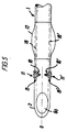
- Fig. 5 illustrates a second embodiment of the part of the tube shown to the left in Fig. 1 (to the left of cut A in the drawing of Fig. 1).
- Fig. 5 shows again the distal end 2 of tube 1, orifice 6a provided therein in an oblique plane in relation to the drawing plane of Fig. 5, and cuff 12.
- tube 1 now extends straight, i.e. without the curvature traditional of intubation tubes and, moreover, distal end 2 of the tube, contrary to the embodiment according to Fig. 1, is designed without end piece 6 and associated coupling 7.
- tube 1 now includes between distal end 2 and cuff 12 two, substantially V-shaped incisions 10, 10′ preferably provided in two opposite sides of the tube, symmetrically opposed and in relation to the saggital plane (plane including the longitudinal axis 0 of the tube and in the plane of Fig. 5).
- Said two V-shaped incisions - each with an opening angle likewise preferably of 60° - are also closed by respective bellows-shaped membranes 11, 11′ and are preferably positioned at equal distance from the distal end of the tube.
- the embodiment according to Fig. 5 offers the advantage already mentioned that it is possible with the same tube to effect right-sided or left-sided intubation and it entails, moreover, the advantage that there is no need of designing the tube with pivotal end piece (simpler manufacturing, safety against accidental separation of end piece from the tube) and that the resiliency of the material (plastic) of the tube wall between the peaks of the two V-incisions causes the tube during insertion into nasopharynx with patient's head in normal-anatomic position, to bear automatically against the rearmost pharynx wall, thereby for certain engaging the entry of oesophagus with cessation of the ausculatorily ascertained spontaneous respiratory sound that is the important reference of the two-phased intubation course.
- the extension may be provided with some sort of pistol butt having a slide device and ring for activating the metallic wire.
Landscapes
- Health & Medical Sciences (AREA)
- Pulmonology (AREA)
- Heart & Thoracic Surgery (AREA)
- Engineering & Computer Science (AREA)
- Anesthesiology (AREA)
- Biomedical Technology (AREA)
- Emergency Medicine (AREA)
- Hematology (AREA)
- Life Sciences & Earth Sciences (AREA)
- Animal Behavior & Ethology (AREA)
- General Health & Medical Sciences (AREA)
- Public Health (AREA)
- Veterinary Medicine (AREA)
- Surgical Instruments (AREA)
- External Artificial Organs (AREA)
Abstract
Claims (6)
Priority Applications (1)
| Application Number | Priority Date | Filing Date | Title |
|---|---|---|---|
| AT89909721T ATE79286T1 (de) | 1988-08-22 | 1989-08-15 | Luftroehrenrohr. |
Applications Claiming Priority (4)
| Application Number | Priority Date | Filing Date | Title |
|---|---|---|---|
| DK4700/88 | 1988-08-22 | ||
| DK470088A DK470088D0 (da) | 1988-08-22 | 1988-08-22 | Endotracheal tube til blind, nasal intubation under auskultatorisk-taktil kontrol |
| DK103189A DK165771C (da) | 1988-08-22 | 1989-03-03 | Endotracheal tube |
| DK1031/89 | 1989-03-03 |
Publications (2)
| Publication Number | Publication Date |
|---|---|
| EP0429523A1 EP0429523A1 (fr) | 1991-06-05 |
| EP0429523B1 true EP0429523B1 (fr) | 1992-08-12 |
Family
ID=26065103
Family Applications (1)
| Application Number | Title | Priority Date | Filing Date |
|---|---|---|---|
| EP89909721A Expired EP0429523B1 (fr) | 1988-08-22 | 1989-08-15 | Tube endotracheal |
Country Status (3)
| Country | Link |
|---|---|
| EP (1) | EP0429523B1 (fr) |
| DK (1) | DK165771C (fr) |
| WO (1) | WO1990001964A1 (fr) |
Cited By (2)
| Publication number | Priority date | Publication date | Assignee | Title |
|---|---|---|---|---|
| US7654264B2 (en) | 2006-07-18 | 2010-02-02 | Nellcor Puritan Bennett Llc | Medical tube including an inflatable cuff having a notched collar |
| CN104707231A (zh) * | 2015-03-04 | 2015-06-17 | 衡垒 | 可调节方向的经鼻插管用自带光源引导管 |
Families Citing this family (11)
| Publication number | Priority date | Publication date | Assignee | Title |
|---|---|---|---|---|
| IS7278A (is) * | 2001-11-26 | 2003-05-27 | Merlyn Associates, Inc. | Barkaslanga með stefnustjórnanlegum enda og stöðuhaldandi búnaði |
| GB2471390B8 (en) * | 2009-06-24 | 2012-09-12 | Oron Zachar | Breathing intubation method, apparatus and kit |
| GB2472403A (en) * | 2009-08-04 | 2011-02-09 | Michael Mccooe | Endotracheal tube with hinged portion |
| KR101274271B1 (ko) | 2011-04-28 | 2013-06-14 | 연세대학교 원주산학협력단 | 굴곡도의 조절이 가능한 기관튜브 |
| CN103656821B (zh) * | 2013-12-17 | 2015-10-21 | 鲍永新 | 尖端可控型气管导管 |
| CN104116486B (zh) * | 2014-08-11 | 2016-10-19 | 蔡明秀 | 一种灯光喉镜导芯 |
| WO2017123941A1 (fr) * | 2016-01-15 | 2017-07-20 | Farbes Medical, Llc | Tubes endotrachéaux articulables dans deux directions, compétents en imagerie |
| GB2563567B (en) | 2017-05-05 | 2022-01-05 | Flexicare Group Ltd | Intubation devices |
| CN111658938B (zh) * | 2020-04-30 | 2022-11-18 | 南通市第一人民医院 | 一种手动调整副通气管弯曲方向的双腔支气管导管 |
| IT202100001085A1 (it) * | 2021-01-22 | 2022-07-22 | Medsniper S R L | Tubo endotracheale |
| CN120586231B (zh) * | 2025-08-07 | 2025-10-03 | 上海埃立孚医疗科技有限公司 | 一种可调可视可插管的口咽通气异型导管座 |
Family Cites Families (4)
| Publication number | Priority date | Publication date | Assignee | Title |
|---|---|---|---|---|
| US4150676A (en) * | 1975-07-01 | 1979-04-24 | National Catheter Corp. | Endotracheal tubes with intubation direction control means |
| US4329983A (en) * | 1980-05-09 | 1982-05-18 | Fletcher Thomas S | Guide device for endotracheal tubes |
| US4622965A (en) * | 1984-08-30 | 1986-11-18 | Edward Teeple | Endotracheal tube |
| US4589410A (en) * | 1985-07-15 | 1986-05-20 | Miller Larry S | Endotracheal tube |
-
1989
- 1989-03-03 DK DK103189A patent/DK165771C/da not_active IP Right Cessation
- 1989-08-15 EP EP89909721A patent/EP0429523B1/fr not_active Expired
- 1989-08-15 WO PCT/DK1989/000195 patent/WO1990001964A1/fr not_active Ceased
Cited By (3)
| Publication number | Priority date | Publication date | Assignee | Title |
|---|---|---|---|---|
| US7654264B2 (en) | 2006-07-18 | 2010-02-02 | Nellcor Puritan Bennett Llc | Medical tube including an inflatable cuff having a notched collar |
| US8096299B2 (en) | 2006-07-18 | 2012-01-17 | Nellcor Puritan Bennett Llc | Medical tube including an inflatable cuff having a notched collar |
| CN104707231A (zh) * | 2015-03-04 | 2015-06-17 | 衡垒 | 可调节方向的经鼻插管用自带光源引导管 |
Also Published As
| Publication number | Publication date |
|---|---|
| DK165771B (da) | 1993-01-18 |
| EP0429523A1 (fr) | 1991-06-05 |
| DK165771C (da) | 1993-06-14 |
| DK103189D0 (da) | 1989-03-03 |
| WO1990001964A1 (fr) | 1990-03-08 |
| DK103189A (da) | 1990-02-23 |
Similar Documents
| Publication | Publication Date | Title |
|---|---|---|
| US4848331A (en) | Apparatus and method for pulmonary ventilation of a patient concurrent with fiberoptic respiratory tract examination and tracheal intubation | |
| US5941816A (en) | Viewing system with adapter handle for medical breathing tubes | |
| US4329983A (en) | Guide device for endotracheal tubes | |
| US6050264A (en) | Laryngeal mask assemblies | |
| US5694929A (en) | Method and apparatus for ventilation/oxygenation during guided insertion of an endotracheal tube | |
| US5203320A (en) | Tracheal intubation guide | |
| RU2336909C2 (ru) | Дыхательное устройство ларингеальной маски | |
| US4338930A (en) | Airway intubator | |
| US5174283A (en) | Blind orolaryngeal and oroesophageal guiding and aiming device | |
| CA2067782C (fr) | Dispositif orolarynge et oropharynge de guidage et de ciblage a l'aveugle | |
| EP2326377B1 (fr) | Dilatateur tronconique de trachéostomie aisé à tenir | |
| JPH05212120A (ja) | 医療−外科用装置 | |
| GB2317342A (en) | Laryngeal mask assembly | |
| EP0596517A1 (fr) | Appareil de secours de réanimation | |
| US20100030057A1 (en) | Imaging catheter | |
| US20030062039A1 (en) | Intubation system | |
| WO2012100016A1 (fr) | Appareil, systèmes, et procédés d'accès aux voies aériennes avec des instruments médicaux sans interruption de l'assistance respiratoire | |
| WO1997026036A1 (fr) | Dispositif pour intubation endotracheale | |
| WO1990001964A1 (fr) | Tube endotracheal | |
| JP2011525830A (ja) | 拡張器ローディングカテーテル | |
| EP4181994B1 (fr) | Kit de composants pour trachéotomie percutanée par dilatation extrusive | |
| US8307824B2 (en) | Method of performing a tracheostomy | |
| EP2281594B1 (fr) | Ensemble de dilatateur et dispositif pour faciliter la trachéostomie | |
| KR20190088668A (ko) | 기도삽관 튜브 | |
| CN102018549A (zh) | 一种经皮气管切开器 |
Legal Events
| Date | Code | Title | Description |
|---|---|---|---|
| PUAI | Public reference made under article 153(3) epc to a published international application that has entered the european phase |
Free format text: ORIGINAL CODE: 0009012 |
|
| 17P | Request for examination filed |
Effective date: 19910218 |
|
| AK | Designated contracting states |
Kind code of ref document: A1 Designated state(s): AT BE CH DE FR GB IT LI LU NL SE |
|
| 17Q | First examination report despatched |
Effective date: 19911118 |
|
| GRAA | (expected) grant |
Free format text: ORIGINAL CODE: 0009210 |
|
| RAP1 | Party data changed (applicant data changed or rights of an application transferred) |
Owner name: SIEMSSEN, OLE Owner name: SIEMSSEN, PETER A. Owner name: SIEMSSEN, J. SIEMS |
|
| AK | Designated contracting states |
Kind code of ref document: B1 Designated state(s): AT BE CH DE FR GB IT LI LU NL SE |
|
| PG25 | Lapsed in a contracting state [announced via postgrant information from national office to epo] |
Ref country code: IT Free format text: LAPSE BECAUSE OF FAILURE TO SUBMIT A TRANSLATION OF THE DESCRIPTION OR TO PAY THE FEE WITHIN THE PRESCRIBED TIME-LIMIT;WARNING: LAPSES OF ITALIAN PATENTS WITH EFFECTIVE DATE BEFORE 2007 MAY HAVE OCCURRED AT ANY TIME BEFORE 2007. THE CORRECT EFFECTIVE DATE MAY BE DIFFERENT FROM THE ONE RECORDED. Effective date: 19920812 Ref country code: SE Free format text: THE PATENT HAS BEEN ANNULLED BY A DECISION OF A NATIONAL AUTHORITY Effective date: 19920812 Ref country code: NL Effective date: 19920812 Ref country code: LI Effective date: 19920812 Ref country code: AT Effective date: 19920812 Ref country code: BE Effective date: 19920812 Ref country code: CH Effective date: 19920812 |
|
| REF | Corresponds to: |
Ref document number: 79286 Country of ref document: AT Date of ref document: 19920815 Kind code of ref document: T |
|
| PG25 | Lapsed in a contracting state [announced via postgrant information from national office to epo] |
Ref country code: LU Free format text: LAPSE BECAUSE OF NON-PAYMENT OF DUE FEES Effective date: 19920831 |
|
| REF | Corresponds to: |
Ref document number: 68902478 Country of ref document: DE Date of ref document: 19920917 |
|
| PGFP | Annual fee paid to national office [announced via postgrant information from national office to epo] |
Ref country code: FR Payment date: 19921015 Year of fee payment: 4 |
|
| PGFP | Annual fee paid to national office [announced via postgrant information from national office to epo] |
Ref country code: DE Payment date: 19921022 Year of fee payment: 4 |
|
| REG | Reference to a national code |
Ref country code: CH Ref legal event code: PL |
|
| ET | Fr: translation filed | ||
| NLV1 | Nl: lapsed or annulled due to failure to fulfill the requirements of art. 29p and 29m of the patents act | ||
| PLBE | No opposition filed within time limit |
Free format text: ORIGINAL CODE: 0009261 |
|
| STAA | Information on the status of an ep patent application or granted ep patent |
Free format text: STATUS: NO OPPOSITION FILED WITHIN TIME LIMIT |
|
| 26N | No opposition filed | ||
| PG25 | Lapsed in a contracting state [announced via postgrant information from national office to epo] |
Ref country code: GB Effective date: 19930815 |
|
| GBPC | Gb: european patent ceased through non-payment of renewal fee |
Effective date: 19930815 |
|
| PG25 | Lapsed in a contracting state [announced via postgrant information from national office to epo] |
Ref country code: FR Effective date: 19940429 |
|
| PG25 | Lapsed in a contracting state [announced via postgrant information from national office to epo] |
Ref country code: DE Effective date: 19940503 |
|
| REG | Reference to a national code |
Ref country code: FR Ref legal event code: ST |