EP0429657B1 - Appareil de formation d'images - Google Patents
Appareil de formation d'images Download PDFInfo
- Publication number
- EP0429657B1 EP0429657B1 EP90907452A EP90907452A EP0429657B1 EP 0429657 B1 EP0429657 B1 EP 0429657B1 EP 90907452 A EP90907452 A EP 90907452A EP 90907452 A EP90907452 A EP 90907452A EP 0429657 B1 EP0429657 B1 EP 0429657B1
- Authority
- EP
- European Patent Office
- Prior art keywords
- bevel gear
- axis
- gear
- rotation
- photoconductive drum
- Prior art date
- Legal status (The legal status is an assumption and is not a legal conclusion. Google has not performed a legal analysis and makes no representation as to the accuracy of the status listed.)
- Expired - Lifetime
Links
Images


Classifications
-
- G—PHYSICS
- G03—PHOTOGRAPHY; CINEMATOGRAPHY; ANALOGOUS TECHNIQUES USING WAVES OTHER THAN OPTICAL WAVES; ELECTROGRAPHY; HOLOGRAPHY
- G03G—ELECTROGRAPHY; ELECTROPHOTOGRAPHY; MAGNETOGRAPHY
- G03G15/00—Apparatus for electrographic processes using a charge pattern
- G03G15/06—Apparatus for electrographic processes using a charge pattern for developing
- G03G15/08—Apparatus for electrographic processes using a charge pattern for developing using a solid developer, e.g. powder developer
- G03G15/0896—Arrangements or disposition of the complete developer unit or parts thereof not provided for by groups G03G15/08 - G03G15/0894
-
- G—PHYSICS
- G03—PHOTOGRAPHY; CINEMATOGRAPHY; ANALOGOUS TECHNIQUES USING WAVES OTHER THAN OPTICAL WAVES; ELECTROGRAPHY; HOLOGRAPHY
- G03G—ELECTROGRAPHY; ELECTROPHOTOGRAPHY; MAGNETOGRAPHY
- G03G21/00—Arrangements not provided for by groups G03G13/00 - G03G19/00, e.g. cleaning, elimination of residual charge
- G03G21/16—Mechanical means for facilitating the maintenance of the apparatus, e.g. modular arrangements
- G03G21/1642—Mechanical means for facilitating the maintenance of the apparatus, e.g. modular arrangements for connecting the different parts of the apparatus
- G03G21/1647—Mechanical connection means
-
- G—PHYSICS
- G03—PHOTOGRAPHY; CINEMATOGRAPHY; ANALOGOUS TECHNIQUES USING WAVES OTHER THAN OPTICAL WAVES; ELECTROGRAPHY; HOLOGRAPHY
- G03G—ELECTROGRAPHY; ELECTROPHOTOGRAPHY; MAGNETOGRAPHY
- G03G2221/00—Processes not provided for by group G03G2215/00, e.g. cleaning or residual charge elimination
- G03G2221/16—Mechanical means for facilitating the maintenance of the apparatus, e.g. modular arrangements and complete machine concepts
- G03G2221/1651—Mechanical means for facilitating the maintenance of the apparatus, e.g. modular arrangements and complete machine concepts for connecting the different parts
- G03G2221/1654—Locks and means for positioning or alignment
-
- G—PHYSICS
- G03—PHOTOGRAPHY; CINEMATOGRAPHY; ANALOGOUS TECHNIQUES USING WAVES OTHER THAN OPTICAL WAVES; ELECTROGRAPHY; HOLOGRAPHY
- G03G—ELECTROGRAPHY; ELECTROPHOTOGRAPHY; MAGNETOGRAPHY
- G03G2221/00—Processes not provided for by group G03G2215/00, e.g. cleaning or residual charge elimination
- G03G2221/16—Mechanical means for facilitating the maintenance of the apparatus, e.g. modular arrangements and complete machine concepts
- G03G2221/1651—Mechanical means for facilitating the maintenance of the apparatus, e.g. modular arrangements and complete machine concepts for connecting the different parts
- G03G2221/1657—Mechanical means for facilitating the maintenance of the apparatus, e.g. modular arrangements and complete machine concepts for connecting the different parts transmitting mechanical drive power
-
- G—PHYSICS
- G03—PHOTOGRAPHY; CINEMATOGRAPHY; ANALOGOUS TECHNIQUES USING WAVES OTHER THAN OPTICAL WAVES; ELECTROGRAPHY; HOLOGRAPHY
- G03G—ELECTROGRAPHY; ELECTROPHOTOGRAPHY; MAGNETOGRAPHY
- G03G2221/00—Processes not provided for by group G03G2215/00, e.g. cleaning or residual charge elimination
- G03G2221/16—Mechanical means for facilitating the maintenance of the apparatus, e.g. modular arrangements and complete machine concepts
- G03G2221/18—Cartridge systems
Definitions
- the present invention relates to an electrophotographic image forming apparatus, in which a developing unit is brought close to or separated from a photoconductive drum unit by closing or opening an upper frame, and, more particularly, to a gear power transfer mechanism for transmitting a rotating force of a drive motor from the photoconductive drum unit to the developing unit when the latter is brought close to the photoconductive drum unit.
- Image forming apparatus such as laser printers or electronic copying machines, are now widely used, and there is a constant demand for simplified operation procedures and stabilized printing quality of these machines.
- an upper frame can be opened away from or closed toward a lower frame forming a boundary of a paper transfer path, in order to reset a paper jam or replace a developing unit and a photoconductive drum unit.
- the photoconductive drum unit provided within the upper frame is caused to be separated, or brought together with, the developing unit.
- the power in the photoconductive drum unit is transferred to the developing unit via a power transmitting mechanism when the developing unit and photoconductive drum unit are brought together.
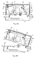
- Fig. 10A and Fig. 10B are structural diagrams schematically showing a typical example (as disclosed in Japanese unexamined patent publication HEI 1-92776) of such an image forming apparatus.
- the frame is divided into an upper and a lower frame.
- the lower frame (hereinafter called a base) 1 is provided with a paper cassette setting part 11, a paper transfer path 12, a fixing unit 13, and a pick roller and a transfer roller (not illustrated).
- the upper frame (hereinafter called a cover) 2 is provided with a photoconductive drum unit 3, a developing unit 4 and a link mechanism 5, and is rotatable around a rotating axis 14 relative to the base 1. At the interface between the base 1 and cover 2, a paper transfer path is formed.
- the cover 2 can be opened away from the base 1 at the boundary of the paper transfer path by rotation around the rotating axis 14.
- the photoconductive drum unit 3 is fixed to the cover 2 and the developing unit 4 is swayably fixed to the cover 2.
- a magnetic roller (not illustrated) within the developing unit 4 can be moved closely to or separated from a photoconductive drum 31 through such swaying operation.
- the link mechanism 5 sways the developing unit 4 in accordance with the closing and opening operation of cover 2; that is, it pivots the developing unit 4 toward or away from the photoconductive drum 31.
- the link mechanism 5 is composed of an L type rotatable arm 51, an L type transmitting arm 52 and a rotatable arm 53.
- the L type rotatable arm 51 has a guide hole 512 which engages with an engaging pin 511 provided on the base 1 at the one end thereof and rotates around a center axis 513 in accordance with the closing and opening operation of cover 2.
- the L type transmitting arm 52 couples the other end of the L type rotatable arm 51 and one end of rotatable arm 53 to realize integrated operation of these arms.
- the rotatable arm 53 rotates around a rotating axis 531 and is provided, at one end thereof, with a pushing mechanism 54 consisting of a plate spring to push the developing unit 4 toward the photoconductive drum unit 3.
- the cover 2 shown in Fig. 10A is closed toward the base 1.
- the L type rotatable arm 51 of the link mechanism 5 is rotated around the rotating axis 513 simultaneously with depression in the direction of arrow mark A.
- the transmitting arm 52 is pulled in the direction of arrow mark B and the rotatable arm 53 is driven to rotate counterclockwise around the rotating axis 531.
- the pushing mechanism 54 integrated with the rotatable arm 53 is moved to the right side, pushing the developing unit 4 toward the photoconductive drum unit 3.
- the developing unit 4 and the photoconductive drum 31 are set in a closed condition.
- the developing unit 4 is provided with a pair of gap rollers 42 which are in contact with both end portions of an external circumference of the photoconductive drum 31, the magnetic roller in the developing unit and a photosensitive drum are provided opposite each other with a constant interval (gap) between them, in the closed condition.
- the cover 2 shown in Fig. 10B is opened. Under this opened condition, the transmitting arm 52 of the link mechanism 5 is moved in the direction of arrow mark C and thereby a pushing force of the pushing mechanism 54 toward the developing unit 4 is eased. As a result, the developing unit 4 is separated from the photoconductive drum unit 3 with a recovery force of a spring (not illustrated) and, consequently, the photoconductive drum 31 is separated from the gap rollers 42.
- the image forming apparatus causes the developing unit 4 to come close to or to be separated from the photoconductive drum unit 3 in accordance with the opening and closing operations of the cover 2 and is also provided with the gear power transfer mechanism for transmitting the rotating force of drive motor to a rotating part of the developing unit 4 from the photoconductive drum unit 3 under the closed condition of these units explained above.
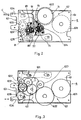
- This gear power transfer mechanism 6 is composed, as shown in Figs. 11A, 11B and Fig. 12, of a drive gear unit 62 coupled with the drive motor (not illustrated) on the side of photoconductive drum unit 3 and a driven gear unit 63 coupled with the rotating part of developing unit 4 (magnetic roller, developer agitating screw, etc.).
- the drive gear unit 62 is provided with three gears rotatably provided on a fixed substrate 61, namely a first intermediate gear 621 engaged with the drive motor, a second intermediate gear 622 always engaged with the first intermediate gear and a drive gear 623 always engaged with the second intermediate gear.
- the axis of first intermediate gear 621 is coupled with the drive mechanism of the photoconductive drum 31 and the second intermediate gear 622 is coupled with the rotating axis of a paper transfer roller (not illustrated).
- the driven gear unit 63 is composed of a movable bracket 634 (hatched area in Fig. 12) provided movably in the direction of arrow mark to the fixed substrate 61 and three gears are rotatably mounted on bracket 634.
- These three gears include a driven gear 631 engaging with the drive gear 623 on the side of photoconductive drum 31 when the developing unit 4 comes close to the photoconductive drum unit 3, a third intermediate gear 632 always engaging with the driven gear, and a fourth intermediate gear 633 always engaging with the third intermediate gear.
- the fourth intermediate gear 633 is provided with four pawls coupled with a coupling pawl gear on the side of developer 41 as shown in the figure. When these pawls couple, the magnetic roller and the developer agitating screw in the developing unit 4 are rotated.
- the gears explained above may for example be manufactured by molding synthetic resin material.
- the cover 2 shown in Fig. 11A is closed toward the base 1 and the developing unit 4 is moved toward the photoconductive drum unit 3.
- the driven gear 631 of the gear power transfer mechanism 6 engages with the drive gear 623 because both units are in the closed condition.
- a rotating force of the drive motor transmitted to the drive gear 623 through the first intermediate gear 621 and second intermediate gear 622, is further transferred sequentially to the driven gear 631, third intermediate gear 632 and fourth intermediate gear 633 from drive gear 623 to rotate the magnetic roller within the developing unit 4. Therefore, the photoconductive drum 31 and developing unit 4 are driven by the same drive motor.
- the cover 2 shown in Fig. 11B is opened and thereby the developing unit 4 is separated from the photoconductive drum unit 3.
- the driven gear 631 of the gear power transfer mechanism 6 is separated from the drive gear 623, releasing the engagement, and thereby the rotating force of drive motor is not transferred to the developer 41. Accordingly, the magnetic roller in the developing unit 4 is no longer rotated.
- the gap between the photoconductive drum 31 and developing unit 4 varies depending on minor deviations between the supporting axis of the gap rollers 42 and the rotating axis of photoconductive drum 31 which define the gap.
- This variation has a large influence on the engagement between the drive gear 623 of the drive gear unit 62 and the drive gear 631 of driven gear unit 63. That is, the positional relationship between the drive gear unit 62 and driven gear unit 63 is determined by the center axis of the gap rollers 42 of the developing unit 4 and the center of rotation of the photoconductive drum 31. If these center positions are even a little deviated, adequate engagement between the drive gear 623 and driven gear 631 can no longer be attained.
- creak is generated between gears, for example, when engagement between the drive gear 623 and driven gear 631 becomes deep, or gear missing and gear skipping are generated when engagement becomes shallow, due to relative eccentricity of the rotating axes on the side of photoconductive drum unit 3 (rotating axes of the photoconductive drum 3 and drive gear 623) and the driven axis on the side of developing unit 4 (supporting axis of gap rollers 42 and rotating axis of driven gear 631).
- an image forming apparatus having a movable developing unit which can be moved closely to and separated from a photoconductive drum of a photoconductive drum unit, and a gear power transfer mechanism which couples a first rotating axis on a side of the photoconductive drum unit and a second rotation axis on a side of the developing unit under a condition that the photoconductive drum and the developing unit are located closely, the first rotation axis being rotated by a drive motor, characterised in that: said gear power transfer mechanism comprises: a first bevel gear fixed to the first rotating axis; a second bevel gear provided so as to always engage said first bevel gear; a third bevel gear fixed to the second rotating axis; a fourth bevel gear provided so as to always engage with said third bevel gear; and rotation coupling means for serially transferring rotation of the first rotating axis to the second rotating axis by coupling said second bevel gear and said fourth bevel gear so that rotation of said second bevel gear is transferred to said fouthe bevel gear with
- An embodiment of the present invention can provide an improved gear power transfer mechanism which is always capable of transferring adequate rotating force to the rotating part of the developing unit.
- An embodiment of the present invention can also provide a gear power transfer mechanism which eliminates gap adjustment between gears, ensures easy assembling and maintenance and can easily be provided as a unit for maintenance work.
- the present invention relates to an image forming apparatus in which a developing unit is movably mounted so that it can be moved closely to or separated from a photoconductive drum, and a gear power transfer mechanism is provided so that a rotating axis on a side of a photoconductive drum unit coupled with the drive motor is coupled with a rotating axis on a side of the developing unit, under the condition that the photoconductive drum and the developing unit are in close proximity.
- the present invention more particularly concerns the structure of a gear power transfer mechanism as explained hereunder.
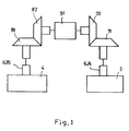
- the gear power transfer mechanism may comprise, as shown in Fig. 1, a first bevel gear 71 fixed to a rotating axis 624 on the side of the photoconductive drum unit 3, a second bevel gear 72 arranged so as to always engage the first bevel gear 71, a third bevel gear 81 fixed to the rotating axis 635 on the side of the developing unit 4, a fourth bevel gear 82 provided to always engage the third bevel gear 81, and a gear coupling means 91 engaging the second bevel gear 72 and the fourth bevel gear 82 for transferring the rotation of second bevel gear 72 to the fourth bevel gear 82 in an axis having a direction orthogonally crossing each rotating axis and for allowing the movement of fourth bevel gear 82 in the axial direction in conjunction with the movement of developing unit 4.
- the present invention has eliminated direct coupling between the drive gear and the driven gear which has been used in the prior art. Therefore, gap adjustment between the drive gear and the driven gear can be eliminated. Moreover, gear missing and gear skipping can be prevented and adequate motor power can always be transferred to the rotating part of the developing unit.
- the rotating axis 624 of drive gear 623 is coupled with the first bevel gear 71, which is always coupled with the second bevel gear 72.
- the second bevel gear 72 has a boss on a single side surface thereof. This boss is rotatably supported through a bearing 74 of an L type supporting member 73 provided on the fixed substrate 61.
- one end of rotation transfer axis 91 is fixed to an axis hole of the second bevel gear 72.
- the other end of rotation transfer axis 91 has a flat area 911 formed by cutting out a part of an external circumference and this flat area 911 is inserted into an axis hole of the fourth bevel gear 82 which will be explained later.
- the rotation axis 635 of driven gear 631 is coupled with the third bevel gear 81, which is always coupled with the fourth bevel gear 82.
- This fourth bevel gear 82 has a boss on a single side surface thereof and this boss is rotatably supported through a bearing 84 by an L type supporting member 83 provided on the movable bracket 634.
- the other end of the rotation transfer axis 91 is inserted into the axis hole of the fourth bevel gear 82. Under this insertion condition, the fourth bevel gear 82 is slidable along the rotation transfer axis 91 and it rotates together with the rotation transfer axis 91.
- the fourth bevel gear 82 can be rotated because this gear and rotation transfer axis 91 are tentatively coupled with each other by a contact force at the edge portion of flat area 911 provided at the other end of rotation transfer axis 91.
- the drive gear on the side of the photoconductive drum unit is not coupled directly with the driven gear on the side of the developing unit. Therefore, gap adjustment between these gears is unnecessary. Accordingly, the gear power transfer mechanism as a whole can be made as a single unit for easy maintenance.
- the coupling structure of the two pairs of bevel gears embraces the following two types of modifications in addition to the embodiment explained above.
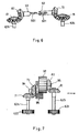
- two rotation transfer axes 92, 93 are used as shown in Fig. 6, and one of them is fixed to the second bevel gear 72 while the other is fixed to the fourth bevel gear 82.
- the free end of the first rotation transfer axis 92 fixed to the second bevel gear 72 is provided with a split groove 921
- the free end of the second rotation transfer axis 93 fixed to the fourth bevel gear 82 is provided with an engaging part 931 which may be fitted to the split groove 921.
- the second rotation transfer axis 93 may be freely moved in the axial direction and rotates together with the first rotation transfer axis 92.
- the fourth bevel gear 82 can be moved together with the movable bracket 634 and rotation of the second bevel gear 72 can be transferred to the fourth bevel gear 82 under the condition that the developing unit 4 and photoconductive drum unit 3 are located adjacently.
- the coupling can further be stabilized by fixing a cylindrical portion surrounding the coupling portion of the first rotation transfer axis 92 and the second transfer axis 93 to a side of any one of these axes.
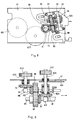
- the two pairs of bevel gears are coupled with two rotation transfer axes 94, 95.
- this embodiment is different from the previous one in that, for example, an axis center of second bevel gear 72 is deviated in the upper and horizontal directions from an axis center of fourth bevel gear 82; and the two rotation transfer axes 94, 95 to be fixed to respective axis holes are allocated in different positions; and the free end of each rotation transfer axis is provided with a pair of flat gears 96, 97 which are always engaged with each other.
- each flat gear employs a gear structure with a small number of high teeth and moreover the number of teeth of each bevel gear forming a pair is different. As shown in Fig. 8 and Fig.
- the number of teeth of the first bevel gear 71 and third bevel gear 81 is set larger than the number of teeth of the second bevel gear 72 and fourth bevel gear 82.
- the rotating axis 635 of the driven gear 631 is longer than the rotating axis 624 of the drive gear 623. Therefore, the third bevel gear 81 is located higher than the first bevel gear 71. A center area of the longer rotating axis 624 is supported by a bearing 637 for stabilizing rotation thereof.
- the movable bracket 634 is provided with a pair of supporting members 98, 99 in order to movably support the two rotation transfer axis 94, 95.
- the second bevel gear 72 and first flat gear 96 are fixed to the first rotation transfer axis 94, while the fourth bevel gear 82 and second flat gear 97 are fixed to the second rotation transfer axis 95.
- the rotating power can be transferred to the developing unit 4 from the photoconductive drum 31 as in the above two embodiments.
- This embodiment has a special effect that high accuracy is not required for positioning of opposed second bevel gear 72 and fourth bevel gear 82.
Landscapes
- Physics & Mathematics (AREA)
- General Physics & Mathematics (AREA)
- Electrophotography Configuration And Component (AREA)
- Gear Transmission (AREA)
Abstract
Claims (4)
- Appareil de formation d'image possédant une unité de développement mobile (4) qui peut être amenée à proximité d'un tambour photoconducteur (31) d'une unité de tambour photoconducteur (3) et en être séparée, et un mécanisme (6) de transmission de puissance par engrenage qui couple un premier axe de rotation (624) sur un côté de l'unité de tambour photoconducteur et un deuxième axe de rotation (635) sur un côté de l'unité de développement dans le cas où le tambour photoconducteur et l'unité de développement sont disposés de manière rapprochée, le premier axe de rotation étant entraîné en rotation par un moteur d'entraînement, caractérisé en ce que :
ledit mécanisme de transmission de puissance par engrenage comprend :- une première roue d'engrenage conique (71) fixée au premier axe de rotation (624) ;- une deuxième roue d'engrenage conique (72) prévue de manière à toujours être en prise avec ladite première roue d'engrenage conique ;- une troisième roue d'engrenage conique (81) fixée au deuxième axe de rotation (635) ;- une quatrième roue d'engrenage conique (82) prévue de façon à être toujours en prise avec ladite troisième roue d'engrenage conique ; et- un moyen de couplage de rotation (91) servant à transmettre en série la rotation du premier axe de rotation au deuxième axe de rotation par couplage de ladite deuxième roue d'engrenage conique (72) et de ladite quatrième roue d'engrenage conique (82) de façon que la rotation de ladite deuxième roue d'engrenage conique (72) soit transmise à ladite quatrième roue d'engrenage conique (82) avec un axe perpendiculaire croisant perpendiculairement lesdits premier et deuxième axes de rotation, si bien que le déplacement suivant la direction axiale dudit axe perpendiculaire est autorisé en liaison avec le déplacement de ladite unité de développement (4) par rapport au tambour photoconducteur (31). - Appareil de formation d'image selon la revendication 1, où ladite deuxième roue d'engrenage conique (72) et ladite quatrième roue d'engrenage conique (82) tournent sur un axe commun, et ledit moyen de couplage de rotation (91) comporte un unique axe de transfert de rotation, dont une extrémité est fixée à un axe de ladite deuxième roue d'engrenage conique tandis que son autre extrémité est dotée d'un élément de venue en prise (911) qui coopère avec un trou de l'axe de ladite quatrième roue d'engrenage conique (82), de façon à permettre le glissement dudit élément de venue en prise (911) par rapport à ladite quatrième roue d'engrenage conique (82) et de façon à coupler la rotation de ladite quatrième roue d'engrenage conique (82) avec la rotation de ladite deuxième roue d'engrenage conique (72).
- Appareil de formation d'image selon la revendication 1, où la deuxième roue d'engrenage conique (72) et la quatrième roue d'engrenage conique (82) tournent sur un axe commun et le moyen de couplage de rotation (91) comporte un premier axe de transmission de rotation (92) fixé par une extrémité à un axe de ladite deuxième roue d'engrenage conique et ayant un premier élément de venue en prise (921) à son autre extrémité, et un deuxième axe de transmission de rotation (93) fixé par une extrémité à un axe de ladite quatrième roue d'engrenage conique et ayant un deuxième élément de venue en prise (931) à son autre extrémité, lesdits premier et deuxième éléments de venue en prise coopérant mutuellement de façon à permettre un glissement relatif desdits premier et deuxième axes de rotation (92, 93) pour coupler la rotation de ladite quatrième roue d'engrenage conique (82) avec la rotation de ladite deuxième roue d'engrenage conique (72).
- Appareil de formation d'image selon la revendication 1, où ladite deuxième roue d'engrenage conique (72) et ladite quatrième roue d'engrenage conique (82) tournent sur des axes séparés et ledit moyen de couplage de rotation (91) comporte un premier axe de transmission de rotation (94) dont une extrémité est fixée à un axe de ladite deuxième roue d'engrenage conique, son autre extrémité étant fixée à une première roue d'engrenage droite (96), et un deuxième axe de transmission de rotation (95), parallèle au premier axe de rotation (94), dont une première extrémité est fixée à un axe de ladite quatrième roue d'engrenage conique, son autre extrémité étant fixée à une deuxième roue d'engrenage droite (97), ladite deuxième roue d'engrenage plate comportant des dents qui viennent en prise de façon coulissante avec les dents de ladite première roue d'engrenage droite.
Applications Claiming Priority (3)
| Application Number | Priority Date | Filing Date | Title |
|---|---|---|---|
| JP12719789 | 1989-05-19 | ||
| JP127197/89 | 1989-05-19 | ||
| PCT/JP1990/000619 WO1990014618A1 (fr) | 1989-05-19 | 1990-05-16 | Appareil de formation d'images |
Publications (3)
| Publication Number | Publication Date |
|---|---|
| EP0429657A1 EP0429657A1 (fr) | 1991-06-05 |
| EP0429657A4 EP0429657A4 (en) | 1993-01-20 |
| EP0429657B1 true EP0429657B1 (fr) | 1995-02-08 |
Family
ID=14954104
Family Applications (1)
| Application Number | Title | Priority Date | Filing Date |
|---|---|---|---|
| EP90907452A Expired - Lifetime EP0429657B1 (fr) | 1989-05-19 | 1990-05-16 | Appareil de formation d'images |
Country Status (4)
| Country | Link |
|---|---|
| EP (1) | EP0429657B1 (fr) |
| CA (1) | CA2028150C (fr) |
| DE (1) | DE69016751T2 (fr) |
| WO (1) | WO1990014618A1 (fr) |
Families Citing this family (1)
| Publication number | Priority date | Publication date | Assignee | Title |
|---|---|---|---|---|
| CN110568743B (zh) * | 2019-09-24 | 2024-07-05 | 珠海市汇威精密制造有限公司 | 一种驱动力接收部件及处理盒 |
Family Cites Families (2)
| Publication number | Priority date | Publication date | Assignee | Title |
|---|---|---|---|---|
| JPS62280866A (ja) * | 1986-05-30 | 1987-12-05 | Canon Inc | 画像形成装置 |
| JPH01120458A (ja) * | 1987-10-31 | 1989-05-12 | Canon Inc | 動力伝達装置 |
-
1990
- 1990-05-16 CA CA 2028150 patent/CA2028150C/fr not_active Expired - Fee Related
- 1990-05-16 WO PCT/JP1990/000619 patent/WO1990014618A1/fr not_active Ceased
- 1990-05-16 DE DE69016751T patent/DE69016751T2/de not_active Expired - Fee Related
- 1990-05-16 EP EP90907452A patent/EP0429657B1/fr not_active Expired - Lifetime
Also Published As
| Publication number | Publication date |
|---|---|
| EP0429657A4 (en) | 1993-01-20 |
| EP0429657A1 (fr) | 1991-06-05 |
| CA2028150A1 (fr) | 1990-11-20 |
| WO1990014618A1 (fr) | 1990-11-29 |
| CA2028150C (fr) | 1997-12-02 |
| DE69016751D1 (de) | 1995-03-23 |
| DE69016751T2 (de) | 1995-06-14 |
Similar Documents
| Publication | Publication Date | Title |
|---|---|---|
| DE69717220T2 (de) | Arbeitseinheit und elektrophotographisches Bilderzeugungsgerät | |
| DE69717217T2 (de) | Reinigungskassette, Reinigungsvorrichtung, Arbeitseinheit und elektrophotographisches Bilderzeugungsgerät | |
| US5319418A (en) | Image forming apparatus | |
| KR100331921B1 (ko) | 프로세스 카트리지, 그 제조방법 및 화상형성 장치 | |
| CN100495231C (zh) | 图像成形装置以及支承机构 | |
| US4947208A (en) | Process cartridge and image forming apparatus using same | |
| JPH0836346A (ja) | 画像形成装置 | |
| US5240239A (en) | Paper sheet feeding apparatus | |
| EP0389267B1 (fr) | Structure et procédé du montage des unités d'enregistrement dans un appareil d'enregistrement électrophotographique | |
| US8055155B2 (en) | Image forming apparatus with developing device support structure | |
| US6804484B2 (en) | Toner cartridge and electrophotographic apparatus adopting the same | |
| US5111245A (en) | Apparatus for positioning a development unit with respect to an image member | |
| EP0347898A3 (fr) | Appareil d'alimentation de papier utilisant des rouleaux | |
| EP0429657B1 (fr) | Appareil de formation d'images | |
| US12346057B1 (en) | Process cartridge | |
| US6978105B2 (en) | Drum assembly having helical gear and spur gear spaced therebetween for use in printer | |
| JPH06193640A (ja) | 駆動力伝達用カップリング | |
| EP0415773B1 (fr) | Appareil de formation d'images | |
| JP2526315B2 (ja) | 画像形成装置 | |
| CN223977500U (zh) | 一种显影盒和处理盒 | |
| JP2887531B2 (ja) | 現像機の取付装置 | |
| JP2540392Y2 (ja) | 電子写真装置 | |
| JPS63203943A (ja) | 回転体の回転ムラ軽減装置 | |
| JPH0416111B2 (fr) | ||
| EP0420217B1 (fr) | Appareil de formation d'images |
Legal Events
| Date | Code | Title | Description |
|---|---|---|---|
| PUAI | Public reference made under article 153(3) epc to a published international application that has entered the european phase |
Free format text: ORIGINAL CODE: 0009012 |
|
| 17P | Request for examination filed |
Effective date: 19901221 |
|
| AK | Designated contracting states |
Kind code of ref document: A1 Designated state(s): DE FR GB IT |
|
| A4 | Supplementary search report drawn up and despatched |
Effective date: 19921130 |
|
| AK | Designated contracting states |
Kind code of ref document: A4 Designated state(s): DE FR GB IT |
|
| 17Q | First examination report despatched |
Effective date: 19930526 |
|
| RBV | Designated contracting states (corrected) |
Designated state(s): DE GB |
|
| GRAA | (expected) grant |
Free format text: ORIGINAL CODE: 0009210 |
|
| AK | Designated contracting states |
Kind code of ref document: B1 Designated state(s): DE GB |
|
| REF | Corresponds to: |
Ref document number: 69016751 Country of ref document: DE Date of ref document: 19950323 |
|
| PLBE | No opposition filed within time limit |
Free format text: ORIGINAL CODE: 0009261 |
|
| STAA | Information on the status of an ep patent application or granted ep patent |
Free format text: STATUS: NO OPPOSITION FILED WITHIN TIME LIMIT |
|
| 26N | No opposition filed | ||
| PGFP | Annual fee paid to national office [announced via postgrant information from national office to epo] |
Ref country code: GB Payment date: 20000510 Year of fee payment: 11 |
|
| PGFP | Annual fee paid to national office [announced via postgrant information from national office to epo] |
Ref country code: DE Payment date: 20000515 Year of fee payment: 11 |
|
| PG25 | Lapsed in a contracting state [announced via postgrant information from national office to epo] |
Ref country code: GB Free format text: LAPSE BECAUSE OF NON-PAYMENT OF DUE FEES Effective date: 20010516 |
|
| GBPC | Gb: european patent ceased through non-payment of renewal fee |
Effective date: 20010516 |
|
| PG25 | Lapsed in a contracting state [announced via postgrant information from national office to epo] |
Ref country code: DE Free format text: LAPSE BECAUSE OF NON-PAYMENT OF DUE FEES Effective date: 20020301 |