EP0430111A2 - Senseur optique - Google Patents
Senseur optique Download PDFInfo
- Publication number
- EP0430111A2 EP0430111A2 EP90122440A EP90122440A EP0430111A2 EP 0430111 A2 EP0430111 A2 EP 0430111A2 EP 90122440 A EP90122440 A EP 90122440A EP 90122440 A EP90122440 A EP 90122440A EP 0430111 A2 EP0430111 A2 EP 0430111A2
- Authority
- EP
- European Patent Office
- Prior art keywords
- interface
- interfaces
- sensor
- liquid
- absorbent body
- Prior art date
- Legal status (The legal status is an assumption and is not a legal conclusion. Google has not performed a legal analysis and makes no representation as to the accuracy of the status listed.)
- Granted
Links
Images

Classifications
-
- G—PHYSICS
- G01—MEASURING; TESTING
- G01N—INVESTIGATING OR ANALYSING MATERIALS BY DETERMINING THEIR CHEMICAL OR PHYSICAL PROPERTIES
- G01N21/00—Investigating or analysing materials by the use of optical means, i.e. using sub-millimetre waves, infrared, visible or ultraviolet light
- G01N21/17—Systems in which incident light is modified in accordance with the properties of the material investigated
- G01N21/41—Refractivity; Phase-affecting properties, e.g. optical path length
- G01N21/43—Refractivity; Phase-affecting properties, e.g. optical path length by measuring critical angle
- G01N21/431—Dip refractometers, e.g. using optical fibres
-
- G—PHYSICS
- G01—MEASURING; TESTING
- G01F—MEASURING VOLUME, VOLUME FLOW, MASS FLOW OR LIQUID LEVEL; METERING BY VOLUME
- G01F23/00—Indicating or measuring liquid level or level of fluent solid material, e.g. indicating in terms of volume or indicating by means of an alarm
- G01F23/22—Indicating or measuring liquid level or level of fluent solid material, e.g. indicating in terms of volume or indicating by means of an alarm by measuring physical variables, other than linear dimensions, pressure or weight, dependent on the level to be measured, e.g. by difference of heat transfer of steam or water
- G01F23/28—Indicating or measuring liquid level or level of fluent solid material, e.g. indicating in terms of volume or indicating by means of an alarm by measuring physical variables, other than linear dimensions, pressure or weight, dependent on the level to be measured, e.g. by difference of heat transfer of steam or water by measuring the variations of parameters of electromagnetic or acoustic waves applied directly to the liquid or fluent solid material
- G01F23/284—Electromagnetic waves
- G01F23/292—Light, e.g. infrared or ultraviolet
-
- G—PHYSICS
- G01—MEASURING; TESTING
- G01F—MEASURING VOLUME, VOLUME FLOW, MASS FLOW OR LIQUID LEVEL; METERING BY VOLUME
- G01F23/00—Indicating or measuring liquid level or level of fluent solid material, e.g. indicating in terms of volume or indicating by means of an alarm
- G01F23/22—Indicating or measuring liquid level or level of fluent solid material, e.g. indicating in terms of volume or indicating by means of an alarm by measuring physical variables, other than linear dimensions, pressure or weight, dependent on the level to be measured, e.g. by difference of heat transfer of steam or water
- G01F23/28—Indicating or measuring liquid level or level of fluent solid material, e.g. indicating in terms of volume or indicating by means of an alarm by measuring physical variables, other than linear dimensions, pressure or weight, dependent on the level to be measured, e.g. by difference of heat transfer of steam or water by measuring the variations of parameters of electromagnetic or acoustic waves applied directly to the liquid or fluent solid material
- G01F23/284—Electromagnetic waves
- G01F23/292—Light, e.g. infrared or ultraviolet
- G01F23/2921—Light, e.g. infrared or ultraviolet for discrete levels
- G01F23/2922—Light, e.g. infrared or ultraviolet for discrete levels with light-conducting sensing elements, e.g. prisms
-
- G—PHYSICS
- G01—MEASURING; TESTING
- G01N—INVESTIGATING OR ANALYSING MATERIALS BY DETERMINING THEIR CHEMICAL OR PHYSICAL PROPERTIES
- G01N21/00—Investigating or analysing materials by the use of optical means, i.e. using sub-millimetre waves, infrared, visible or ultraviolet light
- G01N21/01—Arrangements or apparatus for facilitating the optical investigation
- G01N21/15—Preventing contamination of the components of the optical system or obstruction of the light path
- G01N2021/158—Eliminating condensation
Definitions
- the invention relates to an optical sensor of the type mentioned in the preamble of claim 1.
- Such sensors which are used to detect liquids, are e.g. B. arranged above a liquid level and generate a signal when they come into contact with their optical interface with the liquid level. Since the refractive index of the liquid is different from that of the surrounding air, the reflective properties of the optical interface change for the light coupled into the sensor body. The arrangement can be such that the optical interface totally reflects the light when it is outside the liquid, while the light passes completely or partially when immersed in the liquid. This clear criterion can be used to determine a liquid level.
- the object of the present invention is to take measures which prevent this drop formation in order to avoid or at least reduce the signal falsification or influencing.
- This object is achieved according to the basic idea of the invention in that in the area of the interface an element which absorbs the liquid layer or the drop, namely an absorbent body, is provided, but is designed and arranged such that the passage of light through the interface does not or not is significantly affected.
- This capillary or pore absorbent body must be selected and dimensioned such that its capillary force is greater than the surface tension acting on the liquid layer at the interface.
- a sensor body made of sintered glass frit is suitable for a sensor body made of glass.
- the absorbent body can also have one or more capillary tubes, as indicated in claim 4.
- the suction body is advantageously arranged according to claim 2 in front of or under the structure tip.
- the suction bodies which are designed to be slender compared to the interfaces, absorb the liquid wetting the interface and discharge it at the ends, preferably tapered, away from the interfaces.
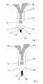
- the sensor essentially consists of a translucent sensor body 10 made of glass or synthetic glass.
- Light 30, which is generated by a light source (not shown) and is preferably supplied with a light guide, is coupled in via coupling surface 14. This light is reflected at the optical interfaces 11, 12, which is indicated by the arrow 31. At 32 the light exits and is fed to a detector, not shown.
- the optical interfaces 11 and 12 are arranged in such a way that total reflection takes place when the sensor body 10 is in a gaseous atmosphere, preferably in air.
- the sensor body 10 If, on the other hand, the sensor body 10 is immersed with its interfaces 11 and 12 in a liquid medium, the refractive angle changes with the result that part of the light impinging on the optical interfaces 11 and 12 passes through them and a smaller amount is reflected to the detector 32 . This effect can therefore be used to determine the level of liquids.
- Signal falsification occurs, however, if a liquid layer 21 is deposited on the interfaces 11, 12 and drops 20 are formed. This disruptive wetting occurs when the sensor body 10 is in a vapor-saturated atmosphere, which can arise above the liquid level to be checked.
- this absorbent body 40 which is arranged below the structural tip 13 at a smaller distance, consists of porous material, namely sintered glass frit.
- the capillary forces of the absorbent body acting on the precipitating liquid pores are larger than the opposing surface tension, with the result that the interfaces 11 and 12 are not wetted by a liquid layer.
- This liquid layer is dispensed in the form of drops 20 at the tapered end 41 of the absorbent body 40.
- the absorbent body 40 has a small cross section compared to the interfaces 11 and 12, so that the passage of light through the interfaces 11 and 12 is not significantly restricted.
- a capillary tube 50 serves as the absorbent body.
- the liquid taken up via the capillary is also dispensed in the form of drops 22 at the tapered end 51 in this arrangement.
- FIG. 4 A third modification of this proposal is illustrated in FIG. 4, in which the absorbent body consists of a tube 60 which has a plurality of tubular or column-shaped capillaries running parallel to one another, at the end of which the absorbed liquid in the form of drops 23 is also dispensed becomes.
Landscapes
- Physics & Mathematics (AREA)
- Electromagnetism (AREA)
- General Physics & Mathematics (AREA)
- Fluid Mechanics (AREA)
- Thermal Sciences (AREA)
- Analytical Chemistry (AREA)
- General Health & Medical Sciences (AREA)
- Biochemistry (AREA)
- Immunology (AREA)
- Pathology (AREA)
- Chemical & Material Sciences (AREA)
- Life Sciences & Earth Sciences (AREA)
- Health & Medical Sciences (AREA)
- Investigating Or Analysing Materials By Optical Means (AREA)
- Measurement Of Levels Of Liquids Or Fluent Solid Materials (AREA)
- Investigating Or Analysing Materials By The Use Of Chemical Reactions (AREA)
- Glass Compositions (AREA)
- Gyroscopes (AREA)
Applications Claiming Priority (2)
| Application Number | Priority Date | Filing Date | Title |
|---|---|---|---|
| DE3939167A DE3939167A1 (de) | 1989-11-27 | 1989-11-27 | Optischer sensor |
| DE3939167 | 1989-11-27 |
Publications (3)
| Publication Number | Publication Date |
|---|---|
| EP0430111A2 true EP0430111A2 (fr) | 1991-06-05 |
| EP0430111A3 EP0430111A3 (en) | 1992-05-13 |
| EP0430111B1 EP0430111B1 (fr) | 1995-06-14 |
Family
ID=6394270
Family Applications (1)
| Application Number | Title | Priority Date | Filing Date |
|---|---|---|---|
| EP90122440A Expired - Lifetime EP0430111B1 (fr) | 1989-11-27 | 1990-11-24 | Senseur optique |
Country Status (3)
| Country | Link |
|---|---|
| EP (1) | EP0430111B1 (fr) |
| AT (1) | ATE123874T1 (fr) |
| DE (2) | DE3939167A1 (fr) |
Cited By (4)
| Publication number | Priority date | Publication date | Assignee | Title |
|---|---|---|---|---|
| WO1999035471A1 (fr) * | 1998-01-09 | 1999-07-15 | Scully Signal Company | Sonde anti-debordement pour fluides a element de protection anti-reflet |
| DE4242927B4 (de) * | 1992-12-18 | 2004-03-18 | Bauknecht Hausgeräte GmbH | Optischer Sensor |
| JP2009079974A (ja) * | 2007-09-26 | 2009-04-16 | Niigata Univ | アルコール濃度センサ |
| DE102008056701A1 (de) | 2008-11-11 | 2010-06-17 | Emz-Hanauer Gmbh & Co. Kgaa | Optischer Schaumsensor |
Family Cites Families (5)
| Publication number | Priority date | Publication date | Assignee | Title |
|---|---|---|---|---|
| AT21555B (de) * | 1904-02-26 | 1905-10-10 | Leo Mischel | Briefumschlag. |
| DE2505485A1 (de) * | 1975-02-10 | 1976-08-19 | Helmut Dipl Chem Ulrich | Fuellstandsanzeiger oder zustandsdetektor |
| DE2824807A1 (de) * | 1978-06-06 | 1979-12-13 | Benno Perren | Elektro-optisches geraet fuer den nachweis des vorhandenseins von fluessigkeit |
| DE7816970U1 (de) * | 1978-06-06 | 1978-11-02 | Perren, Benno, Wettingen, Aargau (Schweiz) | Elektro-optisches geraet fuer den nachweis des vorhandenseins von fluessigkeit |
| US4764671A (en) * | 1986-10-03 | 1988-08-16 | Kollmorgen Corporation | Fiber optic fluid sensor using coated sensor tip |
-
1989
- 1989-11-27 DE DE3939167A patent/DE3939167A1/de not_active Withdrawn
-
1990
- 1990-11-24 AT AT90122440T patent/ATE123874T1/de active
- 1990-11-24 DE DE59009236T patent/DE59009236D1/de not_active Expired - Fee Related
- 1990-11-24 EP EP90122440A patent/EP0430111B1/fr not_active Expired - Lifetime
Cited By (6)
| Publication number | Priority date | Publication date | Assignee | Title |
|---|---|---|---|---|
| DE4242927B4 (de) * | 1992-12-18 | 2004-03-18 | Bauknecht Hausgeräte GmbH | Optischer Sensor |
| WO1999035471A1 (fr) * | 1998-01-09 | 1999-07-15 | Scully Signal Company | Sonde anti-debordement pour fluides a element de protection anti-reflet |
| US6049088A (en) * | 1998-01-09 | 2000-04-11 | Scully Signal Company | Fluid overfill probe with anti-reflective guard |
| JP2009079974A (ja) * | 2007-09-26 | 2009-04-16 | Niigata Univ | アルコール濃度センサ |
| DE102008056701A1 (de) | 2008-11-11 | 2010-06-17 | Emz-Hanauer Gmbh & Co. Kgaa | Optischer Schaumsensor |
| DE102008056701B4 (de) * | 2008-11-11 | 2011-02-17 | Emz-Hanauer Gmbh & Co. Kgaa | Optischer Schaumsensor |
Also Published As
| Publication number | Publication date |
|---|---|
| EP0430111B1 (fr) | 1995-06-14 |
| EP0430111A3 (en) | 1992-05-13 |
| DE3939167A1 (de) | 1991-05-29 |
| DE59009236D1 (de) | 1995-07-20 |
| ATE123874T1 (de) | 1995-06-15 |
Similar Documents
| Publication | Publication Date | Title |
|---|---|---|
| EP0987539B1 (fr) | Système de mesure avec au moins une source d'excitation | |
| EP0078939B1 (fr) | Dispositif en forme de bâton pour détecter le niveau respectif de liquides dans des récipients, des canaux ou similaires | |
| EP0641599B1 (fr) | Procédé et dispositif de mesure d'un volume de liquide | |
| EP0582082B1 (fr) | Procédé pour déterminer la viscosité de liquides et utilisation d'un dispositif mettant en oeuvre ce procédé | |
| DE10035263C2 (de) | Optische Vorrichtung | |
| EP0619476A1 (fr) | Dispositif pour la détection d'un interface fluidique dans un tube de mesure transparent | |
| DE3802535A1 (de) | Vorrichtung zur betrachtung insbesondere von rohedelsteinen in einer immersionsfluessigkeit | |
| EP0019871B1 (fr) | Cuvette pour l'examen optique de fluides | |
| DE3344387A1 (de) | Photometerkopf fuer kleine messvolumina | |
| EP0450174A1 (fr) | Dispositif de mesurage opto-électrique du niveau d'interface et de l'indice de réfraction dans des fluides | |
| DE69705937T2 (de) | Optisches gerät | |
| DE3606847A1 (de) | Faseroptischer sensor fuer fluessigkeitsstandanzeiger oder -niveauregler | |
| EP0430111B1 (fr) | Senseur optique | |
| DE3887139T2 (de) | Optischer flüssigkeitsspiegel-sensor. | |
| DE2922643C2 (fr) | ||
| DE10221823A1 (de) | Verfahren und Vorrichtung zur Messung der Höhe des Flüssigkeitsniveaus und des Verunreinigungsgrades von Wassern und anderen transparenten Flüssigkeiten | |
| DE3030856C2 (fr) | ||
| DE19924259C2 (de) | Vorrichtung und Verfahren zur Erfassung des Füllstandes eines Flüssigkeitsbehälters | |
| DE4133126C2 (de) | Feuchtesensor | |
| DE4001954C2 (fr) | ||
| WO2012038346A1 (fr) | Capteur destiné à la surveillance d'un milieu | |
| DE3617717C2 (de) | Faseroptischer Füllstandssensor | |
| EP0199312B1 (fr) | Procédé et dispositif de détermination du frottement superficiel ou de la viscosité d'un liquide sur un modèle ou autre objet en contact avec l'écoulement | |
| DE3539308C2 (fr) | ||
| DE4300290A1 (fr) |
Legal Events
| Date | Code | Title | Description |
|---|---|---|---|
| PUAI | Public reference made under article 153(3) epc to a published international application that has entered the european phase |
Free format text: ORIGINAL CODE: 0009012 |
|
| AK | Designated contracting states |
Kind code of ref document: A2 Designated state(s): AT BE CH DE ES FR GB IT LI NL SE |
|
| PUAL | Search report despatched |
Free format text: ORIGINAL CODE: 0009013 |
|
| AK | Designated contracting states |
Kind code of ref document: A3 Designated state(s): AT BE CH DE ES FR GB IT LI NL SE |
|
| 17P | Request for examination filed |
Effective date: 19920703 |
|
| 17Q | First examination report despatched |
Effective date: 19940722 |
|
| GRAA | (expected) grant |
Free format text: ORIGINAL CODE: 0009210 |
|
| AK | Designated contracting states |
Kind code of ref document: B1 Designated state(s): AT BE CH DE ES FR GB IT LI NL SE |
|
| PG25 | Lapsed in a contracting state [announced via postgrant information from national office to epo] |
Ref country code: IT Free format text: LAPSE BECAUSE OF FAILURE TO SUBMIT A TRANSLATION OF THE DESCRIPTION OR TO PAY THE FEE WITHIN THE PRE;WARNING: LAPSES OF ITALIAN PATENTS WITH EFFECTIVE DATE BEFORE 2007 MAY HAVE OCCURRED AT ANY TIME BEFORE 2007. THE CORRECT EFFECTIVE DATE MAY BE DIFFERENT FROM THE ONE RECORDED.SCRIBED TIME-LIMIT Effective date: 19950614 Ref country code: GB Effective date: 19950614 Ref country code: FR Effective date: 19950614 Ref country code: ES Free format text: THE PATENT HAS BEEN ANNULLED BY A DECISION OF A NATIONAL AUTHORITY Effective date: 19950614 Ref country code: BE Effective date: 19950614 Ref country code: NL Free format text: LAPSE BECAUSE OF NON-PAYMENT OF DUE FEES Effective date: 19950614 |
|
| REF | Corresponds to: |
Ref document number: 123874 Country of ref document: AT Date of ref document: 19950615 Kind code of ref document: T |
|
| REF | Corresponds to: |
Ref document number: 59009236 Country of ref document: DE Date of ref document: 19950720 |
|
| PG25 | Lapsed in a contracting state [announced via postgrant information from national office to epo] |
Ref country code: SE Effective date: 19950914 |
|
| EN | Fr: translation not filed | ||
| PG25 | Lapsed in a contracting state [announced via postgrant information from national office to epo] |
Ref country code: AT Effective date: 19951124 |
|
| PG25 | Lapsed in a contracting state [announced via postgrant information from national office to epo] |
Ref country code: CH Effective date: 19951130 Ref country code: LI Effective date: 19951130 |
|
| GBV | Gb: ep patent (uk) treated as always having been void in accordance with gb section 77(7)/1977 [no translation filed] |
Effective date: 19950614 |
|
| NLV1 | Nl: lapsed or annulled due to failure to fulfill the requirements of art. 29p and 29m of the patents act | ||
| PLBE | No opposition filed within time limit |
Free format text: ORIGINAL CODE: 0009261 |
|
| STAA | Information on the status of an ep patent application or granted ep patent |
Free format text: STATUS: NO OPPOSITION FILED WITHIN TIME LIMIT |
|
| 26N | No opposition filed | ||
| REG | Reference to a national code |
Ref country code: CH Ref legal event code: PL |
|
| PGFP | Annual fee paid to national office [announced via postgrant information from national office to epo] |
Ref country code: DE Payment date: 19961221 Year of fee payment: 7 |
|
| PG25 | Lapsed in a contracting state [announced via postgrant information from national office to epo] |
Ref country code: DE Free format text: LAPSE BECAUSE OF NON-PAYMENT OF DUE FEES Effective date: 19980801 |