EP0430203A2 - Steuerungssystem für Fahrzeugwechselstromgenerator - Google Patents
Steuerungssystem für Fahrzeugwechselstromgenerator Download PDFInfo
- Publication number
- EP0430203A2 EP0430203A2 EP90122741A EP90122741A EP0430203A2 EP 0430203 A2 EP0430203 A2 EP 0430203A2 EP 90122741 A EP90122741 A EP 90122741A EP 90122741 A EP90122741 A EP 90122741A EP 0430203 A2 EP0430203 A2 EP 0430203A2
- Authority
- EP
- European Patent Office
- Prior art keywords
- generator
- voltage
- output
- engine
- battery
- Prior art date
- Legal status (The legal status is an assumption and is not a legal conclusion. Google has not performed a legal analysis and makes no representation as to the accuracy of the status listed.)
- Granted
Links
Images
Classifications
-
- H—ELECTRICITY
- H02—GENERATION; CONVERSION OR DISTRIBUTION OF ELECTRIC POWER
- H02J—ELECTRIC POWER NETWORKS; CIRCUIT ARRANGEMENTS OR SYSTEMS FOR SUPPLYING OR DISTRIBUTING ELECTRIC POWER; SYSTEMS FOR STORING ELECTRIC ENERGY
- H02J7/00—Circuit arrangements for charging or discharging batteries or for supplying loads from batteries
- H02J7/14—Circuit arrangements for charging or discharging batteries or for supplying loads from batteries for charging batteries from dynamo-electric generators driven at varying speed, e.g. on vehicle
- H02J7/1446—Circuit arrangements for charging or discharging batteries or for supplying loads from batteries for charging batteries from dynamo-electric generators driven at varying speed, e.g. on vehicle in response to parameters of a vehicle
-
- H—ELECTRICITY
- H02—GENERATION; CONVERSION OR DISTRIBUTION OF ELECTRIC POWER
- H02J—ELECTRIC POWER NETWORKS; CIRCUIT ARRANGEMENTS OR SYSTEMS FOR SUPPLYING OR DISTRIBUTING ELECTRIC POWER; SYSTEMS FOR STORING ELECTRIC ENERGY
- H02J7/00—Circuit arrangements for charging or discharging batteries or for supplying loads from batteries
- H02J7/14—Circuit arrangements for charging or discharging batteries or for supplying loads from batteries for charging batteries from dynamo-electric generators driven at varying speed, e.g. on vehicle
- H02J7/16—Regulation of the charging current or voltage by variation of field
- H02J7/24—Regulation of the charging current or voltage by variation of field using discharge tubes or semiconductor devices
- H02J7/2434—Regulation of the charging current or voltage by variation of field using discharge tubes or semiconductor devices with pulse modulation
-
- Y—GENERAL TAGGING OF NEW TECHNOLOGICAL DEVELOPMENTS; GENERAL TAGGING OF CROSS-SECTIONAL TECHNOLOGIES SPANNING OVER SEVERAL SECTIONS OF THE IPC; TECHNICAL SUBJECTS COVERED BY FORMER USPC CROSS-REFERENCE ART COLLECTIONS [XRACs] AND DIGESTS
- Y02—TECHNOLOGIES OR APPLICATIONS FOR MITIGATION OR ADAPTATION AGAINST CLIMATE CHANGE
- Y02T—CLIMATE CHANGE MITIGATION TECHNOLOGIES RELATED TO TRANSPORTATION
- Y02T10/00—Road transport of goods or passengers
- Y02T10/60—Other road transportation technologies with climate change mitigation effect
- Y02T10/70—Energy storage systems for electromobility, e.g. batteries
-
- Y—GENERAL TAGGING OF NEW TECHNOLOGICAL DEVELOPMENTS; GENERAL TAGGING OF CROSS-SECTIONAL TECHNOLOGIES SPANNING OVER SEVERAL SECTIONS OF THE IPC; TECHNICAL SUBJECTS COVERED BY FORMER USPC CROSS-REFERENCE ART COLLECTIONS [XRACs] AND DIGESTS
- Y02—TECHNOLOGIES OR APPLICATIONS FOR MITIGATION OR ADAPTATION AGAINST CLIMATE CHANGE
- Y02T—CLIMATE CHANGE MITIGATION TECHNOLOGIES RELATED TO TRANSPORTATION
- Y02T10/00—Road transport of goods or passengers
- Y02T10/80—Technologies aiming to reduce greenhouse gasses emissions common to all road transportation technologies
- Y02T10/92—Energy efficient charging or discharging systems for batteries, ultracapacitors, supercapacitors or double-layer capacitors specially adapted for vehicles
Definitions
- This invention relates to a vehicle AC generator control system.
- the above-described control device controls the field current for a certain period of time from the start of the engine, as was described above. Therefore, the generator output is suppressed, but it will not become zero (A). Hence, with the device, it is difficult to completely eliminate the generator drive load torque; that is, the rotation of engine cannot be sufficiently stabilized.
- the conventional control device a certain period of time from the start of the engine the field current is abruptly increased, and accordingly the generator output is also abruptly increased; that is, the engine load is abruptly increased, so that the belt slip noise is liable to be produced.
- the abrupt increase of the engine load may adversely affect the rotation of the engine.
- an object of this invention is to eliminate the above-described difficulties accompanying a'conventional control drive for a vehicle AC generator.
- an object of the invention is to provide a control device for a vehicle AC generator in which the generator drive load torque is completely eliminated which otherwise occurs immediately after the start of the engine, to stabilize the rotation of the engine, and the production of a belt slip noise is prevented when it is cold, and in which the production of a belt slip noise and the decrease in the speed of rotation of the engine are prevented which otherwise may be caused when the generator output is restored.
- a vehicle AC generator control system comprising an AC generator having a field coil, a rectifier for rectifying an AC output of the AC generator, a battery connected to the output terminals of the rectifier and a voltage regulator having a switching element connected in series to the field coil, the voltage regulator detecting the terminal voltage of either the rectifier or battery, to control a field current with the aid of the switching element, to adjust an output voltage of the AC generator to a predetermined value.
- the voltage regulator operates to adjust the output voltage of the AC generator to a first value lower than a voltage appearing across the battery during a predetermined period of time after the start of power generation of said AC generator and then to a second value higher than the battery output voltage after the predetermined period has elapsed.
- the voltage regulator operates to control said switching element so as to have a first conduction rate for a predetermined period of time from the start of power generation by said AC generator, and then to control said switching element so as to have a conduction rate gradually increasing from the first conduction rate to a second conduction rate.
- the generated voltage is adjusted to a value lower than the battery voltage for the predetermined period of time from the start of power generation, and thereafter to a value higher than the battery voltage so that the usual charge output operation is carried out.
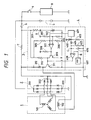
- Fig. 1 is a circuit diagram showing an example of a vehicle AC generator control system
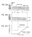
- Figs. 2(a) to 2(b) are graphical representations for a description of the operation of the control device.
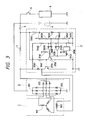
- Fig. 3 is a circuit diagram showing another example of a vehicle AC generator control system according to the present invention.
- an AC generator 1 has an armature coil 101 and a field coil 102, and is connected to a rectifier 2.
- the rectifier 2 has a main output terminal 201, an auxiliary output terminal 202, and a grounding terminal 203.
- a voltage regulator 3 which comprises: a constant voltage source A including a resistor 301 and a Zener diode 302; a reference voltage circuit including voltage dividing resistors 303 and 304 for dividing the voltage of the constant voltage source A to provide a reference voltage; voltage dividing resistors 305 and 306 for detecting a generator output voltage; a comparator 307 for comparing a generator output voltage with the reference voltage; a control transistor 309 whose base is connected to the output terminal of the comparator 307 and through a resistor 309 to the constant voltage source A; a power transistor 311 to which a base current is applied through a resistor 310, the power transistor 311 being turned on and off by the control transistor 309; and a suppression diode 312 connected in parallel to the field coil to absorb surge current.
- a field current controller 4 which comprises: a timer 401 connected to the voltage dividing resistors 305 and 306 which detect a generator output voltage, the timer 401 being started upon detection of the generator output; a reference voltage circuit including voltage dividing resistors 402 and 403; a diode 404; a time constant circuit including a resistor 405 and a capacitor 406; a triangular wave generator 407 for generating a triangular wave having a predetermined period; and a comparator 408 for comparing the voltage at the circuit point B in Fig. 1 which is the output triangular wave signal of the triangular wave generator 407 with the voltage at the circuit point C in Fig. 1 which is the output signal of the time constant circuit.
- the output terminal of the field current controller 4 is connected to the base of the power transistor 311 in the voltage regulator 3.
- the main output terminal 201 and the auxiliary output terminal 202 of the rectifier 2 are connected to a battery 5.
- One end of the field coil 102 is connected through a key switch 6 to the battery 5, and the other end is connected to the voltage regulator 3.
- the comparator 307 compares a generator output voltage with the reference voltage so that the generated voltage reaches a predetermined value.
- the timer 401 After detecting the start of power generation of the generator, outputs a high level signal for a period of time T1 (Fig. 2), and a low level signal thereafter.
- the generated voltage controlled according to the result of comparison of the voltage at the circuit point C (hereinafter referred to as "a point C voltage”, when applicable) which is determined by the voltage dividing resistors 402 and 403 with the voltage at the circuit point B (hereinafter referred to as “a point B voltage”, when applicable) which is the triangular wave signal, is so set as to be lower than the battery voltage.
- the voltage at the circuit point C (hereinafter referred to as "a point C voltage”, when applicable) is so set that it is lowered by the time constant circuit consisting of the capacitor 406 and the resistor 405 to a predetermined level in a predetermined period of time T2 as indicated by the broken line in Fig. 2(a).
- the generator 1 When the key switch 6 is turned on, the generator 1 has not started its power generation yet, and therefore the output of the comparator 307 in the voltage regulator 3 is at low level, and the output of the timer 401 in the field current controller 4 is also at low level. Hence, the output of the comparator 408 in the field current controller 4 is at high level, so that the power transistor 311 is rendered conductive (on) to allow an initial exciting current to flow in the field coil 102 through an initial exciting resistor 7.
- the generator 1 starts power generation being driven by the engine, the output of the timer 401 is raised to high level, so that a time measuring operation is carried out. For the predetermined period of time T1 that the timer 401 is in operation, the point C voltage is at the level set by the voltage dividing resistors 402 and 403.
- the level thus set relates to the triangular wave signal at the circuit point B as indicated in Fig. 2(a). These values are subjected to comparison by the comparator 408 in the field current controller 4, and in response to the result of comparison the power transistor 311 is rendered on and off as shown in Fig. 2(b). In this operation, the percentage of conduction of the power transistor is minimum, and in this case the generated voltage is not higher than the battery voltage. Hence, the output of the generator 1 is zero (0) for the predetermined period of time T1 as shown in the part (c) of Fig. 2.
- the point C voltage is decreased to a predetermined level taking the time T2 determined by the time constant circuit consisting of the capacitor 406 and the resistor 405 as shown in Fig. 2(a).
- the waveform of conduction of the power transistor 311 operating in response to the result of comparison by the comparator 408 is as shown in Fig. 2(b). That is, the percentage of conduction of the power transistor 311 is gradually increased, and reaches the maximum value 100% in the predetermined period of time T2.
- the output of the generator is gradually increased from 0% to 100% as indicated by the solid line in Fig. 2(c).
- the original control is carried out according to the output of the comparator 307 in the voltage regulator 3.
- the solid line indicates the variations of the generator output with the conventional control device.
- the generated voltage is set lower than the battery voltage so that the generator provides no output.
- the generator drive load torque can be completely eliminated to quickly stabilize the engine idling rotation.
- the production of a belt slip noise can be prevented at low temperatures.
- the percentage of conduction of the switching element is gradually increased in the predetermined period of time, and therefore the engine load will not be abruptly increased. Accordingly, the production of belt slip noises and the reduction of the speed of rotation of the engine can be positively prevented which otherwise take place when the generator output is restored.
- the field coil 102 is connected to a voltage regulator 3 which controls the field current thereby to control the output voltage of the AC generator.
- the voltage regulator 3 comprises: a constant voltage source A including a resistor 3010 and a Zener diode 3020; a reference voltage circuit including voltage dividing resistors 3030, 3040 and 3050 for dividing the output of the constant voltage source A to provide first and second reference voltages; voltage dividing resistors 3060 and 3070 for detecting an output voltage of the generator; a first comparator 3080 for comparing a generator output voltage with the first reference voltage provided by the reference voltage circuit; a second comparator 3090 for comparing a generator output voltage with the second reference voltage provided by the reference voltage circuit; a timer connected to the voltage dividing resistors 3060 and 3070, said timer being started upon detection of a predetermined output voltage; resistors 3110 and 3120 connected to the constant voltage source A; a control transistor whose base is connected through a diode 3130 to the resistor 3110 (connected to the constant voltage source A) and the output terminal of the first comparator 3080, and connected to the output terminal of the second comparator 3090, and
- the main output terminal 201 and the auxiliary output terminal 202 of the rectifier 2 are connected to a battery 4.
- One end of the field coil 102 is connected through an initial exciting resistor 7 and a key switch 6 to the battery 4, and the other end is connected to the voltage regulator 3.
- a vehicle electrical load 8 is connected through a load switch 9 to the battery 4.
- the vehicle AC generator is of 12V.
- the battery voltage is 12V.
- the second comparator 3090 determines whether or not the generator output voltage reaches a first predetermined value such as 10V, while the first comparator 3080 determines whether or not the generator output voltage reaches a second predetermined value such as 14V.
- the timer 3100 is started when the generator output voltage reaches, for instance, 8V, the timer 3100 is started to outputs a high level signal for a predetermined period of time, for instance ten (10) seconds, and a low level signal thereafter.
- the generator 1 starts power generation being driven by the engine.
- the output of the timer 3100 is raised to high level, thus starting the measurement of time.
- the output of the second comparator 3090 is raise to high level.
- the control transistor 3150 is rendered conductive (on), and therefore the power transistor 3170 is rendered non-conductive (off), thereby to prevent the rise of the output voltage.
- the output of the second comparator 3090 is set to low level.
- control transistor 3150 is rendered non-conductive (off), and accordingly the power transistor 3170 is rendered conductive (on), thus preventing the fall of the output voltage.
- the generator output voltage is maintained at 10V for the ten seconds the timer 3100 is in operation.
- the output of the timer 3100 is set to low level, so that the control transistor 3150 is rendered non-conductive (off) and the power transistor 3170 is rendered conductive (on).
- the exciting current is increased, and the generated voltage is also increased.
- the output of the first comparator 308 is raised to high level, as a result of which the control transistor 3150 is rendered conductive, and therefore the power transistor 3170 is rendered non-conductive, thus suppressing the field current to prevent the rise of the generated voltage.
- the generated voltage becomes lower than 14V
- output of the first comparator 3080 is set to low level.
- the control transistor 3150 is rendered non-conductive, and therefore the power transistor 3170 is rendered conductive, thus increasing the field current to prevent the fall of the output voltage.
- the generated voltage is maintained at 14V.
- the generated voltage is adjusted to 10V lower than the battery voltage for ten seconds from the start of power generation by the generator; that is, the generator 1 provides no output.
- the generated voltage is adjusted to 14V higher than the battery voltage, so that the usual charge output operation is carried out.
- the operating time of the timer 3100 is ten seconds; however, the invention is not limited thereto or thereby. That is, the operating time may be set to other values as the case may be.
- the generator drive load torque can be completely eliminated, to quickly stabilize the engine idling rotation.
Landscapes
- Engineering & Computer Science (AREA)
- Power Engineering (AREA)
- Control Of Eletrric Generators (AREA)
- Control Of Charge By Means Of Generators (AREA)
Priority Applications (1)
| Application Number | Priority Date | Filing Date | Title |
|---|---|---|---|
| EP97108381A EP0963027B1 (de) | 1989-11-30 | 1990-11-28 | Steuerungssystem für einen Wechselstromgenerator eines Kraftfahrzeuges |
Applications Claiming Priority (4)
| Application Number | Priority Date | Filing Date | Title |
|---|---|---|---|
| JP313853/89 | 1989-11-30 | ||
| JP313854/89 | 1989-11-30 | ||
| JP1313853A JP3004296B2 (ja) | 1989-11-30 | 1989-11-30 | 車両用交流発電機の制御装置 |
| JP31385489A JPH03173325A (ja) | 1989-11-30 | 1989-11-30 | 車両用交流発電機の制御装置 |
Related Child Applications (1)
| Application Number | Title | Priority Date | Filing Date |
|---|---|---|---|
| EP97108381A Division EP0963027B1 (de) | 1989-11-30 | 1990-11-28 | Steuerungssystem für einen Wechselstromgenerator eines Kraftfahrzeuges |
Publications (3)
| Publication Number | Publication Date |
|---|---|
| EP0430203A2 true EP0430203A2 (de) | 1991-06-05 |
| EP0430203A3 EP0430203A3 (en) | 1992-03-18 |
| EP0430203B1 EP0430203B1 (de) | 1997-09-03 |
Family
ID=26567734
Family Applications (2)
| Application Number | Title | Priority Date | Filing Date |
|---|---|---|---|
| EP90122741A Expired - Lifetime EP0430203B1 (de) | 1989-11-30 | 1990-11-28 | Steuerungssystem für Fahrzeugwechselstromgenerator |
| EP97108381A Expired - Lifetime EP0963027B1 (de) | 1989-11-30 | 1990-11-28 | Steuerungssystem für einen Wechselstromgenerator eines Kraftfahrzeuges |
Family Applications After (1)
| Application Number | Title | Priority Date | Filing Date |
|---|---|---|---|
| EP97108381A Expired - Lifetime EP0963027B1 (de) | 1989-11-30 | 1990-11-28 | Steuerungssystem für einen Wechselstromgenerator eines Kraftfahrzeuges |
Country Status (4)
| Country | Link |
|---|---|
| US (1) | US5144220A (de) |
| EP (2) | EP0430203B1 (de) |
| DE (2) | DE69031374T2 (de) |
| HK (1) | HK1003041A1 (de) |
Cited By (14)
| Publication number | Priority date | Publication date | Assignee | Title |
|---|---|---|---|---|
| EP0559555A1 (de) * | 1992-03-03 | 1993-09-08 | Valeo Equipements Electriques Moteur | Verbesserter störungsunterdrückender Wechselstromgenerator, insbesondere für Kraftfahrzeuge |
| EP0577987A3 (de) * | 1992-07-04 | 1994-10-12 | Bosch Gmbh Robert | Einrichtung zur Regelung der Ausgangsspannung eines von einer Brennkraftmaschine angetriebenen Generators. |
| FR2728405A1 (fr) * | 1994-12-19 | 1996-06-21 | Valeo Equip Electr Moteur | Dispositif regulateur de la tension de charge d'une batterie par un alternateur, avec regulation prioritaire au demarrage, notamment pour vehicule automobile |
| FR2730360A1 (fr) * | 1995-02-03 | 1996-08-09 | Valeo Equip Electr Moteur | Ensemble de regulation de la tension de sortie d'un alternateur, notamment dans un vehicule automobile |
| EP0762595A3 (de) * | 1995-09-06 | 1997-09-17 | Mitsubishi Electric Corp | Steuerungsvorrichtung für Wechselstromgenerator |
| EP0751602A3 (de) * | 1995-06-23 | 1998-01-21 | Denso Corporation | Regelungssystem für einen Fahrzeuggenerator |
| EP0878890A1 (de) * | 1997-05-13 | 1998-11-18 | Mitsubishi Denki Kabushiki Kaisha | Generatorsteuervorrichtung für ein Fahrzeug |
| EP0881739A1 (de) * | 1997-05-26 | 1998-12-02 | Mitsubishi Denki Kabushiki Kaisha | Fahrzeuggenerator-Steuervorrichtung |
| EP0561707B1 (de) * | 1992-03-19 | 1999-03-03 | Valeo Equipements Electriques Moteur | Drehstromgeneratorschaltung mit modifizierter Anlaufregelung |
| EP0709953B1 (de) * | 1994-10-26 | 1999-08-18 | Mitsubishi Denki Kabushiki Kaisha | Regelsystem für einen Wechselstromgenerator |
| GB2346596A (en) * | 1999-02-15 | 2000-08-16 | Automobile Ass Limited The | Operation of a vehicle alternator |
| US6651867B2 (en) | 2000-04-18 | 2003-11-25 | Progressive Tool & Industries Co. | Robotic turntable |
| EP1005131A4 (de) * | 1998-04-09 | 2004-10-20 | Mitsubishi Electric Corp | Regler für wechselspannungsgeneratoren in kraftfahrzeugen |
| WO2011157475A1 (de) * | 2010-06-17 | 2011-12-22 | Schaeffler Technologies Gmbh & Co. Kg | Verfahren und regeleinrichtung zur beruhigung eines riementriebes |
Families Citing this family (28)
| Publication number | Priority date | Publication date | Assignee | Title |
|---|---|---|---|---|
| JP3133850B2 (ja) * | 1993-02-04 | 2001-02-13 | 三菱電機株式会社 | 車両用交流発電機の制御方法及び制御装置 |
| US6029512A (en) * | 1996-09-18 | 2000-02-29 | Toyota Jidosha Kabushiki Kaisha | Slip-detecting device for a driving belt of a generator |
| JP3560432B2 (ja) * | 1996-12-18 | 2004-09-02 | 株式会社日立製作所 | Mosトランジスタの駆動装置 |
| WO1999038239A1 (en) * | 1998-01-27 | 1999-07-29 | Mitsubishi Denki Kabushiki Kaisha | Controller of ac generator for use in vehicles |
| JP3418673B2 (ja) * | 1998-02-12 | 2003-06-23 | 株式会社日立製作所 | 車両用充電発電機の制御装置 |
| JP4045657B2 (ja) * | 1998-08-04 | 2008-02-13 | 株式会社デンソー | 車両用発電装置 |
| JP4115629B2 (ja) * | 1999-05-25 | 2008-07-09 | 本田技研工業株式会社 | 電力供給システム |
| JP3706272B2 (ja) * | 1999-07-05 | 2005-10-12 | 三菱電機株式会社 | 車両用交流発電機の警報装置 |
| EP1130766B1 (de) * | 1999-09-10 | 2014-02-19 | Mitsubishi Denki Kabushiki Kaisha | Lichtmoschinensteuerung |
| US6825575B1 (en) | 1999-09-28 | 2004-11-30 | Borealis Technical Limited | Electronically controlled engine generator set |
| US7905813B2 (en) * | 1999-09-28 | 2011-03-15 | Borealis Technical Limited | Electronically controlled engine generator set |
| US6707275B2 (en) * | 2000-09-07 | 2004-03-16 | Denso Corporation | Automative generator control apparatus |
| JP4333022B2 (ja) * | 2000-11-10 | 2009-09-16 | 株式会社デンソー | 車両用発電機の発電制御システム |
| JP4438260B2 (ja) * | 2001-08-30 | 2010-03-24 | 株式会社デンソー | 車両用発電制御装置 |
| WO2004049553A1 (ja) * | 2002-11-26 | 2004-06-10 | Mitsubishi Denki Kabushiki Kaisha | 車両用交流発電機の制御装置 |
| US6998823B2 (en) * | 2003-08-06 | 2006-02-14 | General Motors Corporation | Method of reducing engine belt noise |
| JP4622758B2 (ja) * | 2005-09-09 | 2011-02-02 | 株式会社デンソー | 車両用電圧制御装置 |
| JP4524663B2 (ja) * | 2005-11-02 | 2010-08-18 | 株式会社デンソー | 車両用電圧制御装置 |
| GB2435522B (en) * | 2006-02-24 | 2010-02-03 | Ford Global Tech Llc | Drive belt slip detection |
| US7944183B2 (en) * | 2006-03-07 | 2011-05-17 | Mitsubishi Denki Kabushiki Kaisha | Output voltage controller for AC vehicle generator |
| JP4270279B2 (ja) * | 2007-01-05 | 2009-05-27 | 株式会社デンソー | 車両用交流発電機の制御装置 |
| KR20080071448A (ko) * | 2007-01-30 | 2008-08-04 | 삼성전자주식회사 | 전자 기기 및 이의 구동 제어 방법 |
| JP4488056B2 (ja) * | 2007-11-09 | 2010-06-23 | 株式会社デンソー | 車両用発電制御装置 |
| DE102010043095A1 (de) * | 2010-10-29 | 2012-05-03 | Robert Bosch Gmbh | Verfahren zur Reduzierung einer Spannungswelligkeit aufgrund Drehungleichförmigkeit eines von einer Brennkraftmaschine angetriebenen Generators |
| JP5452654B2 (ja) * | 2012-04-11 | 2014-03-26 | 三菱電機株式会社 | 車両用交流発電機の制御装置 |
| US12066102B1 (en) * | 2023-08-15 | 2024-08-20 | GM Global Technology Operations LLC | Belt drive system with forward fed torsional load adjustment |
| DE102024124183A1 (de) * | 2023-09-20 | 2025-03-20 | Ford Global Technologies, Llc | Verfahren zum Erkennen von Riemenschlupf in einem Start-System mit BISG |
| CN117386338A (zh) * | 2023-11-23 | 2024-01-12 | 阿奥艾斯海洋工程(上海)有限公司 | 一种辅助电驱动系统及柴驱压裂设备 |
Family Cites Families (35)
| Publication number | Priority date | Publication date | Assignee | Title |
|---|---|---|---|---|
| DE1763350B2 (de) * | 1968-05-10 | 1976-02-19 | Robert Bosch Gmbh, 7000 Stuttgart | Spannungsregler |
| US3820009A (en) * | 1971-12-18 | 1974-06-25 | Nippon Denso Co | Voltage regulating system for vehicle generators |
| JPS566238B2 (de) * | 1973-06-20 | 1981-02-10 | ||
| US3904948A (en) * | 1974-11-18 | 1975-09-09 | John L Earle | Source sensing battery charger |
| SU613474A2 (ru) * | 1975-07-29 | 1978-06-30 | Научно-исследовательский и экспериментальный институт автомобильного электрооборудования и автоприборов | Регул тор напр жени дл генератора переменного тока |
| US3984755A (en) * | 1975-12-02 | 1976-10-05 | General Motors Corporation | Voltage regulator |
| JPS54116615A (en) * | 1978-03-03 | 1979-09-11 | Nippon Denso Co Ltd | Voltage regulator |
| JPS54139014A (en) * | 1978-04-20 | 1979-10-29 | Nippon Denso Co Ltd | Voltage controller for automotive generator |
| JPS5510870A (en) * | 1978-07-07 | 1980-01-25 | Nippon Denso Co | Voltage regulator for automotive generator |
| JPS5537881A (en) * | 1978-09-08 | 1980-03-17 | Nippon Denso Co | Automotive generator voltage controller |
| US4277738A (en) * | 1979-06-18 | 1981-07-07 | General Motors Corporation | Generator voltage regulator |
| US4384245A (en) * | 1980-08-12 | 1983-05-17 | Trw Inc. | Alternator voltage regulator |
| JPS57106400A (en) * | 1980-12-19 | 1982-07-02 | Honda Motor Co Ltd | Regulator for output of generator for vehicle |
| JPS5866538A (ja) * | 1981-10-12 | 1983-04-20 | 日産自動車株式会社 | 発電装置 |
| US4463305A (en) * | 1981-12-16 | 1984-07-31 | Ford Motor Company | Alternator load shedder for engine starting improvement |
| JPS58175000A (ja) * | 1982-04-08 | 1983-10-14 | 日本電気株式会社 | パラメ−タ量子化方法とその装置 |
| JPS59103529A (ja) * | 1982-12-06 | 1984-06-15 | 株式会社デンソー | 車両充電発電機用制御装置 |
| US4658200A (en) * | 1983-03-25 | 1987-04-14 | Mitsubishi Denki Kabushiki Kaisha | Protection circuit for voltage regulator of vehicle mounted generator |
| US4486202A (en) * | 1983-06-30 | 1984-12-04 | Monsanto Company | Asymmetric gas separation membranes |
| JPS6070936A (ja) * | 1983-09-22 | 1985-04-22 | 株式会社デンソー | 車両充電発電機用制御装置 |
| US4665354A (en) * | 1984-08-08 | 1987-05-12 | Nippondenso Co., Ltd. | Battery voltage regulator for vehicles |
| US4651081A (en) * | 1985-02-25 | 1987-03-17 | Mitsubishi Denki Kabushiki Kaisha | Control apparatus for vehicular charging generator |
| US4689545A (en) * | 1985-03-04 | 1987-08-25 | Mitsubishi Denki Kabushiki Kaisha | Control apparatus for vehicle battery charging generator |
| US4616162A (en) * | 1985-03-18 | 1986-10-07 | General Motors Corporation | Speed selection control for vehicle mounted electric accessory motor |
| EP0201243A3 (de) * | 1985-04-24 | 1988-01-27 | Honda Giken Kogyo Kabushiki Kaisha | Regelsystem für einen maschinengetriebenen Wechselstromgenerator |
| JPH07106037B2 (ja) * | 1985-06-08 | 1995-11-13 | 富士重工業株式会社 | 車輌用交流発電機の発電制御装置 |
| JPH082152B2 (ja) * | 1985-06-12 | 1996-01-10 | 日本電装株式会社 | 車両充電発電機の電圧調整装置 |
| US4636706A (en) * | 1985-09-12 | 1987-01-13 | General Motors Corporation | Generator voltage regulating system |
| US4636705A (en) * | 1986-01-13 | 1987-01-13 | General Motors Corporation | Switching circuit utilizing a field effect transistor |
| JPH0669271B2 (ja) * | 1986-07-09 | 1994-08-31 | 株式会社日立製作所 | 自動車用充電発電機の電圧調整装置 |
| JPH079570Y2 (ja) * | 1987-02-26 | 1995-03-06 | 三菱電機株式会社 | 車両用交流発電機の制御装置 |
| JPH01186200A (ja) * | 1988-01-20 | 1989-07-25 | Mitsubishi Electric Corp | 車両用交流発電機の制御装置 |
| JPH01218333A (ja) * | 1988-02-24 | 1989-08-31 | Mitsubishi Electric Corp | 車両用交流発電機の制御装置 |
| JPH01135000U (de) * | 1988-03-08 | 1989-09-14 | ||
| JPH0265632A (ja) * | 1988-08-29 | 1990-03-06 | Mitsubishi Electric Corp | 充電発電装置 |
-
1990
- 1990-11-27 US US07/618,431 patent/US5144220A/en not_active Expired - Lifetime
- 1990-11-28 EP EP90122741A patent/EP0430203B1/de not_active Expired - Lifetime
- 1990-11-28 EP EP97108381A patent/EP0963027B1/de not_active Expired - Lifetime
- 1990-11-28 DE DE69031374T patent/DE69031374T2/de not_active Expired - Lifetime
- 1990-11-28 DE DE69034141T patent/DE69034141T2/de not_active Expired - Lifetime
-
1998
- 1998-02-28 HK HK98101597A patent/HK1003041A1/en not_active IP Right Cessation
Cited By (19)
| Publication number | Priority date | Publication date | Assignee | Title |
|---|---|---|---|---|
| FR2688357A1 (fr) * | 1992-03-03 | 1993-09-10 | Valeo Equip Electr Moteur | Circuit d'alternateur a antiparasitage ameliore, notamment pour vehicules automobiles. |
| EP0559555A1 (de) * | 1992-03-03 | 1993-09-08 | Valeo Equipements Electriques Moteur | Verbesserter störungsunterdrückender Wechselstromgenerator, insbesondere für Kraftfahrzeuge |
| EP0561707B1 (de) * | 1992-03-19 | 1999-03-03 | Valeo Equipements Electriques Moteur | Drehstromgeneratorschaltung mit modifizierter Anlaufregelung |
| EP0577987A3 (de) * | 1992-07-04 | 1994-10-12 | Bosch Gmbh Robert | Einrichtung zur Regelung der Ausgangsspannung eines von einer Brennkraftmaschine angetriebenen Generators. |
| EP0709953B1 (de) * | 1994-10-26 | 1999-08-18 | Mitsubishi Denki Kabushiki Kaisha | Regelsystem für einen Wechselstromgenerator |
| FR2728405A1 (fr) * | 1994-12-19 | 1996-06-21 | Valeo Equip Electr Moteur | Dispositif regulateur de la tension de charge d'une batterie par un alternateur, avec regulation prioritaire au demarrage, notamment pour vehicule automobile |
| FR2730360A1 (fr) * | 1995-02-03 | 1996-08-09 | Valeo Equip Electr Moteur | Ensemble de regulation de la tension de sortie d'un alternateur, notamment dans un vehicule automobile |
| EP0751602A3 (de) * | 1995-06-23 | 1998-01-21 | Denso Corporation | Regelungssystem für einen Fahrzeuggenerator |
| US5880577A (en) * | 1995-06-23 | 1999-03-09 | Nippondenso Co., Ltd. | Vehicle generator control system |
| EP0762595A3 (de) * | 1995-09-06 | 1997-09-17 | Mitsubishi Electric Corp | Steuerungsvorrichtung für Wechselstromgenerator |
| US6384551B1 (en) | 1995-09-06 | 2002-05-07 | Mitsubishi Denki Kabushiki Kaisha | Control apparatus for AC generator for gradually changing output voltages when changing operating modes |
| EP0878890A1 (de) * | 1997-05-13 | 1998-11-18 | Mitsubishi Denki Kabushiki Kaisha | Generatorsteuervorrichtung für ein Fahrzeug |
| US6005372A (en) * | 1997-05-13 | 1999-12-21 | Mitsubshiki Denki Kabsuhiki Kaisha | Vehicle generator controller |
| EP0881739A1 (de) * | 1997-05-26 | 1998-12-02 | Mitsubishi Denki Kabushiki Kaisha | Fahrzeuggenerator-Steuervorrichtung |
| US5886500A (en) * | 1997-05-26 | 1999-03-23 | Mitsubishi Denki Kabushiki Kaisha | Vehicle generator controller |
| EP1005131A4 (de) * | 1998-04-09 | 2004-10-20 | Mitsubishi Electric Corp | Regler für wechselspannungsgeneratoren in kraftfahrzeugen |
| GB2346596A (en) * | 1999-02-15 | 2000-08-16 | Automobile Ass Limited The | Operation of a vehicle alternator |
| US6651867B2 (en) | 2000-04-18 | 2003-11-25 | Progressive Tool & Industries Co. | Robotic turntable |
| WO2011157475A1 (de) * | 2010-06-17 | 2011-12-22 | Schaeffler Technologies Gmbh & Co. Kg | Verfahren und regeleinrichtung zur beruhigung eines riementriebes |
Also Published As
| Publication number | Publication date |
|---|---|
| DE69031374D1 (de) | 1997-10-09 |
| HK1023001A1 (en) | 2000-08-25 |
| EP0430203B1 (de) | 1997-09-03 |
| EP0963027A3 (de) | 2000-07-12 |
| DE69031374T2 (de) | 1998-02-05 |
| DE69034141D1 (de) | 2004-07-01 |
| US5144220A (en) | 1992-09-01 |
| EP0430203A3 (en) | 1992-03-18 |
| HK1003041A1 (en) | 1998-09-30 |
| EP0963027A2 (de) | 1999-12-08 |
| EP0963027B1 (de) | 2004-05-26 |
| DE69034141T2 (de) | 2005-06-02 |
Similar Documents
| Publication | Publication Date | Title |
|---|---|---|
| US5144220A (en) | Vehicle ac generator control system | |
| HK1003041B (en) | Vehicle ac generator control system | |
| EP0751602B1 (de) | Regelungssystem für einen Fahrzeuggenerator | |
| US5061889A (en) | Vehicle ac generator control device for adjusting output voltage in accordance with vehicle conditions | |
| US5444354A (en) | Charging generator control for vehicles | |
| US8334678B2 (en) | Voltage control apparatus for automotive electric generator | |
| EP0232828A2 (de) | Fahrzeug-Leistungsversorgung mit mehrfachen Leistungsversorgungsspannungen | |
| EP0229482A2 (de) | Feldeffekttransistor verwendender Schaltkreis und Spannungsregler | |
| US4689545A (en) | Control apparatus for vehicle battery charging generator | |
| US6215284B1 (en) | Control device of A.C. generator for vehicle | |
| US4477766A (en) | Apparatus for controlling electric generation for vehicles | |
| US4727307A (en) | Control apparatus for vehicular generator | |
| EP1050945B1 (de) | Regler für den wechselstromgenerator eines fahrzeug | |
| US4658200A (en) | Protection circuit for voltage regulator of vehicle mounted generator | |
| JPWO1999053596A1 (ja) | 車両用交流発電機の制御装置 | |
| US6603289B2 (en) | Vehicle alternator control device and method | |
| US5048486A (en) | Ignition circuit with timing control | |
| JP3004296B2 (ja) | 車両用交流発電機の制御装置 | |
| EP0339576A2 (de) | Ladesteuervorrichtung für Fahrzeuge | |
| JPH06169600A (ja) | 車両充電発電機用制御装置 | |
| HK1023001B (en) | Vehicle ac generator control system | |
| KR940005458B1 (ko) | 복수의 전원전압을 갖는 차량용 전원장치 | |
| JP3329037B2 (ja) | 車両用発電機の出力電流制御装置 | |
| KR100343761B1 (ko) | 차량용 교류발전기의 제어장치 | |
| JP2661613B2 (ja) | 車両用発電機の制御装置 |
Legal Events
| Date | Code | Title | Description |
|---|---|---|---|
| PUAI | Public reference made under article 153(3) epc to a published international application that has entered the european phase |
Free format text: ORIGINAL CODE: 0009012 |
|
| 17P | Request for examination filed |
Effective date: 19901220 |
|
| AK | Designated contracting states |
Kind code of ref document: A2 Designated state(s): DE FR GB |
|
| PUAL | Search report despatched |
Free format text: ORIGINAL CODE: 0009013 |
|
| AK | Designated contracting states |
Kind code of ref document: A3 Designated state(s): DE FR GB |
|
| 17Q | First examination report despatched |
Effective date: 19931220 |
|
| APAB | Appeal dossier modified |
Free format text: ORIGINAL CODE: EPIDOS NOAPE |
|
| GRAG | Despatch of communication of intention to grant |
Free format text: ORIGINAL CODE: EPIDOS AGRA |
|
| GRAH | Despatch of communication of intention to grant a patent |
Free format text: ORIGINAL CODE: EPIDOS IGRA |
|
| GRAH | Despatch of communication of intention to grant a patent |
Free format text: ORIGINAL CODE: EPIDOS IGRA |
|
| GRAA | (expected) grant |
Free format text: ORIGINAL CODE: 0009210 |
|
| AK | Designated contracting states |
Kind code of ref document: B1 Designated state(s): DE FR GB |
|
| REF | Corresponds to: |
Ref document number: 69031374 Country of ref document: DE Date of ref document: 19971009 |
|
| ET | Fr: translation filed | ||
| REG | Reference to a national code |
Ref country code: GB Ref legal event code: 727 |
|
| REG | Reference to a national code |
Ref country code: GB Ref legal event code: 727A |
|
| ET1 | Fr: translation filed ** revision of the translation of the patent or the claims | ||
| REG | Reference to a national code |
Ref country code: GB Ref legal event code: 727B |
|
| REG | Reference to a national code |
Ref country code: GB Ref legal event code: SP |
|
| PLBE | No opposition filed within time limit |
Free format text: ORIGINAL CODE: 0009261 |
|
| STAA | Information on the status of an ep patent application or granted ep patent |
Free format text: STATUS: NO OPPOSITION FILED WITHIN TIME LIMIT |
|
| 26N | No opposition filed | ||
| GRAG | Despatch of communication of intention to grant |
Free format text: ORIGINAL CODE: EPIDOS AGRA |
|
| REG | Reference to a national code |
Ref country code: GB Ref legal event code: IF02 |
|
| APAH | Appeal reference modified |
Free format text: ORIGINAL CODE: EPIDOSCREFNO |
|
| PGFP | Annual fee paid to national office [announced via postgrant information from national office to epo] |
Ref country code: DE Payment date: 20091126 Year of fee payment: 20 |
|
| PGFP | Annual fee paid to national office [announced via postgrant information from national office to epo] |
Ref country code: GB Payment date: 20091125 Year of fee payment: 20 Ref country code: FR Payment date: 20091123 Year of fee payment: 20 |
|
| REG | Reference to a national code |
Ref country code: GB Ref legal event code: PE20 Expiry date: 20101127 |
|
| PG25 | Lapsed in a contracting state [announced via postgrant information from national office to epo] |
Ref country code: GB Free format text: LAPSE BECAUSE OF EXPIRATION OF PROTECTION Effective date: 20101127 |
|
| PG25 | Lapsed in a contracting state [announced via postgrant information from national office to epo] |
Ref country code: DE Free format text: LAPSE BECAUSE OF EXPIRATION OF PROTECTION Effective date: 20101128 |