EP0430261A2 - Procédé pour déterminer la disposition de plaques d'impression sur les cylindres des éléments d'impression d'une machine à imprimer - Google Patents
Procédé pour déterminer la disposition de plaques d'impression sur les cylindres des éléments d'impression d'une machine à imprimer Download PDFInfo
- Publication number
- EP0430261A2 EP0430261A2 EP90122893A EP90122893A EP0430261A2 EP 0430261 A2 EP0430261 A2 EP 0430261A2 EP 90122893 A EP90122893 A EP 90122893A EP 90122893 A EP90122893 A EP 90122893A EP 0430261 A2 EP0430261 A2 EP 0430261A2
- Authority
- EP
- European Patent Office
- Prior art keywords
- web
- color
- partial
- webs
- product
- Prior art date
- Legal status (The legal status is an assumption and is not a legal conclusion. Google has not performed a legal analysis and makes no representation as to the accuracy of the status listed.)
- Granted
Links
- 238000007639 printing Methods 0.000 title claims abstract description 198
- 238000000034 method Methods 0.000 title claims abstract description 90
- 238000004519 manufacturing process Methods 0.000 claims abstract description 87
- 230000001419 dependent effect Effects 0.000 claims description 43
- 238000002156 mixing Methods 0.000 claims description 26
- 230000015572 biosynthetic process Effects 0.000 claims description 14
- 238000009826 distribution Methods 0.000 claims description 9
- 238000010586 diagram Methods 0.000 claims description 6
- 238000007726 management method Methods 0.000 claims description 3
- XQYAEIDOJUNIGY-UHFFFAOYSA-N (2-iodo-5-methoxyphenyl)boronic acid Chemical compound COC1=CC=C(I)C(B(O)O)=C1 XQYAEIDOJUNIGY-UHFFFAOYSA-N 0.000 claims description 2
- 239000003086 colorant Substances 0.000 abstract description 26
- 238000005520 cutting process Methods 0.000 description 6
- 239000000203 mixture Substances 0.000 description 5
- 239000000969 carrier Substances 0.000 description 3
- 230000003247 decreasing effect Effects 0.000 description 3
- 230000004913 activation Effects 0.000 description 2
- 230000006978 adaptation Effects 0.000 description 2
- 238000005516 engineering process Methods 0.000 description 2
- 230000007717 exclusion Effects 0.000 description 2
- WYWHKKSPHMUBEB-UHFFFAOYSA-N 6-Mercaptoguanine Natural products N1C(N)=NC(=S)C2=C1N=CN2 WYWHKKSPHMUBEB-UHFFFAOYSA-N 0.000 description 1
- 238000006243 chemical reaction Methods 0.000 description 1
- 238000010276 construction Methods 0.000 description 1
- 238000006073 displacement reaction Methods 0.000 description 1
- 230000000694 effects Effects 0.000 description 1
- 238000001914 filtration Methods 0.000 description 1
- 238000007645 offset printing Methods 0.000 description 1
- 238000000926 separation method Methods 0.000 description 1
- 239000007787 solid Substances 0.000 description 1
- 229940095374 tabloid Drugs 0.000 description 1
- 238000011144 upstream manufacturing Methods 0.000 description 1
Images






Classifications
-
- B—PERFORMING OPERATIONS; TRANSPORTING
- B41—PRINTING; LINING MACHINES; TYPEWRITERS; STAMPS
- B41F—PRINTING MACHINES OR PRESSES
- B41F33/00—Indicating, counting, warning, control or safety devices
Definitions
- the invention relates to a method for determining the printing plate occupancy on the printing cylinders of at least one printing unit in a printing press, and a device for performing the method.
- system parameters include, in particular, the number of printing units, which may be combined into sections and work on at least one folder, the number of printing cylinders per printing unit, the maximum number and possible width of the webs that can be inserted into the printing press from different roller carriers, the so-called turning and partial web mix - Possibilities ("bay window") in the so-called turning bar tower, the cutting possibilities of individual tracks and much more.
- the so-called turning and partial web mix - Possibilities (“bay window”) in the so-called turning bar tower
- current production-dependent circumstances must be taken into account.
- certain printing units or web guides should preferably be involved in the production of certain printed products. For example, to process wide or narrow webs or to create a multicolored or less colored printing, certain web assignments may preferably be selected.
- the invention is based on the object of specifying a method and a device for carrying it out, with the aid of which one or more possible, optimal printing plate assignments on the cylinders of the printing units involved in the production of a product can be specified in a printing press, product, machine and / or production-dependent influencing factors can be taken into account according to their respective importance.
- a "start web layout" is determined which is dependent on the current product information and, if possible, uses the full width of the individual webs required for the respective product.
- the number of booklets and booklet pages that determine the scope of the respective product serve as input variables.
- the maximum possible number of lanes serves as further input variables. This is used to determine the starting path occupancy that uses the fullest possible width of each lane and thus requires the smallest possible number of lanes.
- one or more additional boundary conditions can also be taken into account. For example, depending on the machine, taking into account existing turning and quarter-cutting options, it is possible to make better use of the individual web widths while observing the desired number of pages, booklets and booklets.
- the start lane allocation can be determined under the boundary condition that as few turns of partial lanes as possible are necessary.
- a lane-dependent pre-sorting of the required lanes can also be carried out. In this case, the webs that can be occupied by the printing press can initially be filled primarily with full-width webs, ie 4/4 webs, and only then with narrower partial webs, ie 3/4/4, 2/4, 1/4 webs.
- system-dependent restrictions can be used when determining the start lane occupancy. For example, sometimes 1/4 webs are not available at the entrance of the printing machine or 1/2 webs from the roll carrier, for example, cannot be fed into the center of the printing machine. Another possible, production-dependent boundary condition can be that so-called 1/4 steps of webs are avoided should. In such a case, the occupancy of an additional web is given preference over the separation of a 1/4 web, for example from a 4/4 or 3/4 web.
- Such a determination of the start web assignment has the advantage that a first restriction out of the multitude of conceivable web assignments is carried out which is optimized with regard to the minimum number of webs and which takes into account fundamental product, machine and production-dependent influencing variables.
- the start path assignment is thus a good starting point for taking into account further product, machine and production-dependent influencing variables in the course of the following steps of the method. It is thus particularly advantageously avoided that an unstructured and thus difficult to overlook variety of variations arise from the possible production routes within the printing press.
- the start web assignment found is expanded by the "web guide options" available in the respective printing press.
- These are the combinations given, in particular, by the construction of the so-called turning bar tower of the printing presses in the order of occupancy, crossing and mixing of the webs of different widths specified by the start web assignment on their way through the printing press.
- the number of all web guiding options is thus determined on the one hand by the maximum number of webs that can be occupied in the respective printing press.
- the turning and partial web mixing options given by the particular structure of the turning bar tower are also taken into account.
- the so-called "path combinations" are taken into account in the second step of extending the start path allocation to include the path guidance options. These contain the combinations in the assignment of the printing press with the webs of the start web allocation, which are possible due to the maximum number of webs that can be occupied by the printing press.
- the path combinations can be formed in an order which is determined by a path priority list. This can be used to predefine a desired ranking in the occupancy of the webs which can be maximally occupied in the respective printing press.
- the possible “partial web combinations” are taken into account in the second step of expanding the start web layout to include the web guidance options for a web combination.
- These contain the machine-dependent possible combinations for each lane combination in the distribution of the partial lanes requested by the start lane allocation on the leasable lanes.
- the partial web combinations can also be formed in a specific sequence, which in this case depends on the width of the webs involved.
- priority webs with narrow webs and subordinate webs with wide webs are then increasingly occupied.
- at least the formation of the first partial web combination takes place taking into account web priority and partial web priority lists. With their help, a ranking in the assignment of the webs of the respective web combination with full-width webs and partial webs can be specified differently, in particular depending on the machine and production.
- the existing turning options are taken into account in the second step of expanding the start web allocation to include the web guidance options for a partial web combination. These contain the per partial web combination, depending on the machine, in particular in the turning bar tower possible turns of partial webs between the drive and operating side of the printing press.
- the existing partial web mixing options called "bay window” options, can also be taken into account for a partial web combination. These concern the machine-specific exchanges in the mutual position of partial webs for each partial web combination. In this way, for example, for color mixing, it is possible to lay multi-colored partial webs, in particular from the beginning of a booklet, to a specific location on the inside.
- the partially optimal starting path assignment is thus gradually and specifically expanded by the machine-dependent path guidance options.
- the possible lane combinations, the partial lane combinations and the turning options and / or the partial lane mixing options are thus added to the start lane allocation.
- the originally only start path allocation is successively expanded in an orderly, clear and limited manner by the path guidance options that can be used in the system.
- the variety of web guiding options created in this way thus represents only a subset of the maximum theoretically possible web layout combinations. These were formed taking into account the individual product, machine and production-dependent influencing variables from the respective start web layout.
- the available color combinations are taken into account for a web guiding option.
- These contain all color options, in which the individual in the respective web guide Sheets can preferably be printed on both sides.
- the web guide options that are present in a more web-related structure due to the processing in the first two steps can first be converted into a product-related structure that is oriented in particular to the number of booklets and pages per booklet by means of a re-sorting process. This product-related sorting of the web guide options is then expanded to include the possible color combinations.
- Such a sorting process at this point in the method according to the invention has the particular advantage that the fourth and last method step that follows is easier to carry out.
- this fourth method step only that web guiding option is used to determine the desired printing plate assignment, the color combination of which allows a greater or at least matching color in comparison to the color requirement for the current product.
- the multitude of color combinations for a web guiding possibility is thus reduced to at least one which also fulfills the color requirement necessary for the production of the respective printed product.
- either the fourth step or the third and fourth step can be carried out again to determine at least one further printing plate occupancy.
- a further color combination that is available for the respective web guiding option and that is permissible in comparison with the color requirement is used to generate a further printing plate assignment.
- the existing color combinations are first taken into account for a further web guiding option. Subsequently, a color combination contained therein and permitted in comparison to the color requirement is used to form a further printing plate assignment used. It is therefore particularly advantageous to be able to produce several results that are available for selection simply by repeating parts of the method according to the invention.
- the particular advantage of the method according to the invention is that the determination of possible web assignments by expanding the optimum start web assignment through the machine-dependent web guiding options in the first two process steps is initially carried out separately from the color requirement for the respective product. Since the consideration of the color combinations for a web guiding possibility and their comparison with the present color requirement only takes place in the following two process steps, the first two process steps can be carried out quickly and with minimal effort in a time-saving manner. By finally filtering out color combinations that do not meet the color requirement, the total time required for carrying out the method according to the invention is only slightly increased.
- the invention thus has the particular advantage that, due to the division of the process into the four process steps, a desired, permissible printing plate assignment is available in a relatively short time despite the large number of combinations to be processed, particularly in the second and third process steps. This is particularly important if the method according to the invention is carried out using a so-called automation system for real-time management of technical processes as a program-controlled computer. In many cases, such automation systems are burdened with additional work processes which serve to control and regulate the printing press.
- the method according to the invention has the further advantage that it is often also possible to call up a number of possible printing plate assignments which take account of all product, machine and production-dependent influencing variables. So it is possibly possible to be able to react quickly to unforeseen events before and during production without having to go through the process according to the invention again. Due to the sudden failure of certain components of the printing press, it may be possible that a determined printing plate assignment cannot be used or can no longer be used. In this case it is possible to select a currently usable one from the other printing plate assignments.
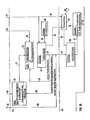
- the invention will first be explained in more detail with reference to the block diagram according to FIG. 1 consisting of parts 1A, 1B. This is divided into “processing levels” for a better overview.
- the level El has the function of an input level.
- Level E2.1, E2.2 of web-related processing follows, followed by level E3 of product-related processing.
- Machine-related processing takes place in the last level E4.
- the inputs required to carry out the method according to the invention are made in the input level.
- two input blocks “product planning 1" and “color requirement 5" and the catalog “system parameters 4" are provided as examples.
- Product Planning 1 at least current product information determining the respective scope of the printed product is stored.
- An example of “product planning” is shown in the form of an input mask in FIG. 14. It contains current information, in particular on the desired number of booklets, the maximum number of pages per booklet, the distribution of the page numbers of the printed matter among the individual Specify booklets and the desired format of the printed product, e.g. broadsheet or tabloid format.
- production type E ie individual production
- Another possible type of production is the so-called double production.
- typical web assignments can be combined into "production types".
- production type C is selected as an example.
- the further input block "color request" 5 in the input level E 1 serves to specify the at least the desired number of colors per page of the desired printed product.
- an example in the form of an input mask is shown in FIG.
- the necessary colors can be requested there, for example, for pages 1 to 16 of issue 1 and pages 17 to 22 of issue 2.
- a four-color print (4-F) for pages 1 and 16 and the additional colors blue (C) and red (M) for page 19 are provided. All other pages should be printed in black (SW). There is no special color (spot color) for any of the pages.
- the "Catalog: System parameters" 4 is also provided on the input level. All machine-dependent identifiers and data are usually stored in an unchangeable manner during system commissioning. From the multitude of plant parameters that are usually available, only a few are mentioned below as examples. For example, this includes the number of sections the respective printing press.
- FIG. 12 shows an example of a printing press consisting of the three sections S1, S2 and S3. Each section contains a folder F1, F2 or F3, each of which is assigned a certain number of printing units.
- the printing units D1 to D5 form the section S1 around the folder F1
- the printing units D6 to D10 around the folder F2 form the section S2
- the printing units D11 to 015 around the folder F3 form the section S3.
- the webs running through one or more of the printing units are fed to one of the folders for folding and cutting the printed product.
- Other important system parameters are the number of print units that can be used, the number of printing cylinders per printing unit and the number and width of paper webs that can be fed into the printing units from different roll carriers at the same time.
- Other important system parameters relate to influencing the possible web guides.
- the machine-dependent so-called quarter-cut options, the turning options and the partial web mixing options are also stored in the input block 4. This will be explained in more detail below.
- a "start path allocation” is determined. This is shown in FIG. 1 in the course-related processing level E2.2 in the form of the block 7 "Proposal: start course assignment (" MIBA ")". For this purpose, as shown by the arrows 6, 8, at least specifications from the blocks “product planning” 1 and “catalog: system parameters” 4 are required. According to an embodiment of the invention which is explained in more detail below, additional information about the arrow 9 from a “catalog: production types" 10 can be taken into account in order to form the "start path allocation".
- a "start path allocation" is used which uses the full width of the individual lanes required for the scope of the respective product. In doing so, product and machine-dependent influencing factors are largely taken into account. If, according to the further embodiment, "production types” are also present, production-dependent influencing variables can also be taken into account.
- the start path assignment found in the first step of the method according to the invention serves as the starting point for determining the “path guidance options” in the second step of the method.
- These are shown in FIG. 1A in block 18 as “lists: path guidance options” and are explained in more detail below with reference to FIG.
- the web guide options found are expanded by the existing color combinations. This is shown in FIG. 1B with block 22 as "list: color combinations per web guiding option".
- the possible color combinations are supplied to element 22 either as system parameters directly from catalog 4, or, in the presence of defined production types, from catalog 10 via paths 12, 15.
- a level E3 for "product-related processing" is already provided in FIG. 1B, in which the restructuring of the path guidance options from the list 18 from path-related to product-related is carried out in block 20.
- the path guidance options from the list 18 are thus not supplied to the list 22 directly, but rather indirectly via the paths 19, 21 for the purpose of the previous sorting in list 20.
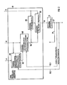
- FIG. 1B shows a selection of the path combinations of a path guidance option from the list 22. Only the web guidance possible with the color combination is permitted, which in comparison to the information in the input block 5 "color request" permits the production of a product with at least a matching or even greater color. Examples of possible product schemes are shown by way of example in FIGS. 16 and 17. With the information contained in the "Proposal: Product Scheme", it is already possible to say which page of which booklet with which page number on which web in which printing unit with which colors can be printed on the top and bottom. As a result, the desired assignment of the individual printing cylinders of the printing units involved to printing plates is already clearly determined. In principle, the result of the method according to the invention is available at output 27 of block 24 in FIG. 1B.
- one or more additional color combinations present in the list 22 can first be called up via the branch 28 in repetition of the fourth method step and the associated product schemes can be determined. If the color combinations contained in the list 22 are exhausted, the repetition of the third and fourth process steps can first be carried out via the branch 30 or 29, the next one in the list 18 or 20 included web guidance options can be activated in a web or product-related structure. With the help of this web guiding option, an associated list 22 "color combinations per web guiding options" is now created again. After this has been compared with the existing color requirement, further permissible product schemes can be called up.
- the method according to the invention thus has the particular advantage that further permissible printing plate assignments in the form of additional product scheme proposals 24 can be formed in a simple manner, without the entire method having to be repeated from the beginning. Rather, to generate further permissible product schemes, it is sufficient to repeat the third, or the third and fourth process step one or more times. It can be seen that under no circumstances does the entire process have to be carried out again from the beginning, since the start path assignment found in the first step continues to serve as the starting point for possible repetitions of the following process steps.
- the level E4 which is also present in FIG. 1B, for "machine-related processing" is particularly important if the possible color for the respective printed product through the respective product scheme proposal 24 exceeds the need stored in the color request 5 input block .
- the block 29 "color assignment" is supplied on the one hand with the color request from the input level via the connection 13 and, furthermore, with the current product pattern proposal 24 via the connection 34, which is actually possible due to the current printing plate assignment.
- the present color combination is restricted to the actual color requirement and / or the color requirement is expanded by utilizing the additional possibilities of the color combination.
- FIG. 1B The optimal printing plate assignment generated due to the reduction or expansion of the color requirement for the possible color of the present color combination is shown in FIG. 1B in the form of block 28 "Proposal: imposition scheme".
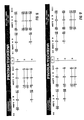
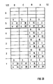
- Two possible imposition schemes are shown by way of example in FIGS. 19 to 22. It is now clearly and particularly clearly determined at which point of the 8 possible positions on the surface of a printing cylinder and on which printing cylinder in which printing unit which page of the current printed product is printed in which color. If, for example, the element in column D and line 5 is considered in FIG. 20, this relates to the fourth segment D of the fifth printing cylinder of printing unit 3. In this segment, page 21 of booklet 2 on one cylinder half and page 43 of booklet 4 on the second half of the cylinder in printed in color with the number 3.
- the "imposition schemes" shown in FIGS. 19 to 22 are explained in more detail below.
- block 32 "output: control printing press” is provided in FIG. 1B in level 4.
- all settings and switchovers are preferably made in the printing press in order to be able to produce the product defined in the "proposal product scheme” 24 or in the "proposal imposition scheme” 28.
- Output 32 sets the paper path associated with the respective printing plate assignment in the printing units and in the turning bar tower. Furthermore, the printing cylinders are covered with the appropriate printing plates at the intended locations and the corresponding colors are released for the desired color application.
- FIG. 3 a fictitious web assignment is first shown as an example. This was based on a product consisting of two booklets, each with 10 or 18 pages. Issue 1 should be printed on the right halves of the occupied webs, ie the machine drive side SI. Issue 2 should be printed on the left halves of the webs occupied, ie on the machine operating page SII. Furthermore, it is assumed that five webs of different widths are required to produce this printed product will. The example was chosen in such a way that there is an understandable insight into the path allocation options.
- lanes 1 and 2 are covered with full-width lanes, ie 4/4 lanes. These consist of two sheets on the machine sides SI and SII, each with a total of four pages. A total of eight pages can be printed on the front and back of a 4/4 web.
- the web 3 is covered, for example, with a 3/4 web, the web 4 with a 1/2 web (sheet) and the web 5 with a 1/4 web (partial sheet).
- the lanes that are not full, ie the 3/4, 1/2 and 1/4 lanes, are each shifted to the left on the machine operating side SII by way of example.
- each printing machine contains a slitter for each of the webs 1 to 5 to produce the sheets for the individual booklets.
- quarter cutters can also be provided on the left or right machine side SII or SI for producing quarter cuts in one or more webs.
- Such a quarter cutter can be used, for example, at the left end of the web 3 to produce the 1/4 web (partial sheet) marked with SW.
- so-called inlets exist between the individual webs, depending on the machine. In FIG. 3 it was assumed that such an inlet 1 to 5 is present after each of the webs 1 to 5. These can be used to carry out partial web turns or partial web mixes.
- FIG. 3 it was assumed that such an inlet 1 to 5 is present after each of the webs 1 to 5.
- the sheet marked with W on track 2 can be turned from the operator to the drive side with the aid of the inlet 2.
- the partial sheet marked SW can also be turned from the operator to the drive side with the aid of the inlet 3.
- BW sheet displacement of the left sheet of the web 1 with the aid of the inlet 4 and the partial web mixing device between the webs 4 and 5 within the booklet 2 is exemplary shown (BW sheet).
- this left-hand sheet from lane 1, indicated by a dashed arrow can be turned from the operator side to the drive side with simultaneous turning and mixing and moved into the inlet 3 (BW sheet)
- FIG. 2 shows the second step of expanding the start path assignment by the path guidance options in detail.
- the “lists: path guidance options” 18 are supplied with the start path allocation 7 via the connection 17.
- the path combinations available for the start path allocation are taken into account in a first sub-step.
- the block 181 "sublist: track combinations" is used for this purpose in FIG.
- the web combinations contain the combinations in the occupancy of the printing press with the webs of the start web occupancy, which are possible due to the maximum number of webs that can be occupied by the respective printing press.
- the path combinations can be formed in an order which is determined by a path priority list. This contains a machine-based or production-dependent order of precedence in the allocation of verifiable courses.
- path combinations when forming the path combinations, it can also be taken into account in which paths possibly necessary path cuts can be made depending on the machine.
- path cuts are in the foreground, since "quarter cut options" are not available on every path.
- Another sub-step can follow the formation of the path combinations in the second process step.
- the possible partial path combinations for a path combination are taken into account.
- This is shown in FIG. 2 by block 183 "sublist: partial web combinations". It deals the possible machine-dependent combinations in the distribution of the partial webs on the verifiable webs.
- the partial web combinations can be formed in the form of a web width sorting dependent on the web priority list.
- the partial web combinations are formed in a sequence, whereby at least in the first partial web combination, priority webs in the respective web combination are occupied with wide webs and subordinate webs with narrow webs. In the following partial web combinations, priority webs with narrow webs and subordinate webs with wide webs are increasingly used.
- At least the first partial path combination belonging to a path combination is determined with the aid of a path priority list and an additional partial path priority list.
- the lanes of the lane combination are initially assigned 4/4 lanes according to a ranking order specified by the lane priority list. Subsequently, the remaining lanes of the lane combination are occupied with partial lanes according to a ranking order specified by the partial lane priority list.
- a third sub-step can follow in a further embodiment.
- the existing turning options for a partial web combination are taken into account.
- the turning options can be formed in a sequence in which initially subordinate courses are subjected to the turns prescribed by the start course assignment. Only when there are further turning options are turns also provided on higher-ranking railways.
- the third sub-step taking into account the turning options for each sub-web combination, will be explained in more detail with reference to FIG. 7.
- a fourth and final sub-step can follow in the second step of extending the start web assignment by the web guidance options.
- This is shown in FIG. 2 with the block 187 "Sublist:” Bay Window Options ".
- These are the partial web mixing options which can be carried out per partial web combination by a so-called bay window device. These contain the interchanges that are machine-dependent for a partial web combination The mutual position of partial webs, in particular within a booklet. In a further embodiment, it can be taken into account to what extent it is possible, depending on the machine, to carry out these instead of individual turns using one of the partial web mixing options. This will be explained in more detail with the aid of FIG.
- FIG. 1B shows that further product scheme proposals can also be made by using the feedback 30 directly to access further path guidance options contained in the list 18 can be formed. If this list is now carried out in accordance with FIG. 2, the recourse 30 of FIG. 1B is advantageously divided into the two partial recurs 30.1 and 30.2 shown in FIG.
- FIG. 4 shows examples of possible start path assignments.
- Current product details are required as input variables for their formation, in particular about the scope of the respective printed product.
- the main input variables are the current number of issues and the number of pages per issue. As already explained, this information is preferably specified in block 1 "Product planning", FIG. 1A or an input mask in accordance with FIG. Further input variables can be found in the set of system parameters. In particular, this is the maximum possible number of webs that can be occupied by the respective printing press. If, according to a further embodiment, typical web assignments are combined to "production types", the number of the maximum webs that can be occupied in the respective production batch serves as the input variable for forming the starting web assignment. A desired production type can also be specified via the input mask "Product planning", FIG. 14. Depending on the embodiment, the formation of the start path assignment can be limited by further, in particular machine and production-dependent influencing variables. This is further explained in more detail using the examples shown in FIG. 4.
- FIGS. 4A, 4D and 4H exemplify three web assignments that are different due to the respective product scope.
- the covering of the verifiable webs with paper webs of the appropriate width was carried out solely from the point of view that the desired number of booklet pages are achieved.
- booklet 1 has 10 and booklet 2 has 14 pages.
- lanes 1 and 2 were initially covered with full-width lanes, and lanes 3 and 4 with a 3/4 and 1/4 lanes, respectively.
- a web-width-dependent pre-sorting has already been carried out when the web is shown in FIG. 4A. If, for example, wide webs are given priority over partial webs, the first webs are covered with full-width webs in accordance with FIG. 4A, while the remaining webs are covered with partial webs of decreasing width.
- web 1 can in this case have a full-width web which Lanes 2 and 3 with 3/4 lanes shifted to the right and left, respectively, and lane 4 with a 1/2 lane.
- the printed product only contains a booklet with 10 pages. Accordingly, lanes 1 to 3 are initially occupied with two 1/2 lanes shifted to the right and one shifted 1/4 lane.
- a web can also be saved here according to FIG. 4E.
- Web 1 is covered with a full width and web 2 with a 1/4 web. In this case, to correct the number of booklet pages, it is necessary to turn a 1/2 web from the left to the right machine page. This is identified in FIG. 4E by the marking W on lane 1. If a system constant prescribes that no roller carriers with 1/4 webs are available, the start web allocation can be formed according to FIG. 4F.
- Lanes 1 and 2 are each occupied with a 3/4 lane shifted to the right and a 1/2 lane. To correct the number of pages, it is necessary here to turn a 1/4 web created by a 1/4 cut and marked with SW from the left to the right machine side. If neither a 1/4 web from the roll carrier is available, nor is it possible to make a 1/4 cut, the start web allocation can be formed according to FIG. 4G. Here, lane 1 has a 3/4 lane shifted to the left and lane 2 has a 1/2 lane shifted to the right. To correct the number of booklets, it is necessary to turn a 1/2 web marked by W from the left to the right side of the machine.
- the printed product contains a booklet 1 with 14 and a booklet 2 with 6 pages.
- An associated, possible start lane assignment with a minimum number of lanes is shown in FIG. 4I.
- Lanes 1 and 2 are each covered with full-width lanes, and lane 3 with two 1/4 lanes. To correct the number of pages, here is one with W marked turn of a 1/2 lane from the left to the right machine side necessary.
- the start web assignment provides information about the number and width of webs required for the respective printed product, and, if necessary, cuts and turns necessary for correcting the number of pages. According to the examples in FIG. 4, information about the respective turning width and turning direction is therefore necessary to identify the individual turns. Since, as far as possible, no 3/4 partial webs are to be turned, the start web layout preferably contains information about the product-related turns of 1/2 and / or 1/4 webs between the two machine sides. There is also information on the number of quarter cuts required.
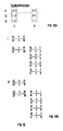
- FIG. 5A shows an example of the possible lane combinations for the case in which the underlying start lane occupancy requests the occupancy of two lanes, but a maximum of three lanes can be occupied are. This number can correspond to the maximum number of webs that can be occupied by the respective printing press. If, according to a further embodiment, typical web assignments in the form of production types are combined into basic quantities, the maximum number of documentable webs permitted for the selected production type is used to form the web combinations.
- the assignable lanes are assigned in order. For example, the first combination of trains provides for occupancy of lanes 1 and 2, the second for occupancy of lanes 1 and 3, and the third combination of lanes for occupancy of lanes 2 and 3.
- the path combinations are formed in an order which is determined by a path priority list.
- a path priority list Such a case is shown as an example in FIG. 5B.
- Ranks 1, 3, 2 are assigned to assignable courses 1, 2, 3 according to the list of course priorities.
- the first lane combination thus provides for lanes 1 and 3, the second combination lanes 1 and 2, and the third combination lanes 2 and 3.
- a comparison of FIGS. 5A and 5B shows that the same track combinations are formed overall, but in a different order.
- the ranking of trains is influenced in particular by machine and production-dependent sizes. These are, for example, the color of a web and the distance of the web outlet from the printing unit from the associated fold. For example, a web whose runout is closer to the folder than that of other webs can be given a higher rank in the web priority list. This ensures that this web, which has the advantage of a short web guiding path of the folder, is primarily occupied with a web from the start web allocation when forming the web combinations. Only subordinate train combinations no longer use this advantage, because here too the Assignment of lower-order webs of the printing press with webs requested by the start web assignment is provided. Furthermore, the color can also influence the rank of webs.
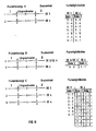
- FIG. 13 shows such web priority lists for a printing press with a maximum of three assignable webs.
- five production types A to E are defined, whereby production types A, B allow the occupancy of a maximum of two webs, and C to E a maximum of all three existing webs.
- the rankings in the layout of the tracks are specified differently. Is e.g. If production type A is selected and the respective start assignment requests the assignment of a single path, two path combinations are possible. In the first, priority combination, lane 2 is occupied, in the second, subordinate combination, lane 1 is occupied. If, on the other hand, production type B is selected, a maximum of two lanes is started with one lane with lane 1, while the subordinate combination provides for lane 2.
- the occupancy of the three permissible lanes for production types C to E. is made.
- the number of resulting lane combinations depends on the number of lanes requested by the start lane allocation, while their order is determined by the respective lane priority list.
- the path combinations can additionally take into account the paths in which cuts requested by the start path allocation can be carried out depending on the machine.
- the focus here is in particular on the quarter cut options that are usually not available on all lanes. It is assumed in FIG. 5C that the start path allocation requires the occupation of two paths and the execution of a 1/4 cut S. In technical terms, 1/4 cuts can only be carried out on lanes 2 and 3.
- the web combination 3 expands into two sub-combinations 3.1 and 3.2, since the 1/4 cut S can be carried out on web 2 or 3 when the webs 2 and 3 are occupied.
- the combinations 1 and 2 in FIGS. 5B and 5C are identical, since only one of the webs 2 and 3 is occupied, and therefore the 1/4 cut S must be made on one of these webs.
- the possible partial web combinations can be taken into account in the second step of expanding the start web allocation by the web guiding options furthermore to one of the web combinations found.
- the partial web combinations possible for an element of the "sublist: web combinations" 181 are formed and are preferably stored in a further sublist 183. This is a web width sorting, which is further explained with reference to FIG 6.
- FIG. 6A the path combinations associated with a start path assignment are shown as an example. It was assumed that of the maximum of four lanes that could be occupied, three were to be occupied with a 4/4, 3/4, and 1/4 lane due to the requirement of the start lane allocation. The individual path combinations were formed in an order determined by a path priority list. Each of the partial web combinations can now be used to generate further web guidance options be subjected to a further, deeper processing step.
- FIG. 6 shows an example of the web combination 2, for which possible partial web combinations were formed according to different strategies in FIGS. 6B, 6C, 6D. These influence the order in which the partial lane combinations are formed within a group. Each of these groups thus contains the same combinations, albeit arranged in a different order.
- the partial lane combinations are formed in a 4/4, 3/4, 1/4 lanes sequence which is exclusively dependent on the width of the involved and requested by the start lane occupancy. It can be seen that in combination 2.1, the courses are occupied with increasingly narrower courses in decreasing order. Thus, lane 1 is covered with a 4/4 lane, lane 2 with a 3/4 lane and lane 3 with a 1/4 lane. In the following partial lane combinations, this hierarchy is shifted in favor of narrower lanes, i.e. at the expense of wider railways. For example, in the sub-lane combination 2.2 the 3/4 and 1/4 lanes changed their positions.
- FIG. 6C shows another possibility for the formation of partial web combinations.
- At least the first partial web combination 2.1 of the web combination 2 is determined with the aid of a web priority list and an additional partial web priority list.
- assignable lanes with the aid of the lane priority list, first use the full-width webs started.
- lane 2 with the highest lane priority 1 is initially occupied with the 4/4 lane.
- the remaining lanes 1 and 3 are now occupied with partial lanes with the aid of the partial lane priority list. Since lane 4 cannot be occupied in lane combination 2, lane 3, which has the lower sub-lane priority 2, is initially occupied with the next wider 3/4 lane.
- the formation of the web assignments according to the examples in FIGS. 6C and 6D has the particular advantage that, by influencing the sequence of the individual sub-web combinations, machine and production-dependent influencing variables in the form of differently assignable rail priority and partial rail priority lists are taken into account.
- the wish can be taken into account that in many cases the full-width webs should be covered according to different criteria than the partial webs. This may be due to the fact that the pages of a printed product with the greatest color should be printed on full-width webs as far as possible, whereas the pages with the least color should be printed on narrower webs.
- boundary conditions can be taken into account in a particularly simple manner with the aid of the ranking sequences which can be predetermined differently depending on the web width, based on the web and partial web priority lists according to the invention. For example, webs which print units with a large number of printing cylinders pass through can be preferred depending on the machine and production by assigning a correspondingly high priority in the web priority list. Furthermore, additional boundary conditions can be taken into account by assigning ranks in the partial railway priority list. Due to the more difficult guidance of partial webs, there is often a desire to guide them through the printing units in the shortest possible way. This can be taken into account in particular in that the webs which cross the printing units involved faster and whose path between the outlet of the respective printing unit and the associated folder are shorter are preferred by assigning a higher rank in the partial web priority list.
- each of the partial web combinations is subjected to a further, third partial processing step.
- the turning options available for a partial web combination from sublist 183 are taken into account, and preferably in a subsequent one Sublist 185 stored. These are the machine-dependent turns of partial webs between the drive and operating sides of the printing press for the respective partial web combination. This is further explained using the example of FIG 7.
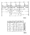
- the partial web combination according to FIG. 7A which serves as an example as a starting point, is based on a product that consists of two booklets, each with 12 or 4 pages. It is assumed that the start lane assignment specifies the occupancy of two lanes with 4/4 lanes and requests the turning of a 1/2 lane from the left to the right machine side in order to correct the number of pages. Furthermore, it is assumed that, depending on the machine, such turns are possible on each of the two occupied tracks. As a result, the two turning options shown in FIGS. 7B and 7C result. According to an advantageous embodiment of the invention, the turning options available for a partial web combination are formed in a sequence in which first subordinate webs and then priority webs are subjected to the requested turns. The turn option shown in FIG. 7B is thus formed first, since the requested 1/2-turn turn is carried out on the subordinate track 2 there. In the subsequent turning possibility according to FIG. 7C, the 1/2-lane turn is finally provided on the higher-ranking lane 1.
- the second exemplary partial web combination is based on a product which consists of two booklets, each with six pages. It is assumed that the underlying start lane allocation prescribes the allocation of two lanes, each with a 4/4 lane and a 1/2 lane. To correct the number of pages in this example, it is necessary to turn a 1/4 web from one side of the machine to the other.
- FIGS. 7F on the other hand, the turn only takes place from the extreme left position on lane 2 to the left half of the machine drive side SI. Accordingly, in FIGS. 7G and 7H, the 1/4 web is turned from the right half on the machine operating side SII into one of the two positions on the machine driving side SI. If the 1/2-lane is on the right-hand side of lane 2 in FIG. 7D, there are four further turning options. These differ from those shown in FIGS. 7E to 7H by opposite arrow directions.
- the turning options available for a partial web combination can also be formed here in a sequence that is particularly dependent on the machine and production.
- the turns are initially provided for railways, which experience has shown that plant engineering can be used without major problems.
- turns are also provided for tracks that may be more difficult to control in terms of system technology.
- Subordinated lanes in the partial lane combination are preferred to be subjected to the requested turns. This is due to the fact that such webs are usually occupied with partial webs, in particular 1/4 lanes. Such tracks are easier to turn than, for example, a 3/4 track.
- the existing sub-web blending options can be taken into account in the second step of the method according to the invention for adding a sub-web combination, in addition to the start web assignment by all web guiding options.
- These are also known as "Bay Window” options (BW).
- BW Back Window
- These are the machine-specific exchanges in the mutual position of partial webs, particularly within a booklet, for the respective partial web combination. This is also explained in more detail with reference to FIG 8.
- FIG. 8 is based on a printed product which consists of two booklets, each with 16 or 8 pages.
- the associated start lane allocation provides for the allocation of three lanes with 4/4 wide lanes.
- To correct the respective number of booklet pages it is necessary to turn a 1/2 web from the machine operator to the machine drive side.
- FIGS. 8A and 8B are based on the assumption that this 1/2-lane turn is made on lane 3.
- the figures also show an example of some machine-dependent partial web mixtures. For example, in FIG. 8A, the sheets of issue 1 are swapped over for the original path order 1, 2, 3 into 2, 1, 3.
- the right sheet of web 1 is reinserted from web 1 by a corresponding adjustment of the printing press and as a so-called BW sheet between the sheets of webs 2 and 3.
- FIG. 8A by means of a solid arrow.
- FIG. 8B shows the further mixing possibility, with the one on lane 1 Sheet from Issue 1 led out and reintroduced in Issue 1 following the sheet on lane 3.
- the means of partial web mixing it is known that it is possible to effect different color distributions within a printed product.
- the pages on lane 1 in FIG. 8 are printed in four colors, while the remaining pages on lanes 2 and 3 are only printed in black and white, e.g. in FIG. 8A the multi-colored sheet of web 1 is laid in the middle of booklet 1 or at the end of booklet 2.
- FIG. 8A the sheet from lane 1, booklet 1, when it is introduced as a BW sheet, can be "reversed" between lanes 2 and 3 at the same time. The front and back are swapped.
- FIG. 8C shows the case in which the sheet on lane 1, booklet 2 is turned both on the machine drive side and is inserted as a BW sheet between lanes 2 and 3. Accordingly, the same 1/2 web is introduced in FIG. 8D with simultaneous turning and mixing on the machine drive side following web 3 as a BW web.
- FIG. 8E shows the case where a turn is carried out by means of the devices for partial web mixing without additional mixing.
- the sheet marked W is introduced on lane 1, issue 2 as a BW sheet between lane 1 and lane 2 of issue 1. This corresponds to a turn of the sheet from the machine operating side to the drive side.
- FIG. 9A shows an example of a path guidance, for example from sublist 187 of FIG. 2, as a starting point. It concerns a product of two booklets, each with 16 or 8 pages.
- the turn W of a 1/2 web, ie a so-called turning sheet, required for correcting the number of booklets, is provided on web 3.
- the sheet on lane 1 is provided as a BW sheet for introduction following lane 2.
- the path guidance option of FIG. 9A is in a path-related structure, since all the desired turns and mixtures are only specified at their starting points and apparently have not yet been carried out.
- lane 1 consists of an arc on the left and an arc intended for mixing on the right.
- web 3 consists of a sheet W on the machine operating side which is intended for turning onto the machine drive side.
- the future location of these arches, and thus the future structure of each booklet can thus be recognized completely, but only indirectly from the path-related structure of the path guiding option of FIG. 9A.
- FIG. 9B shows the same path guidance option after re-sorting into product-related structure. It can be seen that the right half of lane 1 is no longer occupied, and issue 1 on lane 2 begins with an unchanged "straight arch”. In volume 1 there follows a "BW-Einlaufbogen-Bahn 1" brought up from lane 1, which in turn is followed on lane 3 by an unchanged "straight arch”. Booklet 1 is finally closed by a "turning sheet” turned over from the machine operating side. Correspondingly, issue 2 begins or ends with an unchanged "straight-ahead sheet" on web 1 or 2.
- FIG. 9B the front or back of the first straight-ahead sheet from booklet 1 is provided for pages 1, 16 and 2, 15, respectively.
- Booklet 1 consists, as desired, of 16 pages with the numbers 1 to 16, and Book 2 of 8 pages with the numbers 17 to 24.
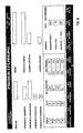
- FIG. 10A first shows an example of an extract from printing machine or. Permissible color combinations depending on the production type.
- the color combination web 1 which is designated by I
- a maximum of three colors can be printed on both sides, and the webs 2, 3 can be printed on the front or back with a maximum of one or two colors.
- the color combinations shown by way of example in FIG. 10A have identical color sums. So the sum of the maximum possible colors for the front and back of all webs results in the number 12. This is due to the fact that the printing units involved in the manufacture of the product and passed through by the three webs have a maximum, fixed number of Have pressure cylinders. This also limits the maximum possible value of the color sum, ie the maximum color that can be applied to the front and back of all webs. This will be explained in more detail using the example of the "production types" in FIGS. 11 and 12.
- FIG. 10B shows the product-related web guiding possibility of FIG. 9B, expanded by the color combinations I, II of FIG. 10A.
- I the sheets in booklet 2 and 1, originating from lane 1 and for the front and back pages of the sheets provided for product pages 17, 18, 23, 24 and 3, 4, 13, 14, can each have a maximum three colors can be printed. All other sheets in issues 1 and 2, which resulted from lanes 2 and 3, can be printed in one color on the front and in a maximum of two colors on the back.
- FIG. 10B II the sheets provided for pages 17, 18, 23, 24 and 3, 4, 13, 14 in booklet 2 and 1 on the front and back, respectively, each with a maximum of four or two colors be printed.
- the pages provided for pages 19, 20, 21, 22 and 1, 2, 15, 16 in Issue 2 and 1, respectively can be 3: 1 on the front with a maximum of three and on the according to the possible color combination for web 2 Color can be printed on the back.
- the last two sheets in booklet 1, which are intended for pages 5, 6, 11, 12 and 7, 8, 9, 10, respectively, can be changed due to the previous processing on lane 3 on front and Back side can only be printed with one color.
- At least one of the web guide options shown by way of example in FIG. 10B and expanded by the existing color combinations is now used to determine the desired printing plate occupancy. In comparison to the information in the input mask 5 "color request", this must allow a greater or at least the same color for each product page. If one of the web guiding options fulfills this condition, it is used to form the product scheme 24, FIG. 1B.
- partial sheets are arranged within a booklet in such a way that they come to rest in the middle of the booklet after it has been folded.
- the partial sheets are arranged after the last position of the layer of sheets forming a booklet. If, for example, a partial sheet were present in FIG. 9B in booklet 1, this would be located after the turning sheet provided for pages 7, 8, 9, 10. It can also happen that existing partial sheets should not be in the middle of the respective booklet. In such a case, a partial sheet is placed between the stacks of sheets forming a booklet.
- frequently occurring, typical train assignments can be combined into "basic quantities".
- production types are preferably oriented to the scope, color and color distribution of frequently occurring products.
- certain parameters are deliberately limited a product-dependent limitation of the possible paper guides by a printing machine, and thus the possible printing plate assignments.
- the definition and the selection of a defined production type precede the first method step of determining the start web allocation.
- a preselection is made, depending on the product, from the maximum number of webs that can be occupied by the respective printing press.
- a product-dependent restriction is made in the maximum color of the front and back of the individual sheets. This indirectly also limits the possible paper paths through the printing press.
- FIG. 11 three possible production types A, B, C and the associated color options are shown by way of example using a printing machine consisting of two printing units DE3, DE4.
- production type A a maximum of two webs can be occupied, each of which runs separately through one of the printing units DE3, DE4.
- This type of production thus enables both webs to be printed on the front and back with approximately the same, relatively large color. This is symbolized by the value 3 for the average number of colors on the top and bottom of each lane.
- the color options associated with this web guiding option are also shown in a table. So can both web 1 and web 2 can be printed with all combinations between the values 5: 1 and 1: 5 of the color from front to back.
- the color options of both webs can be freely combined with one another.
- each color option for lane 1 can be freely combined with a common color combination of lanes 2 and 3.
- FIG. 12 shows an example of the assignment of production types A to H to the printing units D1 to D15 of a printing press.
- the production types A to F can be produced on each of the sections S1 to S3, since only the printing units are involved within the respective section, for example the printing units D1 to D5 in section S1.
- the printing units of one section, but also at least one printing unit of one or two adjacent sections, are involved in the core. This is due to the larger scope and greater color of the products assigned to these types of production. It can be seen from FIG.
- FIG. 14 shows that in addition to the current scope of the respective product, in particular represented in the number of booklets and the pages per booklet, production type C and production type E were also selected.
- production type C In the case of production type E called “individual production”, each of the four segments of a printing cylinder is covered with a different printing plate on the two printing areas, each comprising approximately half the cylinder circumference. For this reason, it is easily possible in this case to produce a printed product consisting of four booklets.
- both 180 ° areas of each cylinder segment are covered with identical pressure plates. In this case, usually only one printed product consisting of two booklets can be produced.
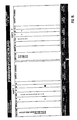
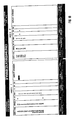
- FIG. 16 shows a first possible result of the method according to the invention which belongs to FIGS. 14 and 15. Due to the selected production type and the current scope of the product, three webs are required for its production, which are shown in the middle of the "Product scheme" mask by the numbers 1, 2, 3 lying one above the other.
- the booklets 1, 2 shown to the left of this dividing line are preferably each produced by the printing plates lying on a circumferential half of all printing cylinder segments, while the booklets 3, 4 shown to the right of the dividing line are generated by the printing plates arranged on the opposite circumferential halves of each printing cylinder segment.
- the product-oriented, internal structure of booklets 1, 2 and 3, 4 in FIG. 16 corresponds in principle to the illustration in FIGS. 9B and 10B.
- the second sheet in issues 1 and 3 each consists of a "straight sheet" on sheet 2, which can be printed in one color on the front and back.
- the arches adjoining each of them, provided for the sides 5, 6, 11, 12 or 27, 28, 33, 34, are turning arches brought up from the other side of the machine. These have the same color as the previous sheets, as they were also produced on lane 2 before the turn was carried out.
- FIG. 16 also shows that in the middle of the booklets 2 and 4 a quarter sheet is provided for the product pages 19, 20 and 41, 42, respectively, which are each produced on the web 3 with the maximum colors 3: 1.
- FIG. 17 shows a further possible printing plate assignment in the form of the associated product scheme. According to a further embodiment of the invention, this results either from Repetition of the fourth or at least partial repetition of the third and fourth process step.
- a comparison with FIG. 16 shows that the partial sheets bearing the pages 19, 20 and 41, 42 in the middle of the booklets 2 and 4 are now each produced on web 2.
- the partial sheets produced on web 2 pages 19, 20 and 41, 42
- sheets pages 3, 4, 13, 14 and 25, 26, 35, 36
- have more color options This means that the front of the partial webs involved can be printed with a maximum of three colors instead of just one. Nevertheless, both product schemes in FIGS.
- FIGS. 16, 17 meet the minimum color requirement for the color of the individual pages, which is specified in the input mask, FIG. Another difference between the two product schemes can be seen, for example, in the fact that the last sheets bearing pages 7, 8, 9, 10 and 29, 30, 31, 32 in booklets 1 and 3 are now designed as turning sheets. These are produced together with the sheets in front of them on lane 3 in the same color and then turned from the left to the right side of the machine. Different, permissible partial web combinations, turning options and color combinations have thus contributed in particular to the formation of the product schemes of FIGS. 16, 17.
- the product diagrams of FIGS. 16 and 17 can contain a color on some pages that exceeds the color requirement of FIG. In such a case, it is advantageous if, with the aid of a further "color assignment" mask, FIG. 18, an adaptation between the information in the "color request” mask, FIG. 15, to that in the product schemes, Figures 16, 17 contained options is made. This adjustment can take the form of a reduction in the actual color possibilities and / or an expansion of the color requirement. According to a particularly advantageous, further embodiment of the invention, the "imposition schemes" shown in FIGS. 19 to 22 are formed after this adaptation.
- the imposition scheme in FIG. 19, 20 belongs to the product scheme of FIG. 16, and the imposition scheme in FIG. 21, 22 belongs to the product scheme FIG. 17.
- the imposition schemes in principle do not contain any information that goes beyond the content of the associated product schemes, they nevertheless enable easier handling of the now optimal printing plate assignments generated with the aid of the method according to the invention.
- it is very easy to see immediately at which point of a printing cylinder in a printing unit which booklet page and in which color is advantageously to be produced.
- FIGS. 19, 20 and 21, 22 directly reproduce the exact assignment of the respective printing cylinders of printing units 3 and 4, respectively.
- 20 all four segments A to D of the printing cylinders 1 and 5 of the printing unit 3 are completely covered with printing plates.
- the printing cylinders 5, 6 of the printing unit 4 are complete, i.e. all four segments A to D, covered with pressure plates.
- the printing cylinders 1 and 4 only the segments A, B, C, and in the printing cylinders 2, 3 only the segment C are each occupied with printing plates.
- page 1 in booklet 1 and page 23 in booklet 3 are each produced in four-color printing.
- these two pages are on the first or the second circumferential half on segment A of the printing cylinders 1 to 4 produced.
- segment A pages 1, 23 on cylinder 1 with the color of the identifier 3, then on cylinder 2 in the color with the identifier 12, then on cylinder 3 in the color with the identifier 15 and finally on cylinder 4 in the color with the identifier 9 printed.
- the settings associated with the imposition schemes in FIGS. 19 and 21 are made in the printing machine in terms of control technology. This includes in particular the setting of the paper path belonging to the found printing plate occupancy within the individual printing unit, the activation of the necessary turning, partial web mixing and cutting devices, the activation of the ink application devices for the individual printing cylinder segments and the allocation with the corresponding printing plates.
- a program-controlled computer is preferably used to carry out the method according to the invention.
- so-called “automation systems” for real-time management of technical processes, i.e. for observation, control and regulation are particularly suitable for this.
Landscapes
- Inking, Control Or Cleaning Of Printing Machines (AREA)
Applications Claiming Priority (2)
| Application Number | Priority Date | Filing Date | Title |
|---|---|---|---|
| DE3939673 | 1989-11-30 | ||
| DE3939673A DE3939673A1 (de) | 1989-11-30 | 1989-11-30 | Verfahren und vorrichtung zur bestimmung der druckplattenbelegung auf den druckzylindern der druckeinheiten einer druckmaschine |
Publications (3)
| Publication Number | Publication Date |
|---|---|
| EP0430261A2 true EP0430261A2 (fr) | 1991-06-05 |
| EP0430261A3 EP0430261A3 (en) | 1991-09-11 |
| EP0430261B1 EP0430261B1 (fr) | 1994-02-09 |
Family
ID=6394538
Family Applications (1)
| Application Number | Title | Priority Date | Filing Date |
|---|---|---|---|
| EP90122893A Expired - Lifetime EP0430261B1 (fr) | 1989-11-30 | 1990-11-29 | Procédé pour déterminer la disposition de plaques d'impression sur les cylindres des éléments d'impression d'une machine à imprimer |
Country Status (2)
| Country | Link |
|---|---|
| EP (1) | EP0430261B1 (fr) |
| DE (2) | DE3939673A1 (fr) |
Cited By (2)
| Publication number | Priority date | Publication date | Assignee | Title |
|---|---|---|---|---|
| DE4330242A1 (de) * | 1993-09-07 | 1995-03-09 | Hell Ag Linotype | Verfahren und Einrichtung zur elektronischen Montage von Druckbogen |
| DE4401901A1 (de) * | 1994-01-24 | 1995-07-27 | Heidelberger Druckmasch Ag | Verfahren zur Kontrolle des Ausschießschemas von Druckformen |
Families Citing this family (3)
| Publication number | Priority date | Publication date | Assignee | Title |
|---|---|---|---|---|
| DE4328026A1 (de) * | 1993-08-20 | 1995-03-09 | Roland Man Druckmasch | Kommunikationsverfahren und -system zum computerunterstützten Drucken |
| AU2002360905A1 (en) | 2001-12-21 | 2003-07-15 | Koenig And Bauer Aktiengesellschaft | Simulation system for a printing machine |
| DE10163261A1 (de) * | 2001-12-21 | 2003-07-17 | Koenig & Bauer Ag | Simulationssystem für eine Druckmaschine |
Family Cites Families (5)
| Publication number | Priority date | Publication date | Assignee | Title |
|---|---|---|---|---|
| FR1527907A (fr) * | 1967-03-20 | 1968-06-07 | Etudes De Machines Speciales | Dispositif de mise à jour automatique d'un cylindre d'impression d'une imprimeuse rotative |
| GB2008493B (en) * | 1977-09-17 | 1982-02-24 | Timsons Ltd | Book making |
| DE2754941A1 (de) * | 1977-12-09 | 1979-06-13 | Harris Corp | Verfahren und vorrichtung zur einstellung einer druckmaschine |
| US4495582A (en) * | 1982-06-04 | 1985-01-22 | Harris Graphics Corporation | Control system for pre-setting and operation of a printing press and collator |
| US4984773A (en) * | 1987-10-06 | 1991-01-15 | Rockwell International Corporation | Method of and apparatus for composing a press imposition |
-
1989
- 1989-11-30 DE DE3939673A patent/DE3939673A1/de not_active Withdrawn
-
1990
- 1990-11-29 DE DE90122893T patent/DE59004552D1/de not_active Expired - Fee Related
- 1990-11-29 EP EP90122893A patent/EP0430261B1/fr not_active Expired - Lifetime
Cited By (3)
| Publication number | Priority date | Publication date | Assignee | Title |
|---|---|---|---|---|
| DE4330242A1 (de) * | 1993-09-07 | 1995-03-09 | Hell Ag Linotype | Verfahren und Einrichtung zur elektronischen Montage von Druckbogen |
| US5809218A (en) * | 1993-09-07 | 1998-09-15 | Linotyoe-Hell Ag | Method for the electronic assembly of printer's forms |
| DE4401901A1 (de) * | 1994-01-24 | 1995-07-27 | Heidelberger Druckmasch Ag | Verfahren zur Kontrolle des Ausschießschemas von Druckformen |
Also Published As
| Publication number | Publication date |
|---|---|
| DE3939673A1 (de) | 1991-06-06 |
| DE59004552D1 (de) | 1994-03-24 |
| EP0430261A3 (en) | 1991-09-11 |
| EP0430261B1 (fr) | 1994-02-09 |
Similar Documents
| Publication | Publication Date | Title |
|---|---|---|
| EP0529552A1 (fr) | Dispositif de guidage de bande dans une machine à imprimer rotative pour bandes | |
| EP1634833B1 (fr) | Machine à imprimer comprenant au moins un groupe d'impression. | |
| EP0888887A2 (fr) | Configuration en forme de tour de barres de retournement | |
| EP2159683B1 (fr) | Procédé et dispositif pour répartir une tâche d'impression selon les caractéristiques des produits d'impression | |
| DE102006020054A1 (de) | Rollenrotationsdruckmaschine | |
| DE102005053652A1 (de) | Druckmaschine und Verfahren zum Herstellen von Zeitungen | |
| EP1867479B1 (fr) | Machine d'impression rotative dotée d'une unité d'impression contenant un cylindre d'unité d'impression et procédé de production d'un produit d'impression | |
| EP0430261B1 (fr) | Procédé pour déterminer la disposition de plaques d'impression sur les cylindres des éléments d'impression d'une machine à imprimer | |
| WO2003004272A1 (fr) | Machine a imprimer comportant plusieurs sections | |
| DE10163209A1 (de) | Vorrichtung zur Herstellung von Falzprodukten | |
| DE102007023312B4 (de) | Rollenrotationsdruckmaschine und ein Verfahren zur Erzeugung eines Druckproduktes | |
| DE102005031010A1 (de) | Produkt einer bahnverarbeitenden Maschinen sowie Vorrichtungen zur Herstellung des Produktes | |
| DE102005036451B4 (de) | Vorrichtung zur Erzeugung eines Produktabschnittes in einer bahnverarbeitenden Maschine | |
| DE102008044251A1 (de) | Falztrichteranordnung | |
| DE10311636B4 (de) | Wendeturm | |
| DE102007000928B4 (de) | Rotationsdruckmaschine | |
| DE10307202B4 (de) | Verfahren zur Voreinstellung von Produktionen einer Rollenrotationsdruckmaschine | |
| EP1593509A2 (fr) | Machine d'impression avec au moins une unité d'impression | |
| WO2006111522A1 (fr) | Installation de machines a imprimer | |
| DE102015111286B4 (de) | Druckmaschine | |
| DE102005016749B3 (de) | Verfahren zur Bestimmung eines Ausschießschemas | |
| DE10158483B4 (de) | Bogen zur Erstellung eines Buchblocks, Verfahren zur Erstellung eines Buchblocks mit solchen Bogen und Druckplatte zum Bedrucken eines solchen Bogens | |
| EP3299168A2 (fr) | Procédé de fabrication d'un produit imprimé | |
| DE102006058196A1 (de) | Druckmaschinenanlage |
Legal Events
| Date | Code | Title | Description |
|---|---|---|---|
| PUAI | Public reference made under article 153(3) epc to a published international application that has entered the european phase |
Free format text: ORIGINAL CODE: 0009012 |
|
| 17P | Request for examination filed |
Effective date: 19901220 |
|
| AK | Designated contracting states |
Kind code of ref document: A2 Designated state(s): CH DE FR GB IT LI SE |
|
| PUAL | Search report despatched |
Free format text: ORIGINAL CODE: 0009013 |
|
| AK | Designated contracting states |
Kind code of ref document: A3 Designated state(s): CH DE FR GB IT LI SE |
|
| 17Q | First examination report despatched |
Effective date: 19930521 |
|
| GRAA | (expected) grant |
Free format text: ORIGINAL CODE: 0009210 |
|
| AK | Designated contracting states |
Kind code of ref document: B1 Designated state(s): CH DE FR GB IT LI SE |
|
| REF | Corresponds to: |
Ref document number: 59004552 Country of ref document: DE Date of ref document: 19940324 |
|
| ITF | It: translation for a ep patent filed | ||
| GBT | Gb: translation of ep patent filed (gb section 77(6)(a)/1977) |
Effective date: 19940513 |
|
| ET | Fr: translation filed | ||
| PGFP | Annual fee paid to national office [announced via postgrant information from national office to epo] |
Ref country code: GB Payment date: 19941018 Year of fee payment: 5 |
|
| PGFP | Annual fee paid to national office [announced via postgrant information from national office to epo] |
Ref country code: SE Payment date: 19941116 Year of fee payment: 5 |
|
| PGFP | Annual fee paid to national office [announced via postgrant information from national office to epo] |
Ref country code: FR Payment date: 19941117 Year of fee payment: 5 |
|
| PLBE | No opposition filed within time limit |
Free format text: ORIGINAL CODE: 0009261 |
|
| STAA | Information on the status of an ep patent application or granted ep patent |
Free format text: STATUS: NO OPPOSITION FILED WITHIN TIME LIMIT |
|
| PGFP | Annual fee paid to national office [announced via postgrant information from national office to epo] |
Ref country code: DE Payment date: 19950119 Year of fee payment: 5 |
|
| EAL | Se: european patent in force in sweden |
Ref document number: 90122893.2 |
|
| 26N | No opposition filed | ||
| PGFP | Annual fee paid to national office [announced via postgrant information from national office to epo] |
Ref country code: CH Payment date: 19950216 Year of fee payment: 5 |
|
| PG25 | Lapsed in a contracting state [announced via postgrant information from national office to epo] |
Ref country code: GB Effective date: 19951129 |
|
| PG25 | Lapsed in a contracting state [announced via postgrant information from national office to epo] |
Ref country code: SE Effective date: 19951130 Ref country code: LI Effective date: 19951130 Ref country code: CH Effective date: 19951130 |
|
| REG | Reference to a national code |
Ref country code: CH Ref legal event code: PL |
|
| GBPC | Gb: european patent ceased through non-payment of renewal fee |
Effective date: 19951129 |
|
| PG25 | Lapsed in a contracting state [announced via postgrant information from national office to epo] |
Ref country code: FR Effective date: 19960731 |
|
| PG25 | Lapsed in a contracting state [announced via postgrant information from national office to epo] |
Ref country code: DE Effective date: 19960801 |
|
| EUG | Se: european patent has lapsed |
Ref document number: 90122893.2 |
|
| REG | Reference to a national code |
Ref country code: FR Ref legal event code: ST |
|
| PG25 | Lapsed in a contracting state [announced via postgrant information from national office to epo] |
Ref country code: IT Free format text: LAPSE BECAUSE OF NON-PAYMENT OF DUE FEES Effective date: 20051129 |