EP0430573A2 - Palier à billes à dÀ©placement linéaire - Google Patents
Palier à billes à dÀ©placement linéaire Download PDFInfo
- Publication number
- EP0430573A2 EP0430573A2 EP90312687A EP90312687A EP0430573A2 EP 0430573 A2 EP0430573 A2 EP 0430573A2 EP 90312687 A EP90312687 A EP 90312687A EP 90312687 A EP90312687 A EP 90312687A EP 0430573 A2 EP0430573 A2 EP 0430573A2
- Authority
- EP
- European Patent Office
- Prior art keywords
- ball
- loaded
- duct
- land
- balls
- Prior art date
- Legal status (The legal status is an assumption and is not a legal conclusion. Google has not performed a legal analysis and makes no representation as to the accuracy of the status listed.)
- Granted
Links
Images




Classifications
-
- F—MECHANICAL ENGINEERING; LIGHTING; HEATING; WEAPONS; BLASTING
- F16—ENGINEERING ELEMENTS AND UNITS; GENERAL MEASURES FOR PRODUCING AND MAINTAINING EFFECTIVE FUNCTIONING OF MACHINES OR INSTALLATIONS; THERMAL INSULATION IN GENERAL
- F16C—SHAFTS; FLEXIBLE SHAFTS; ELEMENTS OR CRANKSHAFT MECHANISMS; ROTARY BODIES OTHER THAN GEARING ELEMENTS; BEARINGS
- F16C29/00—Bearings for parts moving only linearly
- F16C29/04—Ball or roller bearings
- F16C29/06—Ball or roller bearings in which the rolling bodies circulate partly without carrying load
- F16C29/068—Ball or roller bearings in which the rolling bodies circulate partly without carrying load with the bearing body fully encircling the guide rail or track
- F16C29/0683—Ball or roller bearings in which the rolling bodies circulate partly without carrying load with the bearing body fully encircling the guide rail or track the bearing body encircles a rail or rod of circular cross-section, i.e. the linear bearing is not suited to transmit torque
- F16C29/0685—Ball or roller bearings in which the rolling bodies circulate partly without carrying load with the bearing body fully encircling the guide rail or track the bearing body encircles a rail or rod of circular cross-section, i.e. the linear bearing is not suited to transmit torque with balls
- F16C29/0688—Ball or roller bearings in which the rolling bodies circulate partly without carrying load with the bearing body fully encircling the guide rail or track the bearing body encircles a rail or rod of circular cross-section, i.e. the linear bearing is not suited to transmit torque with balls whereby a sleeve surrounds the circulating balls and thicker part of the sleeve form the load bearing tracks
Definitions
- the present invention relates to linear motion ball bearings.
- the ball bearings contemplated are of the type which are generally utilized to support a member, as for example, a carriage or pillow block on a shaft while providing linear motion to the supported member.
- the present invention is directed to improvements in linear motion ball bearings.
- the improvement is specifically directed to a linear motion ball bearing of the type which facilitates supporting a member such as a carriage or pillow block on a support member such as an elongated shaft while facilitating slidable movement of the pillow block along the shaft.
- Bearings of the type contemplated by the present invention generally include an outer housing and an inner cage which defines ball loops for containing bearing balls.
- the ball loops include open portions which facilitate load transfer between the outer housing of the bearing and a supporting shaft while permitting the load balls to leave the load ball areas and return to unloaded ball areas.
- such bearings have been structured to provide linear motion but have not been constructed in a manner which facilitates uniform distribution of loading, uniform wear, quiet and smooth operation and overall bearing performance. Attempts have been made to improve bearing performance; however, to date, although such attempts have been somewhat successful they are not believed to have raised bearing performance to the desired levels.
- a linear motion ball bearing for providing relative linear motion in combination with a shaft, which comprises housing means having an axially elongated opening therethrough, an axially elongated generally tubular shaped ball retaining means positioned within the housing means opening and defining a plurality of endless ball loops therein extending generally in the axial direction of the ball retainer.
- the retaining means has an inner surface and an outer surface radially displaced from one another.
- the ball loops are spaced circumferentially apart about the ball retaining means.
- Each loop contains a plurality of balls with each loop having a first ball duct for a row of loaded balls and a second ball duct for a row of unloaded balls.
- Each first ball duct is open through the inner and outer surfaces of the ball retaining means, and each ball loop is arranged with the first ball duct next adjacent the first ball duct in the adjacent ball loop along one axially extending side and the second ball duct therein is adjacent the second ball duct in the next adjacent ball loop along the other axially extending side.
- the housing defines a land opposite each pair of adjacent first ball ducts and extends inwardly, each land extending sufficiently inward and being of sufficient circumferential dimension to support the loaded balls of adjacent pairs of first ball ducts and having a contoured relatively smooth surface for accommodating the loaded balls positioned within the corresponding opposed pair of respective first ball ducts of respectively adjacent ball loops.
- each contoured relatively smooth surface has an arcuate configuration.
- land for supporting loaded balls is dimensioned and configured such that balls in adjacent loaded ball ducts become unloaded upon movement away from each first ball duct and toward the second ball duct of the respective ball loop.
- each ball support land is formed integral with the housing and the housing contains an outer wall portion and an inner wall portion spaced radially inward of the outer wall portion.
- the ball support land is configured to define an arcuate central portion to support loaded balls and ramp portions extending from the arcuate portion towards the wall portion of the housing at least at each axial end portion.
- the ball support land is preferably of a length generally greater than the width.
- the arcuate loaded ball surface extends from the inner surface of the outer housing and defines ramped surfaces extending axially at least along the length of each land.
- Each ramp portion adjacent the width portion of each land extends in a transverse direction and from the ball support surface toward the inner surface portion of the housing and forms a generally acute angle with the inner surface portion of the housing.
- the loaded ball duct defines a loaded ball zone approximately equal in length to the corresponding open portion extending from the radially inner to radially outer surface of the ball retaining means.
- the interface between each the loaded ball surface portion of each land and the adjacent transverse ramp portion corresponds generally with the end of the loaded ball zone.
- the cross-section of each ball duct is generally semi-circular and is related to the diameter of each ball.
- the ball retaining means is in the form of a cage having ramped surfaces configured for engagement with each axially extending ramp adjacent the longer side of each land so as to fix the circumferential position of the cage within the outer housing.
- each unloaded ball duct which is defined by the dimension between the base of the unloaded ball duct and the corresponding opposed inner surface of the outer housing.
- the height of this duct is preferably continuously maintained at a substantially fixed dimension slightly greater than the diameter of each ball between the end limit locations of each loaded ball zone.
- Each ball loop is comprised of two opposed elongated straight ball ducts connected at each end by arcuate ball paths, and each loaded and unloaded ball duct extends over an axial dimension approximately equal to the straight elongated axial portion of each ball loop.
- each ball duct portion beyond the open portion of the loaded ball duct is contoured such that each ball first rises to a level radially outward of the loaded ball land surface beyond the end portions of each loaded ball duct.
- the ball cage is fabricated of a polymeric material, i.e. synthetic plastic such as nylon, acetal, polyacetal, polycarbonates, polyamides, etc.
- the linear motion ball bearing for providing relative linear motion in combination with a shaft comprises a housing having an axially elongated opening therethrough, an axially elongated generally tubular shaped ball retainer positioned within the housing opening and defining a plurality of endless ball loops therein extending generally in the axial direction of the ball retainer, the ball retainer inner surface and an outer surface radially displaced from one another, the ball loops spaced circumferentially apart about the ball retainer and each containing a plurality of balls.
- Each loop has a first generally axially extending ball duct for a row of loaded balls and a second generally axially extending ball duct for a row of unloaded balls.
- Each first ball duct is open through the inner and outer surfaces of the ball retainer, and each ball loop is arranged with the first ball duct next adjacent the first ball duct in the adjacent ball loop along one axially extending side and the second ball duct therein adjacent the second ball duct in the next adjacent ball loop along the other axially extending side.
- the housing defines a land opposite each pair of adjacent first ball ducts extending inwardly and integral therewith, each land extending sufficiently inwardly and being of sufficient circumferential dimension to support the loaded balls of adjacent pairs of first ball ducts and having a contoured relatively smooth surface for accommodating loaded balls positioned within the corresponding opposed pair of respective first ball ducts of respectively adjacent ball loops.
- Each relatively smooth ball support surface is connected to the inner surface portion of the outer housing by a ramped surface on at least two end portions to thereby accommodate and support ball movement between the loaded and unloaded ball ducts.
- the loaded and unloaded ball ducts are connected by an arcuate ball duct having a ball support surface comprising an arcuate ball path, the ball path being defined by an arcuate ball support surface comprising at least three continuous curved surfaces which support the balls such that the center of the ball approximately defines a locus comprised of three correspondingly continuous curves approximately as follows:
- the diameter of the first control cylinder is approximately 1 1/2 ball diameters and the central axis extends through the intersection between each side ramp and the inner surface of the sleeve.
- the location of the central axis of this cylinder may vary depending upon the ball location and the ball diameter; however in no event can the surface of the cylinder distal from the ball be located inward of the intersection between each side ramp and the inner surface of the sleeve. Also, if the ball support land is flat, the chord will be coincident with the land.
- the ball travel centerline which defines the locus of the center of the arcuate portion of the cross-section of the arcuate ball duct is comprised of at least three correspondingly continuous curves.
- the ball support surface is the surface generated by a non-rotating ball travelling such that the locus of the center follows the specifically defined curves.
- the actual surface must be slightly larger to accommodate rolling motion of the ball.
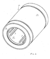
- FIG. 1 there is illustrated a perspective view of the linear motion ball bearing 10 constructed according to the invention.
- the bearing includes outer housing 12 which is elongated and tubular in configuration.
- a ball retainer -- or cage -- 14 is positioned within the housing and defines a plurality of endless ball loops spaced about the circumference thereof and extends axially of the housing.
- the ball retainer contains a suitable plurality of bearing balls 11 which are unloaded and balls 13 which are loaded.
- the balls are identical to each other except that a ball is unloaded when it is positioned in an unloaded ball duct and it is loaded when it is positioned in a loaded ball duct.
- pairs of adjacent ball loops are generally evenly distributed about the ball retainer.
- FIG. 1 An exemplary cage retainer 16 is shown in Fig. 1 in schematic form.
- An identical retainer (not shown) is positioned on the opposite side of the bushing bearing.
- the cage retainers are welded on the inner side (not shown), as by ultrasonic welding techniques, to the ball cage on each side of the cage.
- the retainers are preferably constructed of a material ultrasonically compatible with the material of the cage.
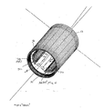
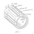
- the outer housing 12 is best illustrated in Fig. 4 and the ball cage 14 is best illustrated in Fig. 5.
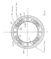
- the combined outer housing 12 and ball cage 14 are best illustrated in Figs. 1 and 3.
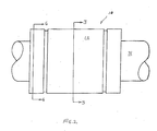
- Fig. 2 is a plan view of the outer housing.
- the outer housing 12 is preferably constructed of a suitable bearing material such as bearing steel. Alternatively, such suitable materials as stainless steel, ceramics, etc., may be used.
- the ball cage 14 is preferably constructed of a material having sufficient strength to retain the balls in their loaded and unloaded positions and to provide ball ducts which are sufficiently smooth to permit relatively free and unimpeded movement of the balls between the loaded and the unloaded ball ducts.
- a polymeric material is preferred. Synthetic plastics such as nylon, acetal, polyacetal, polycarbonates or polyamides in general, may be used and are in fact preferred. Other suitable materials will be known to persons skilled in the art.
- the ball retainer 14 includes a plurality of endless ball loops 16 extending axially of the cage.
- Each loop 16 contains a loaded ball duct 18 and an adjacent unloaded ball duct 20 connected by respective arcuate loops 22 and 24 which define an arcuate ball path having a three part "floor".
- the cage is defined by an outer surface 26 and an inner surface 28 of circular cross-section spaced radially inward of the outer surface 26.
- the outer surface is somewhat irregular and discontinuous, i.e. it includes the surface of each land between loaded and unloaded ball ducts.
- Each loaded ball duct is open through the radial inner surface by axial slot 30 to permit balls positioned therein to engage a working shaft 31, shown in Fig. 2, and the respective inner loaded ball surface of the outer housing 12 as will be described in further detail hereinbelow.
- the outer housing 12 contains lands 32 which extend inwardly from housing inner surface 44, and are positioned opposite each ball loop when the ball retainer 14 is positioned within the housing.
- Each land 32 contains an arcuate centrally positioned elongated loaded ball surface 42 which is polished for contact with the balls and which supports the loaded balls when positioned in the opposed respective loaded ball duct.
- Each land is surrounded on all sides by a ramped surface designated as 36 on the axially extending sides and 38 on the transverse sides as shown in Fig. 4.
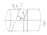
- the ramped surfaces form a generally acute angle " " with the inner circular surface 28 of the outer housing 12 as shown in Fig. 6.
- the end ramps which extend transversely of the housing are dimensioned and oriented to accommodate ball transfer between the loaded ball duct of a ball loop and the unloaded ball duct of the same loop.
- the balls in the loaded ball duct of adjacent loops are in engagement with a particular bearing support surface of the respective land and travel between the loaded and the unloaded ball ducts via the arcuate end loops of each ball loop as noted.
- the transversely extending ramped surfaces 38 at each end of a land 32 accommodate ball travel between the ducts.
- the ramped surfaces which extend axially of the cage serve to key the cage in a circumferentially fixed position by providing oppositely disposed ramped surfaces 36 on each side of each land 32 which engage with correspondingly dimensioned and opposed ramped surfaces 40 formed by ball retainer 14.
- each elongated slot 30 in retainer 14 is dimensioned to terminate at a location which approximately corresponds to the interface between the transverse ramped surface 38 and the polished arcuate surface 42.
- the precisely defined contour of the ball path in the radial loops 22, 24, as will be described hereinbelow, permit each ball to enter the corresponding radial end loop 22, 24 and to travel therein with a minimum of vibration and chatter.
- the surface which connects each loaded and unloaded ball duct is a relatively complex curved surface formed in the ball cage so as to accommodate rolling transfer of balls between the ducts.
- the precise curved surface is dimensioned and configured to maintain a relatively constant "ceiling to floor" height above and below each ball as it travels between the loaded, ball duct and the unloaded ball duct.
- the "ceiling" above the ball between the loaded and unloaded ball paths is defined by the transversely extending ramp 38 at each end of axial land 32 and the inner surface 44 of housing 12 as shown in Fig. 4.
- the surface required to carry the ball between the loaded and unloaded ball ducts is best defined as three separate and individual curved surfaces which form a continuous arcuate curved "floor" for the balls which vary in "height” so as to continuously maintain the distance between the "floor” and the “ceiling” (i.e. the transverse ramp 38 and housing inner surface 44) substantially constant.
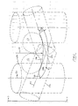
- the three-part arcuate surface forming a ball path between the loaded and unloaded ball ducts is best described with reference to Figs. 6-8 by defining the ball travel centerline which is the locus of the center of the ball when travelling within the semi-circular portion of the cross section of the arcuate ball duct which is comprised of three substantially continuous curves.
- the curves there which define the locus of the ball center will be described in terms of the intersection of certain geometric surfaces which will be referred to herein as "hypothetical" or "imaginary" control surfaces.
- Such surfaces are geometric surfaces in space which define the requisite curves by their intersections with each other.
- the dimensions of these surfaces are specified as a function of the dimensions of the components of the bearing as will be seen in the description which follows, i.e. the balls, the housing dimensions, etc.
- Fig. 6 is an enlarged schematic cross-sectional view taken along lines 6-6 of Fig. 2 illustrating a typical land 32 which extends radially inward from inner surface 44 of housing 12.
- the transverse conical ramped surface 38 extends from the arcuate surface 42 of land 38 and intersects the surface 44 of housing 12 as shown at 46. Since the imaginary control surfaces on each side of the land are identical, reference will be made to the control surfaces on one side in connection with the drawings.
- a primary imaginary control cylinder 48 is shown in stippled lines and extends as shown with respect to the land 32 and has its center line 50 preferably extending through the intersection between the axial ramp 36 and the inner surface 44 of housing 12.
- the imaginary control cylinder is of a diameter approximately one and one half (i.e. 1 1/2) ball diameters and extends parallel to a radius line 51 as shown which extends to the mid point of the land 32.
- a second imaginary control cylinder 52 is also shown in stippled lines and extends in a generally orthogonal direction with respect to the center axis of the housing and has its central axis 54 tangent to the arcuate working surface 42 of the land 32 at the loaded ball path as shown, i.e. the point of contact between the ball and the land. In fact the point of tangency is located at the land end, i.e. where the arcuate land meets the transverse conical ramp 38.
- This cylinder 52 is approximately one ball diameter as shown.
- orthogonal I refer to the relationship of the respective axes whereby they are generally normal to each other, but do not necessarily intersect.
- a first portion of the "floor" of the ball path between the loaded and unloaded ball ducts is characterized as the "ball pick-up region" and is defined as the floor portion of the surface generated by the ball when travelling such that the locus of the ball center coincides with the curve defined by the intersection of primary control cylinder 48 and second control cylinder 52.
- the second portion of the "floor" of the ball path extending aft of the "ball pick-up" region in a direction away from the loaded ball duct is defined by the surface generated by the ball when travelling such that the locus of the ball center coincides with the curve defined by the intersection between the following two imaginary control surfaces which are illustrated in Fig. 7.
- the first control surface is the primary imaginary - or hypothetical - control cylinder 48 shown in Fig. 6 and described above in connection with the initial ball pick-up region.
- the view of imaginary control cylinder 48 shown in Fig. 7 is a side view taken along lines 7-7 of Fig. 6.
- the third imaginary control surface is a surface shown in stippled lines in Fig. 7 at 58 and is a conical surface which is "concentric” and “parallel” to the conical ramp surface 38 but removed “orthogonally” outward from the ramp surface 38 by dimension 60 equal to approximately 1/2 the ball diameter.
- the second portion of the floor of the ball path between the loaded and unloaded ball ducts is defined as the floor portion of the surface generated by the ball when travelling such that the locus of the ball center coincides with the curve defined by the intersection between primary imaginary control cylinder 48 and third imaginary conical surface 58.
- the third section of the floor of the ball path between the loaded and unloaded ball ducts is defined by the intersection between the imaginary control surfaces shown in Fig. 8 which will now be described.
- FIG. 8 there is illustrated an enlarged schematic "cross-sectional" view similar to Fig. 6, illustrating the same imaginary control cylinders 48 shown in Fig. 6.
- a fourth imaginary control surface 62 is shown which is circular and concentric with the circular inner surface 44 of the outer housing 12, but spaced inwardly of surface 44 by dimension 64 equal to 1/2 ball diameter.
- the third and final portion of the complex "floor" or surface between the loaded and unloaded ball ducts is thus defined as the floor portion of the surface generated by the ball when travelling such that the locus of the ball center coincides with the curve defined by the intersection between primary imaginary control cylinder 48 and imaginary circular control surface 62 shown in Fig. 8.
- the three part surface which supports the balls between the loaded and unloaded ball ducts has been defined.
- portions of each of the three above defined surfaces are selected so as to define a continuous ball path or "floor". It has been found that the resulting surface maintains substantially constant, the "floor to ceiling” height surrounding each ball between the point where the ball exits the loaded portion of the loaded ball duct and returns to the unloaded ball duct.
- the substantially constant height has been found to be ideally adapted for the balls to minimize chatter and vibration in the movement between the ducts.
- the surface defining the floor is "ideally” generated by a ball when its center travels along the specific curves defined. However, as a practical matter the actual surface of the floor is generated with sufficient clearance to permit the balls to travel in rolling fashion therethrough.
- the floor to ceiling height remains substantially constant, where the ceiling is defined as the transverse ramp 38 of land 32 and the inner surface 44 of housing 12.
- the dimensions of these critical surfaces may be increased or reduced proportionately, within a predetermined permissible range; however, the total variation should not exceed about 10 percent.
- a dimension is specified as 1/2 ball diameter or greater, variations below 1/2 ball diameter are not permissible since ball movement would be prevented in such event.
- the dimension of 1 1/2 ball diameters is specified to provide an appropriate turning radius for the balls. Greater variations of the dimension of this control cylinder are therefore permissible provided that the diameter of the primary control cylinder is greater than the diameter of the ball. In each instance, the diameter selected will determine the turn radius of the ball path between the ducts.
- the preferred diameter specified, i.e. 1 1/2 ball diameters, has been found to provide an appropriate turning radius. However, any diameter greater than 1 ball diameter may be utilized for this primary hypothetical control cylinder.
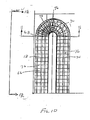
- Figs. 9-14 there is shown a series of selective representations of the relatively complex ball paths between the loaded and unloaded ball ducts.
- the actual envelopes of these ball paths are shown by a series of arcuate lines which represent the progressive movement of the ball within the loaded and unloaded ducts and between these ducts.
- a schematic cross-sectional view of the loaded and unloaded ball paths is shown illustrating the radially open portion 66 of the loaded ball duct 18.
- the initial surface defined as the ball pick-up region is shown at 68.
- the second portion of the complex "floor" of the ball is shown at 70, and the third complex curved portion of the floor is shown at 72.
- the loaded ball zone is shown at 66 and the unloaded ball duct "floor" is shown at 74.
- Fig. 11 there is shown a view of a ball path between a loaded ball duct and an unloaded ball duct illustrating the ball envelope extending from loaded ball path 66 to ball lift 68, ball ramp 70, and ball path 72 to unloaded ball path 74.
- Fig. 12 is a side view illustrating the ball envelope and the loaded path 66 and the unloaded path 74.
- Fig. 13 illustrates a perspective view of the envelope of a typical ball path between the loaded ball path 66 and the unloaded path 74.
- Fig. 14 is a view similar to Fig. 9 illustrating the ball envelope in the ball pick-up region 68.
- Fig. 15 is a cross-sectional view taken along lines 15-15 of Fig.
- Fig. 14 illustrating a ball in the loaded ball path 66 shown in Fig. 9 and a ball in the unloaded ball path 74 shown in Fig. 9.
- the darkened region 66 is an end view of the ball pick-up region 68 shown in Fig. 9.
- Fig. 16 is a view of a portion of the cross-sectional view of Fig. 3, greatly enlarged, illustrating the ball and the ball profile envelope in adjacent pairs of loaded ball paths 66 and unloaded ball paths 74.
- the relative radial ball positions are shown with the unloaded ball position in the unloaded duct being radially outward of the radial ball position in the loaded duct 18.
- Still another benefit resulting from the present invention is obtained in connection with the actual molding process for producing the the ball retainer 28 shown in Fig. 5.
- This advantage is illustrated in Fig. 17 in which exemplary mold sections 78 are illustrated for molding of a plastic material in ball retainer 14.
- the provision of adjacent loaded ball ducts 18 surrounded by unloaded ball ducts 20 facilitate the use of four identical mold sections 78 as shown in Fig. 18 with mold portions 18′ and 20′ configured and dimensioned to mold the appropriate ducts.
- prior arrangements which utilized alternating loaded and unloaded ball ducts it was necessary to utilize more than four mold sections. In many instances for an eight track bearing, for example, eight or more sections were needed to accommodate the repeating pattern.
- the present invention thus simplifies the cage molding process of the ball retainer.
- the outer housing necessarily contained multiple ball support lands equal to the quantity of ball tracks. Now, with four lands to support eight tracks, broching of the housing to form the lands has been simplified.
Landscapes
- Engineering & Computer Science (AREA)
- General Engineering & Computer Science (AREA)
- Mechanical Engineering (AREA)
- Bearings For Parts Moving Linearly (AREA)
Applications Claiming Priority (2)
| Application Number | Priority Date | Filing Date | Title |
|---|---|---|---|
| US07/440,973 US5046862A (en) | 1989-11-22 | 1989-11-22 | Linear motion ball bearing |
| US440973 | 1989-11-22 |
Publications (3)
| Publication Number | Publication Date |
|---|---|
| EP0430573A2 true EP0430573A2 (fr) | 1991-06-05 |
| EP0430573A3 EP0430573A3 (en) | 1992-04-22 |
| EP0430573B1 EP0430573B1 (fr) | 1996-04-17 |
Family
ID=23750971
Family Applications (1)
| Application Number | Title | Priority Date | Filing Date |
|---|---|---|---|
| EP90312687A Expired - Lifetime EP0430573B1 (fr) | 1989-11-22 | 1990-11-21 | Palier à billes à déplacement linéaire |
Country Status (7)
| Country | Link |
|---|---|
| US (1) | US5046862A (fr) |
| EP (1) | EP0430573B1 (fr) |
| JP (1) | JPH03186610A (fr) |
| BR (1) | BR9005914A (fr) |
| CA (1) | CA2030018C (fr) |
| DE (1) | DE69026577T2 (fr) |
| MX (1) | MX170266B (fr) |
Cited By (1)
| Publication number | Priority date | Publication date | Assignee | Title |
|---|---|---|---|---|
| RU2626432C1 (ru) * | 2016-05-16 | 2017-07-27 | Федеральное государственное бюджетное образовательное учреждение высшего образования "Саратовский государственный технический университет имени Гагарина Ю.А." (СГТУ имени Гагарина Ю.А.) | Шариковая втулка |
Families Citing this family (24)
| Publication number | Priority date | Publication date | Assignee | Title |
|---|---|---|---|---|
| US5138862A (en) * | 1991-08-27 | 1992-08-18 | Ball Corporation | Ram guidance system |
| US5221145A (en) * | 1992-01-17 | 1993-06-22 | Rmb Roulements Miniatures | Linear bearing |
| US5346313A (en) | 1993-07-20 | 1994-09-13 | Thomson Industries, Inc. | Linear motion bearing assembly |
| US5558442A (en) * | 1993-07-20 | 1996-09-24 | Thomson Industries, Inc. | Linear motion bearing assembly |
| US5669716A (en) * | 1995-03-14 | 1997-09-23 | Hiwin Technologies Corporation | Linear ball bearing |
| US5613780A (en) * | 1995-06-29 | 1997-03-25 | Thomson Industries, Inc. | Linear motion bearing assembly |
| US5829882A (en) * | 1996-11-14 | 1998-11-03 | Thomson Ind Inc | Linear motion bearing assembly |
| RU2132007C1 (ru) * | 1997-08-22 | 1999-06-20 | Акционерное общество "АвтоВАЗ" | Подшипник линейный |
| AU1092000A (en) | 1998-10-27 | 2000-05-15 | Thomson Industries Inc. | Nested track bearing |
| JP4794865B2 (ja) * | 2005-02-04 | 2011-10-19 | 株式会社リコー | 画像形成装置 |
| JP5229604B2 (ja) | 2007-01-12 | 2013-07-03 | 株式会社リコー | 画像形成装置 |
| EP2037329B1 (fr) | 2007-09-13 | 2014-07-02 | Ricoh Company, Ltd. | Unité de courroie d'appareil de formation d'images et procédé de contrôle de l'entraînement de la courroie |
| JP5234412B2 (ja) | 2008-04-08 | 2013-07-10 | 株式会社リコー | ベルト駆動装置及び画像形成装置 |
| JP5288247B2 (ja) | 2008-06-24 | 2013-09-11 | 株式会社リコー | 画像形成装置及び画像形成方法 |
| JP2010112516A (ja) * | 2008-11-10 | 2010-05-20 | Jtekt Corp | ボールスプライン |
| EP2278410B1 (fr) | 2009-07-14 | 2015-10-07 | Ricoh Company, Ltd. | Appareil de formation d'images capable de réduire l'expansion et la contraction des images |
| US9689426B2 (en) | 2010-07-15 | 2017-06-27 | Thomson Industries Inc. | Linear motion bearing with modular bearing segments |
| CN105587767A (zh) | 2010-07-15 | 2016-05-18 | 托马森工业(有限)公司 | 直线运动轴承组件 |
| BR112013001040A2 (pt) * | 2010-07-15 | 2016-05-24 | Thomson Ind Inc | mancal linear com trilhas de mancal aninhadas |
| EP2598763A1 (fr) * | 2010-07-28 | 2013-06-05 | Thomson Industries, Inc. | Système de palier pour mouvement linéaire avec barre à autoréglage |
| CN103742532B (zh) * | 2013-12-31 | 2016-08-17 | 广州市昊志机电股份有限公司 | 一种滚珠花键副 |
| US9091301B2 (en) * | 2014-01-02 | 2015-07-28 | Hiwin Technologies Corp. | Deflecting device for ball spline device |
| JP6580347B2 (ja) * | 2015-03-04 | 2019-09-25 | 日本トムソン株式会社 | リニアブッシング |
| CN110469582B (zh) * | 2019-08-20 | 2020-11-03 | 南京工程学院 | 一种组合式的自散热自润滑直线轴承 |
Family Cites Families (23)
| Publication number | Priority date | Publication date | Assignee | Title |
|---|---|---|---|---|
| DE7345379U (de) * | 1975-06-26 | Skf Kugellagerfab Gmbh | Kugelbüchse | |
| US2576269A (en) * | 1946-01-30 | 1951-11-27 | John B Thomson | Ball bearing |
| US2503009A (en) * | 1946-06-07 | 1950-04-04 | John B Thomson | Ball bearing for linear motion |
| US2509749A (en) * | 1946-06-07 | 1950-05-30 | John B Thomson | Ball bearing for linear motion |
| US2628135A (en) * | 1949-03-15 | 1953-02-10 | Thomson John B | Antifriction bearing for linear motion |
| DE1257495B (de) * | 1961-02-16 | 1967-12-28 | Star Kugelhalter Gmbh Dt | Kugelbuechse |
| US3190703A (en) * | 1962-06-25 | 1965-06-22 | Thomson | Bearing structure |
| BE790112A (fr) * | 1971-10-18 | 1973-02-01 | Heim Universal Corp | Ensemble de roulement a billes |
| US3844629A (en) * | 1972-08-15 | 1974-10-29 | Ransome Hoffmann Pollard | Linear motion ball bearings |
| DE2363033B2 (de) * | 1973-12-19 | 1977-10-27 | Skf Kugellagerfabriken Gmbh, 8720 Schweinfurt | Kugelbuechse mit zweireihigen laufbahntraegern |
| CH583383A5 (fr) * | 1973-12-21 | 1976-12-31 | Skf Ind Trading & Dev | |
| US4005913A (en) * | 1975-01-08 | 1977-02-01 | Thomson Industries, Inc. | Linear motion bearing block |
| DE2557351C3 (de) * | 1975-12-19 | 1982-09-23 | Skf Kugellagerfabriken Gmbh, 8720 Schweinfurt | Kugelbüchse |
| US4206951A (en) * | 1976-04-02 | 1980-06-10 | Skf Kugellagerfabriken Gmbh | Linear rolling bearing |
| IT1123952B (it) * | 1978-01-27 | 1986-05-07 | Star Kugelhalter Gmbh Dt | Manicotto a sfere per guide longitudianli a sfere e metodo per la sua fabbricazione |
| DE2830400C2 (de) * | 1978-07-11 | 1982-11-25 | Skf Kugellagerfabriken Gmbh, 8720 Schweinfurt | Kugellager zur längsbeweglichen Lagerung von Maschinenteilen |
| CH631244A5 (fr) * | 1979-02-26 | 1982-07-30 | Schmid Roost J Sro Kugellagerw | Element de guidage a billes axial-rotatif. |
| JPS55135226A (en) * | 1979-04-06 | 1980-10-21 | Minoru Suda | Direct-acting ball bearing |
| DE3326601A1 (de) * | 1983-07-23 | 1985-02-07 | Skf Kugellagerfabriken Gmbh | Kugellager fuer laengsbewegungen |
| US4541674A (en) * | 1984-02-24 | 1985-09-17 | William Mitschang | Linear motion roller bearing |
| DE3512013A1 (de) * | 1985-04-02 | 1986-10-02 | Skf Linearsysteme Gmbh | Kugellager fuer laengsbewegungen |
| JPH0715287B2 (ja) * | 1986-08-19 | 1995-02-22 | 日本トムソン株式会社 | 無限直線運動用ころ軸受 |
| EP0402493A1 (fr) * | 1989-06-13 | 1990-12-19 | V M E I "Lenin" | Palier linéaire |
-
1989
- 1989-11-22 US US07/440,973 patent/US5046862A/en not_active Expired - Lifetime
-
1990
- 1990-11-15 CA CA002030018A patent/CA2030018C/fr not_active Expired - Lifetime
- 1990-11-21 EP EP90312687A patent/EP0430573B1/fr not_active Expired - Lifetime
- 1990-11-21 MX MX023413A patent/MX170266B/es unknown
- 1990-11-21 DE DE69026577T patent/DE69026577T2/de not_active Expired - Fee Related
- 1990-11-22 BR BR909005914A patent/BR9005914A/pt not_active IP Right Cessation
- 1990-11-22 JP JP2315704A patent/JPH03186610A/ja active Pending
Cited By (1)
| Publication number | Priority date | Publication date | Assignee | Title |
|---|---|---|---|---|
| RU2626432C1 (ru) * | 2016-05-16 | 2017-07-27 | Федеральное государственное бюджетное образовательное учреждение высшего образования "Саратовский государственный технический университет имени Гагарина Ю.А." (СГТУ имени Гагарина Ю.А.) | Шариковая втулка |
Also Published As
| Publication number | Publication date |
|---|---|
| BR9005914A (pt) | 1991-09-24 |
| JPH03186610A (ja) | 1991-08-14 |
| CA2030018C (fr) | 1993-08-10 |
| DE69026577D1 (de) | 1996-05-23 |
| EP0430573B1 (fr) | 1996-04-17 |
| EP0430573A3 (en) | 1992-04-22 |
| CA2030018A1 (fr) | 1991-05-23 |
| MX170266B (es) | 1993-08-12 |
| US5046862A (en) | 1991-09-10 |
| DE69026577T2 (de) | 1996-12-19 |
Similar Documents
| Publication | Publication Date | Title |
|---|---|---|
| EP0430573B1 (fr) | Palier à billes à déplacement linéaire | |
| US5413416A (en) | Roller guide member for full complement roller bearing | |
| US5328277A (en) | Cage for roller bearings | |
| US6155718A (en) | Slide guide and its roller chain with ends | |
| EP0649990A1 (fr) | Palier à rouleaux entièrement complémentaire à autoréglage | |
| US4138167A (en) | Rolling bearing including lengthwise convex race rails | |
| KR890002294B1 (ko) | 직선운동 로울러 베어링 | |
| US6855080B2 (en) | Chain | |
| US6113274A (en) | Linear guideway having spacers and spacer ball | |
| US4896974A (en) | Spherical spacer of a crossed roller bearing assembly | |
| JPS58137616A (ja) | 無限摺動用ボ−ルスプライン軸受 | |
| EP0926368B1 (fr) | Roulement pour vitesses de rotation élevées | |
| EP0449595A2 (fr) | Palier linéaire | |
| GB2223543A (en) | Linear rolling bearing | |
| US4294100A (en) | Method of manufacturing a seamless outer sleeve for a ball bearing | |
| CN100427764C (zh) | 分离器和使用该分离器的线性导引件以及线性运动装置 | |
| GB2067494A (en) | Endless conveyors | |
| US4934841A (en) | Polymer cage for radial bearing | |
| GB2279415A (en) | A rolling bearing | |
| US4239299A (en) | Ball bearing for linear motion | |
| US3899221A (en) | Thrust bearings | |
| GB2181791A (en) | Endless ball spline | |
| US4572591A (en) | Ball bearing arrangement for longitudinal movement on a shaft or the like | |
| GB2174153A (en) | Recirculating linear ball bearings | |
| ES296683U (es) | Rodamientos de bolas lineal para la conduccion de un objeto sobre un arbol cilindrico. |
Legal Events
| Date | Code | Title | Description |
|---|---|---|---|
| PUAI | Public reference made under article 153(3) epc to a published international application that has entered the european phase |
Free format text: ORIGINAL CODE: 0009012 |
|
| AK | Designated contracting states |
Kind code of ref document: A2 Designated state(s): DE FR GB IT |
|
| PUAL | Search report despatched |
Free format text: ORIGINAL CODE: 0009013 |
|
| AK | Designated contracting states |
Kind code of ref document: A3 Designated state(s): DE FR GB IT |
|
| 17P | Request for examination filed |
Effective date: 19920619 |
|
| 17Q | First examination report despatched |
Effective date: 19931005 |
|
| GRAH | Despatch of communication of intention to grant a patent |
Free format text: ORIGINAL CODE: EPIDOS IGRA |
|
| GRAA | (expected) grant |
Free format text: ORIGINAL CODE: 0009210 |
|
| AK | Designated contracting states |
Kind code of ref document: B1 Designated state(s): DE FR GB IT |
|
| REF | Corresponds to: |
Ref document number: 69026577 Country of ref document: DE Date of ref document: 19960523 |
|
| ITF | It: translation for a ep patent filed | ||
| ET | Fr: translation filed | ||
| PLBE | No opposition filed within time limit |
Free format text: ORIGINAL CODE: 0009261 |
|
| 26N | No opposition filed | ||
| REG | Reference to a national code |
Ref country code: GB Ref legal event code: IF02 |
|
| PGFP | Annual fee paid to national office [announced via postgrant information from national office to epo] |
Ref country code: DE Payment date: 20081114 Year of fee payment: 19 |
|
| PGFP | Annual fee paid to national office [announced via postgrant information from national office to epo] |
Ref country code: IT Payment date: 20081126 Year of fee payment: 19 |
|
| PGFP | Annual fee paid to national office [announced via postgrant information from national office to epo] |
Ref country code: FR Payment date: 20081112 Year of fee payment: 19 |
|
| PGFP | Annual fee paid to national office [announced via postgrant information from national office to epo] |
Ref country code: GB Payment date: 20081119 Year of fee payment: 19 |
|
| GBPC | Gb: european patent ceased through non-payment of renewal fee |
Effective date: 20091121 |
|
| REG | Reference to a national code |
Ref country code: FR Ref legal event code: ST Effective date: 20100730 |
|
| PG25 | Lapsed in a contracting state [announced via postgrant information from national office to epo] |
Ref country code: FR Free format text: LAPSE BECAUSE OF NON-PAYMENT OF DUE FEES Effective date: 20091130 |
|
| PG25 | Lapsed in a contracting state [announced via postgrant information from national office to epo] |
Ref country code: DE Free format text: LAPSE BECAUSE OF NON-PAYMENT OF DUE FEES Effective date: 20100601 |
|
| PG25 | Lapsed in a contracting state [announced via postgrant information from national office to epo] |
Ref country code: GB Free format text: LAPSE BECAUSE OF NON-PAYMENT OF DUE FEES Effective date: 20091121 |
|
| PG25 | Lapsed in a contracting state [announced via postgrant information from national office to epo] |
Ref country code: IT Free format text: LAPSE BECAUSE OF NON-PAYMENT OF DUE FEES Effective date: 20091121 |