EP0430795B1 - Rotor de moteur à aimants - Google Patents
Rotor de moteur à aimants Download PDFInfo
- Publication number
- EP0430795B1 EP0430795B1 EP90403359A EP90403359A EP0430795B1 EP 0430795 B1 EP0430795 B1 EP 0430795B1 EP 90403359 A EP90403359 A EP 90403359A EP 90403359 A EP90403359 A EP 90403359A EP 0430795 B1 EP0430795 B1 EP 0430795B1
- Authority
- EP
- European Patent Office
- Prior art keywords
- rotor
- motor
- magnets
- lobes
- poles
- Prior art date
- Legal status (The legal status is an assumption and is not a legal conclusion. Google has not performed a legal analysis and makes no representation as to the accuracy of the status listed.)
- Expired - Lifetime
Links
- 230000005415 magnetization Effects 0.000 claims abstract description 4
- 229910000838 Al alloy Inorganic materials 0.000 claims description 3
- 229920000049 Carbon (fiber) Polymers 0.000 claims description 3
- 229910000881 Cu alloy Inorganic materials 0.000 claims description 3
- 229910000963 austenitic stainless steel Inorganic materials 0.000 claims description 3
- 239000004917 carbon fiber Substances 0.000 claims description 3
- VNWKTOKETHGBQD-UHFFFAOYSA-N methane Chemical compound C VNWKTOKETHGBQD-UHFFFAOYSA-N 0.000 claims description 3
- 229910052751 metal Inorganic materials 0.000 claims description 2
- 239000002184 metal Substances 0.000 claims description 2
- 238000003475 lamination Methods 0.000 claims 3
- 239000003365 glass fiber Substances 0.000 claims 1
- 239000000463 material Substances 0.000 claims 1
- 230000003014 reinforcing effect Effects 0.000 claims 1
- 230000001360 synchronised effect Effects 0.000 abstract description 3
- 238000000034 method Methods 0.000 description 4
- 229910000831 Steel Inorganic materials 0.000 description 2
- 239000011152 fibreglass Substances 0.000 description 2
- 239000000696 magnetic material Substances 0.000 description 2
- 238000004519 manufacturing process Methods 0.000 description 2
- 239000010959 steel Substances 0.000 description 2
- 230000005540 biological transmission Effects 0.000 description 1
- 238000004080 punching Methods 0.000 description 1
Images

Classifications
-
- H—ELECTRICITY
- H02—GENERATION; CONVERSION OR DISTRIBUTION OF ELECTRIC POWER
- H02K—DYNAMO-ELECTRIC MACHINES
- H02K1/00—Details of the magnetic circuit
- H02K1/06—Details of the magnetic circuit characterised by the shape, form or construction
- H02K1/22—Rotating parts of the magnetic circuit
- H02K1/27—Rotor cores with permanent magnets
- H02K1/2706—Inner rotors
- H02K1/272—Inner rotors the magnetisation axis of the magnets being perpendicular to the rotor axis
- H02K1/274—Inner rotors the magnetisation axis of the magnets being perpendicular to the rotor axis the rotor consisting of two or more circumferentially positioned magnets
- H02K1/2753—Inner rotors the magnetisation axis of the magnets being perpendicular to the rotor axis the rotor consisting of two or more circumferentially positioned magnets the rotor consisting of magnets or groups of magnets arranged with alternating polarity
- H02K1/276—Magnets embedded in the magnetic core, e.g. interior permanent magnets [IPM]
- H02K1/2766—Magnets embedded in the magnetic core, e.g. interior permanent magnets [IPM] having a flux concentration effect
- H02K1/2773—Magnets embedded in the magnetic core, e.g. interior permanent magnets [IPM] having a flux concentration effect consisting of tangentially magnetized radial magnets
Definitions
- the present invention relates to a rotor for a magnet motor and applies in particular to the production of a synchronous motor with permanent magnets.
- the type of fixing chosen must be economical, and in particular lead to reduced assembly times.
- the subject of the invention is a rotor for a magnet motor comprising at least one pair of magnetic poles between which magnets with azimuth magnetization are arranged, and a rotation shaft, characterized in that the poles and the magnets are secured to each other and to the motor shaft by a profile of constant thickness and having in section lobes in number equal to those of the poles of the motor, said lobes being connected two by two by curved portions substantially in arcs of circle of diameter close to that of the motor shaft.
- said profile is chosen from the group comprising aluminum alloys, copper alloys, austenitic stainless steel, fiberglass and carbon fiber.
- the sheets of the rotor are assembled by means of end cups tightened by threaded rods provided with nuts.
- the sheets of the rotor are assembled by means of end cups clamped by smooth rods provided with serrated rings.
- the sheets of the rotor are assembled by means of end cups tightened by rivets.
- Means can be provided to reinforce the profile, for example split steel tubes engaged in the lobes of the profile.
- the example chosen is that of a four-pole motor.
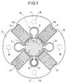
- the reference 1 designates a shaft around which are arranged four magnetic poles 11, 12, 13 and 14, formed of magnetic sheets cut and clamped together by means described below. Between the sheets are placed permanent magnets 21, 22, 23 and 24 with azimuthal magnetization, that is to say perpendicular to the axis O of the shaft and to the radii from this point. Two neighboring magnets have opposite poles north (N) or south (S) of the same name.
- the magnets are arranged in the housings left by the sheets; they are held radially by polar expansions of the poles, such as those referenced 11A and 11B for the pole 11.
- All of the poles and magnets are fixed using a profile 30 of preferably non-magnetic material, chosen for example from the group consisting of aluminum alloys, copper alloys, austenitic stainless steel, fiberglass and carbon fiber.
- This profile encloses the shaft 1. It is of constant thickness and has the shape of four lobes 31, 32, 33 and 34, circular and almost closed. The lobes are connected two by two by arc portions of a circle having the diameter of that of the tree. These portions, referenced 41, 42, 43 and 44, come into close contact with the shaft.
- FIG. 2 illustrates a method of fixing the sheets in which threaded rods 51 are introduced inside the lobes and are provided with bolts 52 and 53 which enclose the sheets 11, with interposition of end cups 54 and 55.
- the cups also serve as longitudinal stops for the magnets.
- FIG. 3 illustrates a variant in which the fixing of the sheets and the magnets of the rotor is ensured by means of the same cups 54 and 55, but this time fixed by means of rivets 62 and 63, made of preferably non-magnetic material, mounted on the press
- the assembly members are introduced inside the lobes of the profile and also serve to reinforce the profile.
- means can be provided to reinforce the profile.
- These means are for example made up of elastic metal tubes such as steel, split, and which are engaged inside the volumes delimited by the lobes.
- One of these tubes, 91, is shown in FIG. 1. These tubes tend to spread radially, which increases the pressure of the profile on the rotor shaft.
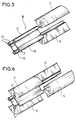
- FIGS 5 and 6 illustrate the mounting of the rotor sheets.
- the sheets are cut and pre-assembled, for example by a process in which each sheet receives a punching causing a cavity on one face and a projection on the opposite face, the projection of a sheet cooperating with the cavity of the adjacent sheet. (This process is known as the Fastec process).
- Two opposite packets 11 and 13 are assembled by engaging them in lobes 31 and 33; to facilitate sliding, diametrically opposite forces are exerted on the other lobes 32 and 34; to mount the packages 12 and 14, diametrically opposite forces F ′ are applied to the already assembled packages 11 and 13.
- the magnets can be mounted by hand in the corresponding housings.
- the invention applies to synchronous motors with multipolar magnets.
Landscapes
- Engineering & Computer Science (AREA)
- Power Engineering (AREA)
- Permanent Field Magnets Of Synchronous Machinery (AREA)
- Reciprocating, Oscillating Or Vibrating Motors (AREA)
- Permanent Magnet Type Synchronous Machine (AREA)
- Iron Core Of Rotating Electric Machines (AREA)
Description
- La présente invention concerne un rotor pour moteur à aimants et s'applique notamment à la réalisation d'un moteur synchrone à aimants permanents.
- Un des problèmes majeurs rencontrés dans la réalisation des moteurs à aimants est celui posé par la fixation des tôles et des aimants entre eux et sur l'arbre du moteur. La fixation doit être robuste pour résister à toutes les contraintes mécaniques (efforts engendrés par la force centrifuge, transmission du couple entre rotor et arbre).
- Par ailleurs, le type de fixation retenu doit être économique, et conduire notamment à des temps de montage réduits.
- Des exemples de réalisation de rotors à aimants permanents sont décrits dans les documents US.A-4 445 062 et FR-A- 20 48 432 qui représentent l'art antérieur.
- L'invention à pour objet un rotor pour un moteur à aimants comprenant au moins une paire de pôles magnétiques entre lesquels sont disposés des aimants à aimantation azimutale, et un arbre de rotation, caractérisé en ce que les pôles et les aimants sont solidarisés entre eux et à l'arbre du moteur par un profilé d'épaisseur constante et présentant en section des lobes en nombre égal à ceux des pôles du moteur, lesdits lobes étant relié deux à deux par des portions courbes sensiblement en arcs de cercle de diamètre voisin de celui de l'arbre du moteur.
- Avantageusement, ledit profilé est choisi dans le groupe comprenant les alliages d'aluminium, les alliages de cuivre, l'acier inoxydable austénitique, la fibre de verre et la fibre de carbone.
- Dans un mode particulier de réalisation, les tôles du rotor sont assemblées au moyen de coupelles d'extrémité serrées par des tiges filetées munies d'écrous.
- En variante, les tôles du rotor sont assemblées au moyen de coupelles d'extrémité serrées par des tiges lisses munies d'anneaux dentelés.
- Dans une autre variante, les tôles du rotor sont assemblées au moyen de coupelles d'extrémité serrées par des rivets.
- Il peut être prévu des moyens pour renforcer le profilé, par exemple des tubes d'acier fendus engagés dans les lobes du profilé.
- L'invention sera bien comprise par la description donnée ci-après d'un mode préféré de réalisation de l'invention en référence au dessin annexé dans lequel:
- la figure 1 est une vue en coupe, par un plan perpendiculaire à son axe de rotation, d'un rotor selon l'invention,
- la figure 2 est une vue en demi-coupe axiale d'un rotor dont les éléments sont assemblés par des tiges filetées,
- la figure 3 est une vue en demi-coupe axiale d'un rotor dont les éléments sont assemblés par des rivets,
- la figure 4 est une vue en demi-coupe axiale d'un rotor dont les éléments sont assemblés par des tiges lisses associées à des anneaux dentelés,
- les figures 5 et 6 illustrent le montage des tôles du rotor sur le profilé.
- L'exemple choisi est celui d'un moteur à quatre pôles.
- Dans la figure 1, la référence 1 désigne un arbre autour duquel sont disposés quatre pôles magnétiques 11, 12, 13 et 14, formés de tôles magnétiques découpées et serrées entre elles par des moyens décrits plus loin. Entre les tôles sont placés des aimants permanents 21, 22, 23 et 24 à aimantation azimutale, c'est-à-dire perpendiculaire à l'axe O de l'arbre et aux rayons partant de ce point. Deux aimants voisins présentent en regard l'un de l'autre des pôles nord (N) ou sud (S) de même nom.
- Les aimants sont disposés dans les logements laissés par les tôles; ils sont maintenus radialement par des épanouissements polaires des pôles, tels que ceux référencés 11A et 11B pour le pôle 11.
- L'ensemble des pôles et des aimants est fixé à l'aide d'un profilé 30 en matériau de préférence amagnétique, choisi par exemple dans le groupe constitué par les alliages d'aluminium, les alliages de cuivre, l'acier inoxydable austénitique, la fibre de verre et la fibre de carbone. Ce profilé vient enserrer l'arbre 1. Il est d'épaisseur constante et présente la forme de quatre lobes 31, 32, 33 et 34, circulaires et presque fermés. Les lobes sont raccordés deux à deux par des portion d'arc d'un cercle ayant pour diamètre celui de l'arbre. Ces portions, référencées 41, 42, 43 et 44, viennent en contact étroit avec l'arbre.
- La figure 2 illustre un mode de fixation des tôles dans lequel des tiges filetées 51 sont introduites à l'intérieur des lobes et sont munies de boulons 52 et 53 venant enserrer les tôles 11, avec interposition de coupelles d'extrémité 54 et 55. Les coupelles servent également de butées longitudinales pour les aimants.
- La figure 3 illustre une variante dans laquelle la fixation des tôles et des aimants du rotor est assuré au moyen des mêmes coupelles 54 et 55, mais cette fois fixées au moyen de rivets 62 et 63, en matériau de préférence amagnétique, montés à la presse
- Dans une autre variante, illustrée dans la figure 4, les mêmes coupelles 54 et 55 sont enserrées grâce à des tiges lisses 71 coopérant avec des anneaux dentelés 72 et 73 (plus connus dans la terminologie anglaise sous le nom de "grip rings")
- Dans les exemple précédemment décrits, les organes d'assemblages (tiges filetées ou non, rivets) sont introduits à l'intérieur des lobes du profilé et servent également à renforcer le profilé. On peut en variante, introduire ces éléments d'assemblages dans des trous des tôles, comme il est classique de le faire. De tels trous ont été représentés en traits tiretés et référencés 81 à 84 dans la figure 1.
- Dans ce cas, on peut prévoir des moyens pour renforcer le profilé. Ces moyens sont par exemple constitués de tubes en métal élastique tel que l'acier, fendus, et qui sont engagés à l'intérieur des volumes délimités par les lobes. Un de ces tubes, 91, est représenté dans la figure 1. Ces tubes ont tendance à s'épandre radialement, ce qui accroît la pression du profilé sur l'arbre du rotor.
- Les figures 5 et 6 illustrent le montage des tôles du rotor. Les tôles sont découpées et préassemblées, par exemple par un procédé dans lequel chaque tôle reçoit un poinçonnage provoquant une cavité sur une face et une saillie sur la face opposée, la saillie d'une tôle coopérant avec la cavité de la tôle adjacente. (Ce procédé est connu sous le nom de procédé Fastec).
- On assemble deux paquets opposés 11 et 13 en les engageant dans les lobes 31 et 33; pour faciliter le glissement, on exerce des efforts F diamétralement opposés sur les autres lobes 32 et 34; pour monter les paquets 12 et 14, on applique, sur les paquets 11 et 13 déjà montés, des efforts F' diamétralement opposés.
- Le profilé étant élastique, lorsque l'on supprime les efforts F ou F', les tôles restent emprisonnées.
- Les aimants peuvent montés à la main dans les logements correspondants.
- L'invention s'applique aux moteurs synchrones à aimants multipolaires.
Claims (7)
- Rotor pour un moteur à aimants comprenant au moins une paire de pôles magnétiques entre lesquels sont disposés des aimants à aimantation azimutale, et un arbre de rotation, caractérisé en ce que les pôles et les aimants sont solidarisés entre eux et à l'arbre du moteur par un profilé (30) d'épaisseur constante et présentant en section des lobes (31, 32, 33, 34) en nombre égal à ceux des pôles du moteur, lesdits lobes étant reliés deux à deux par des portions courbes (41, 42, 43, 44) sensiblement en arcs de cercle de diamètre voisin de celui de l'arbre (1) du moteur.
- Rotor selon la revendication 1, caractérisé en ce que ledit profilé est choisi dans le groupe comprenant les alliages d'aluminium, les alliages de cuivre, l'acier inoxydable austénitique, la fibre de verre et la fibre de carbone.
- Rotor selon l'une des revendications 1 et 2, caractérisé en ce qu'il comprend des moyens (91) pour renforcer le profilé (30).
- Rotor selon la revendication 3, caractérisé en ce que lesdits moyens comprennent des tubes fendus (91) en métal élastique, engagés à l'intérieur des lobes.
- Rotor selon l'une des revendications 1 à 4, caractérisé en ce que les tôles (11, 12, 13, 14) du rotor sont assemblées au moyen de coupelles d'extrémité (54, 55) serrées par des tiges filetées (51) munies d'écrous (52, 53).
- Rotor selon l'une des revendications 1 à 4, caractérisé en ce que les tôles (11, 12, 13, 14) du rotor sont assemblées au moyen de coupelles d'extrémité (54, 55) serrées par des tiges lisses (71) munies d'anneaux dentelés (72, 73).
- Rotor selon l'une des revendications 1 à 4, caractérisé en ce que les tôles (11, 12, 13, 14) du rotor sont assemblées au moyen de coupelles d'extrémité (54, 55) serrées par des rivets (62, 63).
Priority Applications (1)
| Application Number | Priority Date | Filing Date | Title |
|---|---|---|---|
| AT90403359T ATE102764T1 (de) | 1989-11-27 | 1990-11-27 | Rotor eines motors mit magneten. |
Applications Claiming Priority (2)
| Application Number | Priority Date | Filing Date | Title |
|---|---|---|---|
| FR8915550A FR2655214B1 (fr) | 1989-11-27 | 1989-11-27 | Rotor de moteur a aimants. |
| FR8915550 | 1989-11-27 |
Publications (2)
| Publication Number | Publication Date |
|---|---|
| EP0430795A1 EP0430795A1 (fr) | 1991-06-05 |
| EP0430795B1 true EP0430795B1 (fr) | 1994-03-09 |
Family
ID=9387799
Family Applications (1)
| Application Number | Title | Priority Date | Filing Date |
|---|---|---|---|
| EP90403359A Expired - Lifetime EP0430795B1 (fr) | 1989-11-27 | 1990-11-27 | Rotor de moteur à aimants |
Country Status (9)
| Country | Link |
|---|---|
| US (1) | US5162686A (fr) |
| EP (1) | EP0430795B1 (fr) |
| JP (1) | JPH0757075B2 (fr) |
| AT (1) | ATE102764T1 (fr) |
| DE (1) | DE69007243T2 (fr) |
| DK (1) | DK0430795T3 (fr) |
| ES (1) | ES2052216T3 (fr) |
| FR (1) | FR2655214B1 (fr) |
| WO (1) | WO1991008607A1 (fr) |
Cited By (1)
| Publication number | Priority date | Publication date | Assignee | Title |
|---|---|---|---|---|
| CN102522838A (zh) * | 2011-11-30 | 2012-06-27 | 西安久和能源科技有限公司 | 一种切向式磁钢永磁电机转子 |
Families Citing this family (54)
| Publication number | Priority date | Publication date | Assignee | Title |
|---|---|---|---|---|
| DE4341514A1 (de) * | 1993-12-06 | 1995-06-08 | Siemens Ag | Mit Permanentmagneten bestücktes Läuferblechpaket |
| US6005318A (en) * | 1994-02-04 | 1999-12-21 | Schelenker Enterprises Ltd. | Motor including embedded permanent-magnet rotor and method for making the same |
| US6259180B1 (en) | 1996-07-02 | 2001-07-10 | Schlenker Enterprises, Ltd. | Motor including embedded permanent magnet rotor and method for making the same |
| US5554900A (en) * | 1994-02-04 | 1996-09-10 | Schlenker Enterprises Ltd. | Motor including embedded permanent-magnet rotor |
| US6118186A (en) * | 1994-09-14 | 2000-09-12 | Coleman Powermate, Inc. | Throttle control for small engines and other applications |
| US5929611A (en) * | 1994-09-14 | 1999-07-27 | Coleman Powermate, Inc. | Light weight rotor and stator with multiple coil windings in thermal contact |
| US5900722A (en) * | 1994-09-14 | 1999-05-04 | Coleman Powermate, Inc. | Multimode power converter |
| US6018200A (en) * | 1994-09-14 | 2000-01-25 | Coleman Powermate, Inc. | Load demand throttle control for portable generator and other applications |
| US5705917A (en) * | 1994-09-14 | 1998-01-06 | Coleman Powermate, Inc. | Light weight machine with rotor employing permanent magnets and consequence poles |
| DE69636505T2 (de) | 1995-06-07 | 2007-05-24 | General Electric Co. | Dynamoelektrische Maschine und deren Rotorkonstruktion |
| GB9525546D0 (en) * | 1995-12-14 | 1996-02-14 | Rolls Royce Power Eng | Rotor disc |
| KR200156763Y1 (ko) * | 1997-08-25 | 1999-09-01 | 배길성 | 왕복동형 압축기 |
| FR2780580B1 (fr) * | 1998-06-25 | 2000-11-10 | Valeo Equip Electr Moteur | Machine tournante, tel qu'un alternateur pour vehicule automobile |
| DE19914021C2 (de) * | 1999-03-19 | 2002-01-31 | Siemens Ag | Mehrpoliger, permanenterregter Rotor für eine rotierende elektrische Maschine und Verfahren zur Herstellung eines solchen Läufers |
| GB0001121D0 (en) * | 2000-01-19 | 2000-03-08 | Rolls Royce Plc | Rotor disc |
| FR2821023A1 (fr) * | 2001-02-20 | 2002-08-23 | Leroy Somer Moteurs | Roue motrice a moteur synchrone |
| FR2808627B1 (fr) * | 2000-05-03 | 2002-11-29 | Leroy Somer | Rotor de machine tournante electrique et procede de fabrication |
| US6891299B2 (en) * | 2000-05-03 | 2005-05-10 | Moteurs Leroy-Somer | Rotary electric machine having a flux-concentrating rotor and a stator with windings on teeth |
| ATE227898T1 (de) * | 2000-05-03 | 2002-11-15 | Leroy Somer Moteurs | Elektrische rotierende maschine mit flusskonzentrationsrotor und um zähne gewickelter stator |
| FR2821024B1 (fr) * | 2001-02-20 | 2003-06-13 | Leroy Somer Moteurs | Element d'entrainement tel qu'une roue motrice ou un treuil de levage, comportant un moteur synchrone |
| FR2823616B1 (fr) | 2001-04-17 | 2008-07-04 | Leroy Somer Moteurs | Machine electrique comportant au moins un detecteur de champ magnetique |
| FR2823612B1 (fr) | 2001-04-17 | 2003-06-13 | Leroy Somer Moteurs | Stator de machine tournante electrique comportant des bobines individuelles demontables |
| FR2823614B1 (fr) | 2001-04-17 | 2008-07-11 | Leroy Somer Moteurs | Machine tournante electrique comportant un stator forme de secteurs assembles |
| US6700288B2 (en) * | 2001-08-15 | 2004-03-02 | Drs Power & Control Technologies, Inc. | High speed rotor |
| JP3899885B2 (ja) * | 2001-10-05 | 2007-03-28 | 株式会社日立製作所 | 永久磁石式回転電機 |
| US6913413B2 (en) * | 2002-07-24 | 2005-07-05 | Yao-Kun Yang | Coupling lock |
| RU2231896C2 (ru) * | 2002-07-26 | 2004-06-27 | Государственное образовательное учреждение высшего профессионального образования "Оренбургский государственный университет" | Ротор электрической машины с постоянными магнитами |
| FR2853156A1 (fr) * | 2003-03-31 | 2004-10-01 | Leroy Somer Moteurs | Machine electrique synchrone comportant un stator et au moins un rotor et dispositif de commande associe |
| KR100631533B1 (ko) * | 2004-09-13 | 2006-10-09 | 엘지전자 주식회사 | 비엘디시 모터의 회전자 구조 |
| KR100629335B1 (ko) * | 2004-10-29 | 2006-09-29 | 엘지전자 주식회사 | 전동기와 그 계자 제작 방법과 그를 갖는 세탁기 |
| JP2006197696A (ja) * | 2005-01-12 | 2006-07-27 | Toyota Motor Corp | 回転電機の回転子構造 |
| DE202005005936U1 (de) * | 2005-04-13 | 2006-04-13 | Minebea Co., Ltd., Kitasaku | Rotoranordnung für eine elektrische Maschine, insbesondere einen bürstenlosen Gleichstrommotor |
| TW200701595A (en) * | 2005-06-28 | 2007-01-01 | Delta Electronics Inc | Motor rotor |
| KR101143991B1 (ko) | 2006-04-24 | 2012-05-09 | 주식회사 동서전자 | Lspm 동기모터의 로터 |
| FI118940B (fi) * | 2006-09-27 | 2008-05-15 | Abb Oy | Sähkökoneen roottori |
| EP2262442B1 (fr) | 2008-04-11 | 2015-03-25 | BAL Seal Engineering | Pile de cartouches de connecteurs pour transmission électrique |
| FR2932618B1 (fr) * | 2008-06-16 | 2010-11-19 | Leroy Somer Moteurs | Rotor a aimants permanents et machine tournante comportant un tel rotor |
| DE102008050801A1 (de) * | 2008-10-08 | 2010-04-15 | Pro Diskus Ag | Rotor-Welle-Anordnung für eine elektrische Maschine |
| DE102010022702A1 (de) * | 2010-06-04 | 2011-12-08 | Wilo Se | Rotor mit Permanentmagneten |
| FR2976139B1 (fr) | 2011-05-31 | 2016-04-15 | Moteurs Leroy-Somer | Rotor a aimants permanents et machine tournante comportant un tel rotor. |
| CN202221930U (zh) * | 2011-08-11 | 2012-05-16 | 中山大洋电机制造有限公司 | 一种电机永磁转子结构 |
| US9673671B2 (en) * | 2011-08-11 | 2017-06-06 | Zhongshan Broad-Ocean Motor Manufacturing Co., Ltd. | Permanent magnet rotor |
| US20130038162A1 (en) * | 2011-08-11 | 2013-02-14 | Zhongshan Broad-Ocean Motor Manufacturing Co., Ltd | Motor |
| CN102957237B (zh) * | 2011-08-22 | 2017-02-01 | 德昌电机(深圳)有限公司 | 无刷电机及其电机转子 |
| EP2768126B1 (fr) * | 2011-10-14 | 2018-06-27 | Mitsubishi Electric Corporation | Moteur à aimants permanents |
| JP5858232B2 (ja) * | 2012-02-17 | 2016-02-10 | 日本電産株式会社 | ロータコア、モータ、およびモータの製造方法 |
| DE112012006031A5 (de) * | 2012-03-13 | 2015-02-26 | Brose Fahrzeugteile GmbH & Co. Kommanditgesellschaft, Würzburg | Elektrische Maschine |
| WO2013175832A1 (fr) * | 2012-05-24 | 2013-11-28 | 三菱電機株式会社 | Rotor pour machine électrique tournante, machine électrique tournante et procédé de fabrication de rotor pour machine électrique tournante |
| DE102012105992A1 (de) * | 2012-07-04 | 2013-11-07 | Lloyd Dynamowerke Gmbh & Co. Kg | Element einer elektrischen Maschine mit einer Halterung und einem Permanentmagneten, Bauteil mit wenigstens einem Element sowie eine elektrische Maschine |
| JP2014054061A (ja) * | 2012-09-06 | 2014-03-20 | Fanuc Ltd | 埋込磁石型の電動機回転子 |
| JP6417665B2 (ja) * | 2013-03-21 | 2018-11-07 | 株式会社ジェイテクト | 磁石埋込型ロータ、磁石埋込型ロータの製造方法、及び配向着磁装置 |
| DE102015216051B4 (de) * | 2015-08-21 | 2017-05-18 | Continental Automotive Gmbh | Rotor für eine permanenterregte elektrische Maschine |
| JP6806352B2 (ja) * | 2015-10-13 | 2021-01-06 | 株式会社安川電機 | 回転電機、回転子鉄心の製造方法 |
| CN106357025B (zh) * | 2016-09-22 | 2019-02-15 | 珠海格力电器股份有限公司 | 电机转子以及永磁电机 |
Family Cites Families (6)
| Publication number | Priority date | Publication date | Assignee | Title |
|---|---|---|---|---|
| US2043010A (en) * | 1934-06-25 | 1936-06-02 | Fairbanks Morse & Co | Magneto rotor assembly |
| DE6923929U (de) * | 1969-06-14 | 1970-02-26 | Bosch Gmbh Robert | Vorrichtung zum befestigen von permanenten magneten am polgehaeuse eines elektromotors |
| US3979821A (en) * | 1975-05-09 | 1976-09-14 | Kollmorgen Corporation | Method of manufacturing rare earth permanent magnet rotor |
| US4445062A (en) * | 1978-12-26 | 1984-04-24 | The Garrett Corporation | Rotor assembly having anchors with undulating sides |
| EP0126997B1 (fr) * | 1983-05-02 | 1989-01-25 | Herbert Prof. Dr. Weh | Entraînement électrique |
| FR2655784B1 (fr) * | 1989-12-08 | 1992-01-24 | Alsthom Gec | Moteur a aimants a concentration de flux. |
-
1989
- 1989-11-27 FR FR8915550A patent/FR2655214B1/fr not_active Expired - Lifetime
-
1990
- 1990-11-27 DE DE69007243T patent/DE69007243T2/de not_active Expired - Fee Related
- 1990-11-27 AT AT90403359T patent/ATE102764T1/de not_active IP Right Cessation
- 1990-11-27 DK DK90403359.4T patent/DK0430795T3/da active
- 1990-11-27 EP EP90403359A patent/EP0430795B1/fr not_active Expired - Lifetime
- 1990-11-27 US US07/730,870 patent/US5162686A/en not_active Expired - Fee Related
- 1990-11-27 ES ES90403359T patent/ES2052216T3/es not_active Expired - Lifetime
- 1990-11-27 JP JP3500671A patent/JPH0757075B2/ja not_active Expired - Fee Related
- 1990-11-27 WO PCT/FR1990/000857 patent/WO1991008607A1/fr not_active Ceased
Cited By (1)
| Publication number | Priority date | Publication date | Assignee | Title |
|---|---|---|---|---|
| CN102522838A (zh) * | 2011-11-30 | 2012-06-27 | 西安久和能源科技有限公司 | 一种切向式磁钢永磁电机转子 |
Also Published As
| Publication number | Publication date |
|---|---|
| FR2655214A1 (fr) | 1991-05-31 |
| WO1991008607A1 (fr) | 1991-06-13 |
| US5162686A (en) | 1992-11-10 |
| DK0430795T3 (da) | 1994-07-04 |
| ES2052216T3 (es) | 1994-07-01 |
| DE69007243D1 (de) | 1994-04-14 |
| DE69007243T2 (de) | 1994-06-16 |
| ATE102764T1 (de) | 1994-03-15 |
| EP0430795A1 (fr) | 1991-06-05 |
| FR2655214B1 (fr) | 1992-02-07 |
| JPH04500450A (ja) | 1992-01-23 |
| JPH0757075B2 (ja) | 1995-06-14 |
Similar Documents
| Publication | Publication Date | Title |
|---|---|---|
| EP0430795B1 (fr) | Rotor de moteur à aimants | |
| EP0431514B1 (fr) | Moteur à aimants à concentration de flux | |
| EP1001507B1 (fr) | Machine électrique dont le rotor est spécialement adapté aux hautes vitesses | |
| EP0664410A1 (fr) | Palier magnétique et ensemble comportant une partie statorique et une partie rotorique suspendue par un tel palier | |
| FR2611096A1 (fr) | Carcasse de machine tournante electrique | |
| FR2834142A1 (fr) | Ensemble de frein a courants de foucault | |
| EP0608675A1 (fr) | Moteur électrique de puissance élevée et à vitesse de rotation élevée | |
| WO1987003751A1 (fr) | Moteur electrique synchrone di- ou tetraphase a un etage | |
| EP0378596B1 (fr) | Moteur electrique synchrone di- ou polyphase a rotor en forme de disque | |
| EP0945966A2 (fr) | Moteur électrique | |
| EP0697524A1 (fr) | Pompe à vide turbomoléculaire | |
| FR2492020A1 (fr) | ||
| FR2523379A1 (fr) | Moteur comportant un arbre fixe et son procede d'assemblage | |
| EP0789442B1 (fr) | Transmission de véhicule équipée d'un ralentisseur électrique | |
| FR2629286A1 (fr) | Rotor pour moteur electrique a aimants permanents | |
| EP0789443B1 (fr) | Transmission de véhicule équipée d'un ralentisseur électrique | |
| EP0403714A1 (fr) | Perfectionnements aux transmissions de véhicules équipées de ralentisseurs électriques | |
| EP0687055B1 (fr) | Perfectionnements aux transmissions de véhicules équipées de ralentisseurs à courants de Foucault, et aux organes de fixation pour de telles transmissions | |
| EP0789444B1 (fr) | Transmission de véhicule équipée d'un ralentisseur électrique | |
| EP4113796A1 (fr) | Machine electrique tournante | |
| WO2021191451A1 (fr) | Moteur électrique | |
| EP0418135B1 (fr) | Machine électrique à collecteur | |
| EP0244307A1 (fr) | Perfectionnements apportés aux rotors induits des ralentisseurs électromagnétiques | |
| FR2836301A1 (fr) | Ensemble comprenant un moteur electrique et une pompe hydraulique | |
| WO2011033467A2 (fr) | Rotor de machine asynchrone |
Legal Events
| Date | Code | Title | Description |
|---|---|---|---|
| PUAI | Public reference made under article 153(3) epc to a published international application that has entered the european phase |
Free format text: ORIGINAL CODE: 0009012 |
|
| AK | Designated contracting states |
Kind code of ref document: A1 Designated state(s): AT BE CH DE DK ES FR GB GR IT LI LU NL SE |
|
| 17P | Request for examination filed |
Effective date: 19911202 |
|
| 17Q | First examination report despatched |
Effective date: 19930713 |
|
| GRAA | (expected) grant |
Free format text: ORIGINAL CODE: 0009210 |
|
| AK | Designated contracting states |
Kind code of ref document: B1 Designated state(s): AT BE CH DE DK ES FR GB GR IT LI LU NL SE |
|
| REF | Corresponds to: |
Ref document number: 102764 Country of ref document: AT Date of ref document: 19940315 Kind code of ref document: T |
|
| REF | Corresponds to: |
Ref document number: 69007243 Country of ref document: DE Date of ref document: 19940414 |
|
| GBT | Gb: translation of ep patent filed (gb section 77(6)(a)/1977) |
Effective date: 19940329 |
|
| ITF | It: translation for a ep patent filed | ||
| REG | Reference to a national code |
Ref country code: ES Ref legal event code: FG2A Ref document number: 2052216 Country of ref document: ES Kind code of ref document: T3 |
|
| REG | Reference to a national code |
Ref country code: DK Ref legal event code: T3 |
|
| REG | Reference to a national code |
Ref country code: GR Ref legal event code: FG4A Free format text: 3012089 |
|
| PLBE | No opposition filed within time limit |
Free format text: ORIGINAL CODE: 0009261 |
|
| STAA | Information on the status of an ep patent application or granted ep patent |
Free format text: STATUS: NO OPPOSITION FILED WITHIN TIME LIMIT |
|
| EAL | Se: european patent in force in sweden |
Ref document number: 90403359.4 |
|
| 26N | No opposition filed | ||
| PGFP | Annual fee paid to national office [announced via postgrant information from national office to epo] |
Ref country code: SE Payment date: 19960812 Year of fee payment: 7 |
|
| PGFP | Annual fee paid to national office [announced via postgrant information from national office to epo] |
Ref country code: BE Payment date: 19960903 Year of fee payment: 7 |
|
| PGFP | Annual fee paid to national office [announced via postgrant information from national office to epo] |
Ref country code: LU Payment date: 19961001 Year of fee payment: 7 |
|
| PG25 | Lapsed in a contracting state [announced via postgrant information from national office to epo] |
Ref country code: LU Free format text: LAPSE BECAUSE OF NON-PAYMENT OF DUE FEES Effective date: 19971127 |
|
| PG25 | Lapsed in a contracting state [announced via postgrant information from national office to epo] |
Ref country code: SE Free format text: LAPSE BECAUSE OF NON-PAYMENT OF DUE FEES Effective date: 19971128 |
|
| PG25 | Lapsed in a contracting state [announced via postgrant information from national office to epo] |
Ref country code: BE Free format text: LAPSE BECAUSE OF NON-PAYMENT OF DUE FEES Effective date: 19971130 |
|
| REG | Reference to a national code |
Ref country code: FR Ref legal event code: TP Ref country code: FR Ref legal event code: CD Ref country code: FR Ref legal event code: CA |
|
| REG | Reference to a national code |
Ref country code: CH Ref legal event code: PUE Owner name: GEC ALSTHOM S.A. TRANSFER- KLEBER GIRAUDOUX Ref country code: CH Ref legal event code: PFA Free format text: KLEBER GIRAUDOUX TRANSFER- GEC ALSTHOM PARVEX SA Ref country code: CH Ref legal event code: NV Representative=s name: BOVARD AG PATENTANWAELTE |
|
| BERE | Be: lapsed |
Owner name: S.A. GEC ALSTHOM Effective date: 19971130 |
|
| REG | Reference to a national code |
Ref country code: CH Ref legal event code: PFA Free format text: GEC ALSTHOM PARVEX SA TRANSFER- PARVEX |
|
| EUG | Se: european patent has lapsed |
Ref document number: 90403359.4 |
|
| NLS | Nl: assignments of ep-patents |
Owner name: KLEBER GIRAUDOUX |
|
| NLT1 | Nl: modifications of names registered in virtue of documents presented to the patent office pursuant to art. 16 a, paragraph 1 |
Owner name: PARVEX SA;GEC ALSTHOM PARVEX SA |
|
| REG | Reference to a national code |
Ref country code: ES Ref legal event code: PC2A |
|
| REG | Reference to a national code |
Ref country code: GB Ref legal event code: IF02 |
|
| REG | Reference to a national code |
Ref country code: FR Ref legal event code: GC Ref country code: FR Ref legal event code: CJ |
|
| PGFP | Annual fee paid to national office [announced via postgrant information from national office to epo] |
Ref country code: GR Payment date: 20031029 Year of fee payment: 14 Ref country code: GB Payment date: 20031029 Year of fee payment: 14 |
|
| PGFP | Annual fee paid to national office [announced via postgrant information from national office to epo] |
Ref country code: NL Payment date: 20031030 Year of fee payment: 14 Ref country code: CH Payment date: 20031030 Year of fee payment: 14 |
|
| PGFP | Annual fee paid to national office [announced via postgrant information from national office to epo] |
Ref country code: DE Payment date: 20031103 Year of fee payment: 14 |
|
| PGFP | Annual fee paid to national office [announced via postgrant information from national office to epo] |
Ref country code: DK Payment date: 20031104 Year of fee payment: 14 |
|
| PGFP | Annual fee paid to national office [announced via postgrant information from national office to epo] |
Ref country code: AT Payment date: 20031105 Year of fee payment: 14 |
|
| PGFP | Annual fee paid to national office [announced via postgrant information from national office to epo] |
Ref country code: ES Payment date: 20031119 Year of fee payment: 14 |
|
| PGFP | Annual fee paid to national office [announced via postgrant information from national office to epo] |
Ref country code: FR Payment date: 20031126 Year of fee payment: 14 |
|
| PG25 | Lapsed in a contracting state [announced via postgrant information from national office to epo] |
Ref country code: GB Free format text: LAPSE BECAUSE OF NON-PAYMENT OF DUE FEES Effective date: 20041127 Ref country code: AT Free format text: LAPSE BECAUSE OF NON-PAYMENT OF DUE FEES Effective date: 20041127 |
|
| PG25 | Lapsed in a contracting state [announced via postgrant information from national office to epo] |
Ref country code: ES Free format text: LAPSE BECAUSE OF NON-PAYMENT OF DUE FEES Effective date: 20041129 |
|
| PG25 | Lapsed in a contracting state [announced via postgrant information from national office to epo] |
Ref country code: LI Free format text: LAPSE BECAUSE OF NON-PAYMENT OF DUE FEES Effective date: 20041130 Ref country code: DK Free format text: LAPSE BECAUSE OF NON-PAYMENT OF DUE FEES Effective date: 20041130 Ref country code: CH Free format text: LAPSE BECAUSE OF NON-PAYMENT OF DUE FEES Effective date: 20041130 |
|
| PG25 | Lapsed in a contracting state [announced via postgrant information from national office to epo] |
Ref country code: NL Free format text: LAPSE BECAUSE OF NON-PAYMENT OF DUE FEES Effective date: 20050601 Ref country code: DE Free format text: LAPSE BECAUSE OF NON-PAYMENT OF DUE FEES Effective date: 20050601 |
|
| PG25 | Lapsed in a contracting state [announced via postgrant information from national office to epo] |
Ref country code: GR Free format text: LAPSE BECAUSE OF NON-PAYMENT OF DUE FEES Effective date: 20050602 |
|
| REG | Reference to a national code |
Ref country code: DK Ref legal event code: EBP |
|
| REG | Reference to a national code |
Ref country code: CH Ref legal event code: PL |
|
| GBPC | Gb: european patent ceased through non-payment of renewal fee |
Effective date: 20041127 |
|
| PG25 | Lapsed in a contracting state [announced via postgrant information from national office to epo] |
Ref country code: FR Free format text: LAPSE BECAUSE OF NON-PAYMENT OF DUE FEES Effective date: 20050729 |
|
| NLV4 | Nl: lapsed or anulled due to non-payment of the annual fee |
Effective date: 20050601 |
|
| REG | Reference to a national code |
Ref country code: FR Ref legal event code: ST |
|
| PG25 | Lapsed in a contracting state [announced via postgrant information from national office to epo] |
Ref country code: IT Free format text: LAPSE BECAUSE OF NON-PAYMENT OF DUE FEES;WARNING: LAPSES OF ITALIAN PATENTS WITH EFFECTIVE DATE BEFORE 2007 MAY HAVE OCCURRED AT ANY TIME BEFORE 2007. THE CORRECT EFFECTIVE DATE MAY BE DIFFERENT FROM THE ONE RECORDED. Effective date: 20051127 |
|
| REG | Reference to a national code |
Ref country code: ES Ref legal event code: FD2A Effective date: 20041129 |