EP0430858A2 - Düsenvorrichtung für Wasser unter ultrahohem Druck - Google Patents
Düsenvorrichtung für Wasser unter ultrahohem Druck Download PDFInfo
- Publication number
- EP0430858A2 EP0430858A2 EP90630208A EP90630208A EP0430858A2 EP 0430858 A2 EP0430858 A2 EP 0430858A2 EP 90630208 A EP90630208 A EP 90630208A EP 90630208 A EP90630208 A EP 90630208A EP 0430858 A2 EP0430858 A2 EP 0430858A2
- Authority
- EP
- European Patent Office
- Prior art keywords
- nozzle assembly
- high pressure
- ultra high
- water
- fan tip
- Prior art date
- Legal status (The legal status is an assumption and is not a legal conclusion. Google has not performed a legal analysis and makes no representation as to the accuracy of the status listed.)
- Withdrawn
Links
Images


Classifications
-
- B—PERFORMING OPERATIONS; TRANSPORTING
- B08—CLEANING
- B08B—CLEANING IN GENERAL; PREVENTION OF FOULING IN GENERAL
- B08B3/00—Cleaning by methods involving the use or presence of liquid or steam
- B08B3/02—Cleaning by the force of jets or sprays
- B08B3/026—Cleaning by making use of hand-held spray guns; Fluid preparations therefor
- B08B3/028—Spray guns
-
- B—PERFORMING OPERATIONS; TRANSPORTING
- B05—SPRAYING OR ATOMISING IN GENERAL; APPLYING FLUENT MATERIALS TO SURFACES, IN GENERAL
- B05B—SPRAYING APPARATUS; ATOMISING APPARATUS; NOZZLES
- B05B1/00—Nozzles, spray heads or other outlets, with or without auxiliary devices such as valves, heating means
- B05B1/02—Nozzles, spray heads or other outlets, with or without auxiliary devices such as valves, heating means designed to produce a jet, spray, or other discharge of particular shape or nature, e.g. in single drops, or having an outlet of particular shape
- B05B1/04—Nozzles, spray heads or other outlets, with or without auxiliary devices such as valves, heating means designed to produce a jet, spray, or other discharge of particular shape or nature, e.g. in single drops, or having an outlet of particular shape in flat form, e.g. fan-like, sheet-like
- B05B1/042—Outlets having two planes of symmetry perpendicular to each other, one of them defining the plane of the jet
-
- B—PERFORMING OPERATIONS; TRANSPORTING
- B21—MECHANICAL METAL-WORKING WITHOUT ESSENTIALLY REMOVING MATERIAL; PUNCHING METAL
- B21B—ROLLING OF METAL
- B21B45/00—Devices for surface or other treatment of work, specially combined with or arranged in, or specially adapted for use in connection with, metal-rolling mills
- B21B45/04—Devices for surface or other treatment of work, specially combined with or arranged in, or specially adapted for use in connection with, metal-rolling mills for de-scaling, e.g. by brushing
- B21B45/08—Devices for surface or other treatment of work, specially combined with or arranged in, or specially adapted for use in connection with, metal-rolling mills for de-scaling, e.g. by brushing hydraulically
Definitions
- the invention is an ultra high pressure waterjet demolition and cleaning tool.
- the tool is a portable hand held lance equipped with a nozzle assembly having a fan tip to dispense a relatively flat pattern of ultra high pressure water to a surface or an object.
- Water under pressure discharged from nozzles mounted on hand held guns is commonly used to clean surfaces as floors, walls and equipment and cut into concrete and soil.
- Guns having elongated tubes carrying water under pressure to nozzles which direct streams of water to selected locations are used to clean surfaces and objects. Examples of guns having nozzles for directing one or more streams of water under pressure to a selected location are shown by Andersen in U.S. Patent 3,203,736, McDonald in U.S. Patent 3,514,037 and Aarup in U.S. Patent No. 3,536,151.
- These water cleaning systems use relatively low water pressure which does not erode the nozzle structure.
- Some of the nozzles are provided with transverse V-grooves to provide the nozzle with a broad or generally flat spray pattern.
- the invention is directed to an ultra high pressure water cleaning tool having a nozzle assembly used to remove coatings and flashings from surfaces and objects.
- the nozzle assembly is equipped with a fan tip that produces one or more relatively flat streams of ultra high pressure water.
- the water is discharged through a relatively small orifice open to a flat slot as a relatively flat sheet of ultra high pressure water having uniform distribution of water flow flat stream of water.
- the size of the orifice is maintained over a substantial period of time.
- the nozzle assembly of the invention is used with a tool to direct a generally flat stream of water under ultra high water pressure of at least 25,000 psi which may exceed 100,000 psi.
- the nozzle assembly has a member with a passage connected to a supply of water under ultra high pressure, such as a piston pump which delivers pulsating ultra high pressure water into the passage of the member.
- a head having a chamber open to the assage is mounted on the member.
- the head has an inside wall surrounding the chamber and a discharge opening open to the chamber.
- a fan tip is located in the chamber and held in the head with an annular compressible ring.
- the fan tip has a body with a assage substantially smaller in diameter han the chamber and passage in the membr whereby pulsations of the ultra high pressure water from the water supply are attenuated.
- the body has a transverse slot intersecting the passage in the body forming a discharge orifice allowing ultra high pressure water to flow from the passage in the body into the slot whereby the orifice and slot confine the ultra high pressure water to a generally flat stream of ultra high pressure water and directs the stream of ultra high pressure water to a selected location.
- One embodiment of the nozzle assembly includes a fan tip having a layer of super hard material surrounding the orifice whereby material erosion due to ultra high pressure water flowing through the orifice is minimal.
- a preferred embodiment of the tool having a nozzle assembly has an elongated tubular member having an inlet end and an outlet end.
- a solenoid actuated valve remotely coupled to the inlet end controls the flow of ultra high pressure water into the tubular member.
- a trigger mounted on the tubular member has a switch electrically coupled to the solenoid so that when the trigger is pulled the solenoid is actuated to allow ultra high pressure water to flow through the tubular member and a nozzle assembly mounted on the outlet end of the tubular member. When the trigger is released the switch opens so that the solenoid acts to close the remote valve to terminate the supply of ultra high pressure water to the hose connected to the tubular member.
- the nozzle assembly has a head with an internal chamber, an external recess open to the chamber, and an annular lip between the chamber and external recess.
- the nozzle assembly is connected to a supply of ultra high ressure wate of at least 25,000 psi with a member, such as an elongated tubuar member, having a passage for carrying the water to the chamber within the head.
- a fan tip is retained in the chamber adjacent the annular lip with an annular compressible ring, such as an O-ring. The O-ring surrounds the fan tip and holds it in tight engagement with the head.
- One embodiment of the fan tip has an elongated passage intersected with a flat transverse slot forming a discharge orifice for ultra high pressure water which is directed as a generally flat stream of water toward a selected location.
- the fan tip has a body with a passage open to the dscharge orifice and the chaber in the head.
- the passage in the body has a diameter substantially smaller than the hamber in the head and the passage is te member so that pulsations of the ultra high pressure water from the water supply are attenuated to reduce erosion of the metal of the body of the fan tip and mantain uniform distribution of water flow to the flat stream of water.
- the slot and orifice are made of hard metal which has long wear life and maintains the dimensions of the orifice to provide an energy efficient and uniform stream of water.
- Another embodiment of the fan tip has a layer of super hard material, such as polycrystalline diamond, cubic boron nitride, or BORAZON, bonded to a base.
- An elongated oval orifice in the super hard material and base establishes a uniform general flat stream of ultra high pressure water that is directed to a selected location.
- the nozzle assembly in one embodiment has an angularly adjustable head used to change the orientation of the generally flat streams of ultra high pressure water.
- Another embodiment of the nozzle assembly has a body supporting a pair of nozzle units. Each nozzle unit has a sleeve accommodating a fan tip. The sleeve is threaded into the body so that it can be removed from the body to allow the fan tip to be replaced.
- Figure 1 is a side view of an ultra high pressure water lance equipped with a nozzle assembly having a fan tip;
- Figure 2 is an enlarged sectional view taken along line 2-2 of Figure 1;
- Figure 3 is an enlarged side view of the nozzle assembly of the lance of Figure 1;
- Figure 4 is an enlarged end view of the lance taken along line 4-4 in Figure 3 looking in the direction of arrows;
- Figure 5 is a sectional view taken along line 5-5 of Figure 3;
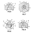
- Figure 6 is an enlarged cross-sectional view of the fan tip shown in Figure 5;
- Figure 7 is an enlarged sectional view taken along line 7-7 of Figure 5;
- Figure 8 is an end view of the outer end of the fan tip
- Figure 9 is a sectional view taken along line 9-9 of Figure 8.
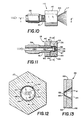
- Figure 11 is an enlarged sectional view taken along the line 11-11 of Figure 10;
- Figure 12 is an enlarged sectional view taken along line 12-12 of Figure 11;
- Figure 13 is a sectional view taken along line 13-13 of Figure 12;
- Figure 14 is a plan view of a second modification of the nozzle assembly equipped with a fan tip
- Figure 15 is a front view of the nozzle assembly of Figure 14;
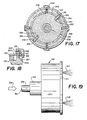
- Figure 16 is an enlarged sectional view taken along line 16-16 of figure 14;
- Figure 17 is a sectional view taken along line 17-17 of Figure 16;
- Figure 18 is a sectional view taken along line 18-18 of Figure 15;
- Figure 19 is a third modification of the nozzle assembly equipped with a pair of fan tips
- Figure 20 is a front view of the nozzle assembly of Figure 19.
- Figure 21 is a sectional view taken along line 21-21 of Figure 20.
- Ultra high pressure water is water under pressure of at least 25,000 psi.
- tool 10 is used to remove coatings, such as paint and oils, and flashings from surfaces and objects.
- Tool is a light-weight, hand held apparatus that is manually manipulated to direct a generally flat stream or curtain of ultra high pressure water toward a surface for cleaning and removing objects and coatings from the surface.
- Tool 10 has an elongated rigid pipe or tubular member 11 of metal.
- Pipe 11 has an inlet end 12 connected to an ultra high pressure water source 13 with a hose.
- a power driven piston pump can be used to provide a supply of water under pressure of at least 25,000 psi.
- An intensifier can be used to elevate the pressure of the water from the range of 25,000 psi to over 100,000 psi.
- the ultra high pressure water has some pulsations due to the operation of the pump and intensifier.
- a remote control valve 25 is interposed in the line or hose that connects the ultra high pressure water source 13 to inlet end 12.
- Remote control valve 25 is an electrically operated valve, such as a solenoid valve, that utilizes low voltage to control the supply of ultra high pressure water to pipe 11.
- Pipe 11 has an outlet end 14 attached to a nozzle assembly indicated generally at 16.
- Nozzle assembly 16 is used to establish a generally flat stream or curtain of water under ultra high pressure that is directed to a selected location by the operator of the tool. The configuration of the generally flat water stream 17 is maintained over a substantial period of time as nozzle assembly 16 has a minimum of material erosion.
- Nozzle assembly 16 has an orifice 61 that controls the dimensions and pattern of the stream of water to provide uniform distribution of water flow. The results are a high quality uniform stream of water and efficient use of pumping energy.
- Tool 10 is manually controlled by the operator with the use of a trigger mechanism indicated generally at 18 and a shoulder rest 26.
- Trigger mechanism 18 has a body 19 that is secured to the mid-portion of pipe 11. The lower portion of body 19 has a downwardly extended hand grip 20.
- a movable member or pivotally mounted lever 21 is located on the front side of body 19 and grip 20. Lever 21 engages an actuator 22 for an electrical switch 30 located within body 19. Switch 30 is connected with an electrical cord or line 24 to the electrical controls for remote control valve 25.
- a guard 23 extended from the upper portion of body 19 in front of lever 21 is secured at its lower end to the bottom of hand grip 20. Guard 23 protects the hand of the operator, as well as prevents inadvertent actuation of lever 21.
- actuator 22 When lever 21 is compressed, actuator 22 is operated to turn switch 30 to an on position. This energizes the electrical controls for remote control valve 25, allowing ultra high pressure water to flow through valve 25 and into pipe 11. The water is discharged through nozzle assembly 16 in a generally flat high pressure stream to a selected location.
- shoulder rest 26 has a generally rectangular configuration with a broad concave rear surface that is adapted to engage the shoulder of the operator.
- the center portion of the front of shoulder rest 26 is connected to a downwardly directed arm 27.
- the lower end of arm 27 is attached to pipe 11 with a clamp 28 seen in Figure 2.
- a plurality of nut and bolt assemblies 29 secure clamp 28 to the lower end of arm 27.
- the nut and bolt assemblies 29 allow shoulder rest 26 to be adjusted along the length of pipe 11 from trigger mechanism 18 to the inlet end of the pipe. This adjustment allows for a comfortable positioning of the shoulder rest on the operator and a proper spatial relationship between shoulder rest 26 and trigger mechanism 18.
- nozzle assembly 16 has a coupling 31 with a longitudinal passage 32 for carrying water under ultra high pressure from pipe 11 through a nipple 38 carrying a nozzle head 47.
- Coupling 31 has an inlet threaded end 33 adapted to receive the threads of the outlet end 14 of pipe 11.
- a nut 34 having an annular seal 36 is threaded about end 14 and forced into an engagement with the end of coupling 31.
- the opposite end of coupling 31 has a threaded outlet end 37 for receiving threaded end 39 of nipple 38.
- End 39 has a cone-shaped surface positioned in tight engagement with a cone seat 41, forming a seal between the end of nipple 38 and coupling 31.
- a nut 43 carrying an annular seal 44 is threaded onto nipple 38 and engages the end of coupling 31 to lock and seal nipple 38 onto coupling 31.
- the outlet end of nipple 38 has a threaded end 51 that is threaded into a threaded bore 48 of the nozzle head 47.
- Threaded bore 48 terminates in a seat 49 that is in tight engagement with a cone end 52 of nipple 38 to mount head 47 in sealing relationship with nipple 38.
- Seat 49 has a circular right angle edge that forms a crush seal with cone end 52.
- Transverse holes 50 bleed liquid from the area around cone end 52.
- Head 47 has an internal chamber 53 formed by a cylindrical inside wall 58 having a diameter larger than passage 46 of nipple 38.
- the outer forward end of head 47 has a flat front face 54 with a central cone-shaped recess 56 concentric with chamber 53.
- An annular lip 57 forms the inner portion of recess 56 and provides an annular shoulder for a fan tip 59.
- Fan tip 59 has a body 63 located in chamber 53.
- An annular holder 62 shown as an O-ring, surrounds body 63 to hold fan tip 59 on head 47.
- O-ring 62 is an annular, compressible plastic or rubber member that is deformed and under compression to hold fan tip 59 in the forward end of chamber 58 of head 47.
- O-ring 62 centers fan tip 59 in chamber 53 and allows fan tip 59 to be removed and replaced with another tip.
- fan tip 59 has an elongated, generally flat orifice 61 which directs a generally flat stream of ultra high pressure water away from head 47 toward a selected location, such as a floor, street, walk, wall and the like.
- fan tip 59 has a metal base or body 63 with a smooth, cylindrical outer surface 64.
- the proximal end of body 63 has a central cylindrical bore 66 adapted to face chamber 53.
- the distal end of body 63 has an annular transverse shoulder 67 surrounding a forwardly projected truncated boss 68.
- the outer face 69 of boss 68 is flat.
- the central interior part of body 63 and boss 68 has a cone-shaped recess or passage 71 open to bore 66 and orifice 61.
- the assage 71 and orifce 61 hav diameters that are substantially smaller than the diameters of chambr 53 and pasage 44.
- the diameter of passage 44 is four to ten times larger than the diameter of passage 71.
- Orific 61 is smaler tha passage 71 whereby the pulsations of the ultra high pressure fom the water supply are attenuated due to the large column of water in passage 44 and chamber 53.
- the wall 75 of body 63 forming recess 71 tapers in a forward direction and intersects a mid-portion of a transverse slot 72 extended diametrically across boss 68, as seen in Figure 8.
- the opening or orifice 61 is located in the mid-portion of slot 72.
- Slot 72 has a uniform width along its length that is smaller than the diameter of the rounded outlet end 76 of passage 71.
- the length of wall 75 in the longitudinal direction is greater than the diameter of the inlet end of passage 71.
- the length of wall 75 can be twice the diameter of the inlet end of passage 71.
- the entire wall 75 is ground smooth to remove burrs and like projections to reduce material erosion due to ultra high pressure water flowing through passage 71.
- Laterally spaced, generally trapezoidal shaped side walls 73 and 74 are parallel to each other to form transverse slot 72 with a uniform width throughout its length.
- the uniform width of slot 72 is preferably one half the diameter of outer end 76 of passage 71.
- the height of slot 72 is greater than the diameter of the outer end 76 of passage 71.
- the height of slot 72 is twice the diameter of the outer end 76 of passage 71.
- Side walls 73 and 74 restricts the lateral expansion of stream 17 moving from orifice 61.
- Wall 75 has a maximum 20 degree taper from its center line and terminates in a generally spherical upper or distal end 76.
- the distal end 76 of passage 71 is intersected with slot 72 to form orifice 61 in layer
- Fan tip body 63 is preferably made of high strength material, such as stainless steel, having a Rockwell hardness of 58 to 60. Other types of durable high strength material that are not corrosive to water and are not readily eroded by rapidly moving, ultra high pressure water can be used for body 63.
- a super hard layer 65 having the orifice can be bonded to body 63. This layer is a hard wear resistant material including, but not limited to, polycrystalline diamond, cubic boron nitride, BORAZON, and Pyrolite carbon.
- Nozzle assembly 116 establishes a generally flat stream or curtain of ultra high pressure water that can be directed to selected locations by the operator of the tool.
- Nozzle assembly 116 is mounted on a manual operated tool such as tool 10 shown in Figure 1.
- Other types of tools and machines accommodating ultra high water pressure can be used with nozzle assembly 116.
- a stream of water 117 is discharged as a generally flat pattern forwardly from nozzle assembly 116.
- the stream has generally uniform water distribution to provide high quality flow that efficiently uses the pumping energy that generates the ultra high pressure of the water.
- Nozzle assembly 116 is connected with nipple 138 to the tool.
- Nipple 138 has a threaded end 151 and a central elongated passage 146 as seen in Figure 11.
- Nozzle assembly 116 has a head 147 that is threaded on threaded end 151.
- Head 147 has an annular wall or bore 158 surrounding a chamber 153.
- Wall 158 has an outwardly directed step having a annular edge 149.
- the forward end of nipple 138 has a forwardly directed cone 152 located in tight engagement with the edge 149 when head 147 is threaded on threads 151.
- Edge 149 forms a seat that provides a crush seal with cone 152.
- Transverse bores 150 bleed liquid from the area around cone and 152.
- the forward end of head 147 has a flat front face 154 with a central cone-shape recess 156 concentric with chamber 153.
- An annular lip 157 forms the inner portion of recess 156 and provides a annular shoulder for a fan tip 159.
- Fan tip 159 is retained in chamber 153 with an annular holder 160, such as an O-ring, that is deformed and under compression. As shown in Figure 12, annular member 160 surrounds outer peripherial surface 168 of fan tip 159 and engages cylindrical wall 158 of head 147 surrounding chamber 153.
- Fan tip 159 has a cylindrical base 162, such as stainless steel or carbide, and a layer 163 of super hard material.
- the super hard material is abrasion resistant and non-corrosive to water and air. Examples of super hard materials inculde polycrystalline diamond, cubic boron nitride, and BORAZON. Other hard materials can be used as layer 163 of super hard material.
- the super hard layer 163 is bonded to the one side of base 162.
- Fan tip 159 can be formed by assembling fine diamond powder and carbide into a refractory type mold. The assembly is then subjected to pressures that are near one million psi and heated by electrical current to about 3,000 degrees F. The mold is then allowed to cool and the pressure released. Under these conditions the individual diamond crystals sinter together to form a solid mass.
- An elongated generally oval slot or orifice 161 is cut in base 162 and layer 163 with an EDM wire cutting procedure.
- the side wall 164 of the orifice tappers outwardly in the forward direction providing the super hard material with an acute angled edge 167 surrounding the inlet of orifice 161.
- Super hard material of layer 163 being extremely abrasive resistant maintains the shape of edge 167 thereby sustains the shape of the inlet end of orifice 161 for a prolonged period of use.
- the results are an improved generally flat stream quality, a more efficient use of the energy of the pumping system, uniform distribution of water flow over the width of stream 117 of water, and long wear life of fan tip 159.
- the stream 117 of water does not have concentrated energy areas whereby the cleaning and scarifying action is uniform over the entire width of stream 117 of water.
- Nozzle assembly 216 generates a generally flat stream or curtain of ultra high pressure water that can be directed to selected locations by the operator of the tool.
- the stream is angularly adjustable to provide the operator with additional control during the use of the nozzle assembly.
- Nozzle assembly 216 can be mounted on a manually operated tool such as tool 10 slown in Figure 1.
- Other types of tools and machines accommodating ultra high water pressure can be used with nozzle assembly 216.
- the high pressure stream of water 217 is discharged as a generally flat pattern having uniform water distribution to provide high quality flow that efficiently utilizes the pumping energy that generates the ultra high pressure of the water.
- Nozzle assembly 216 is secured to a pipe 218 having a passage 219 for receiving ultra high pressure water indicated by arrow 221.
- Nozzle assembly 216 has a body 222 having a threaded bore 223.
- the base of the bore has a cone recess face 224 that accommodates conical end 226 of pipe 218.
- Pipe 218 is threaded into the threaded bore 223 to hold conical end 226 in sealing relation with cone recess face 224.
- a transverse bore 228 bleeds the liquid from the area around cone end 226.
- the end of pipe 218 is aligned with a passage 227 in body 222 leading to a chamber 232 of a head 229.
- Head 229 has a cylindrical threaded stem 230 surrounding passage 232.
- Stem 230 is turned into a threaded bore 231 in the outer end of body 222.
- the outer end of stem 230 has an annular groove 233 accommodating an annular seals 234 located in engagement with the inner end of bore 231.
- Base 222 has a transverse port 236 open to the side of stem 231 to collect fluid that may bypass seals 234.
- Head 239 has an inwardly directed annular lip 237 surrounding a discharge opening 238. Annular lip 237 forms the inner portion of the chamber 232 and provides an annular shoulder for a fan tip 239.
- Fan tip 239 is an annular member having the structure of fan tip 59 as shown in Figures 6, 8 and 9. Fan tip 159 shown in Figure 13 can be used with head 229.
- a annular member or O-ring 241 retains fan tip 239 in chamber 232 in engagement with annular lip 237.
- Fan tip 239 has a slot discharge orifice 242 which reduces the concentration of energy areas so that the cleaning and scarifying action of the stream of water 217 is substantially uniform over its entire width. As shown in full and broken lines in Figure 15, the angular orientation of orifice 242 can be changed.
- a sleeve 243 surrounds body 222 and head 229.
- a cylindrical collar 243 rotatably mounts sleeve 243 on pipe 218 adjacent body 222.
- the outer end of sleeve 243 is rotatably mounted on body 222.
- An annular cap 246 is mounted on the outer end of sleeve 243.
- Cap 246 surrounds a ring 247 located in surface engagement with the end of sleeve 243. Ring 247 can be integral with cap 246.
- the outer end of sleeve 243 has two circumferentially placed space slots 251 and 252.
- a first pin 256 located in a bore 257 in head 229 projects through slot 251 into a hole 261 in ring 247.
- a second pin 258 is located in a bore 259 in body 229 diametrically opposite pin 256.
- Pin 258 extends through slot 252 and into a hole 262 in ring 247.
- Pins 256 and 258 connected head 229 with the cap 246 and ring 247.
- Cap 246 and body 229 can be rotated to longitudinally move head 229 relative to body 222 to turn fan tip 239 thereby changing the angular position of discharge orifice 242 as shown in broken lines in Figure 15.
- Sleeve 243 can be rotated during use of nozzle assembly 216 as the sleeve extends rearwardly of body 222 so that the operator can turn the sleeve remote from the high pressure stream of water discharging from the fan tip.
- Nozzle assembly 316 discharges a pair of ultra high pressure streams of water 317 and 318 to a desired location.
- the nozzle assembly 316 can be rotated whereby streams 317 and 318 move in a circular pattern over a surface.
- Nozzle assembly 316 is connected to a pipe 319 having a passage 321 for delivering a ultra high pressure water indicated by arrow 322 to nozzle assembly 316.
- Pipe 319 can be pipe 11 as shown in Figure 1.
- Nozzle assembly 316 has a generally flat body 323 having a lateral boss 324.
- Boss 324 has a threaded bore 326 accommodating a threaded end of pipe 319.
- the end of pipe 319 has a cone surface located in sealing relation with a cone face 327 at the base of boss 324.
- Body 323 has an axial bore 328 open to the passage 321 in pipe 319 and connected to a transverse or radial passage 329. The ends of passage 329 are closed with plugs 331 and 332 to retain seals 333 and 334 in passage 329.
- Body 323 carries a pair of nozzle units indicated generally at 336 and 337.
- Nozzle unit 336 has a sleeve 338 located within a threaded bore 339 of body 323.
- Sleeve 338 has an internal chamber 341 connected with a port 342 to passage 329.
- the inner portion of sleeve 338 has a groove 343 accommodating a seal assembly 344.
- the outer end of sleeve 338 has an inwardly directed annular lip 346 surrounding an openning 347 and forming a shoulder for a fan tip 348.
- Fan tip 348 has a generally slot discharge orifice 349.
- Fan tip 348 is the same as the fan tip 59 as shown in Figures 6, 8 and 9.
- Fan tip 159 as shown in Figures 12 and 13 can be used in lieu of fan tip 348.
- An O-ring or annular member 351 surounding fan tip 348 retains the fan tip in passage 341 adjacent annular lip 346.
- Sleeve 338 has an annular outwardly directed rim 352 having a plurality of slots 353 for accommodating a tool used to turn sleeve 338 into the threaded bore 339.
- the angular orientation of slot discharge orifice 349 can be changed by turning sleeve 338.
- Body 323 has a second threaded bore 356 accommodating a sleeve 354 of nozzle unit 337.
- Sleeve 354 has a chamber 357 connected with port 358 to passage 329.
- the inner end of sleeve 354 has an annular groove 359 accommodating a seal assembly 361.
- the outer end of sleeve 354 has an inwardly directed annular lip 362 surrounding an opening 363 and providing a shoulder for supporting a fan tip 364.
- Fan tip 364 is identical to the fan tip 348 and the fan tip 59 as shown in Figures 6, 8 and 9.
- Fan tip 364 has a slot discharge orifice 366.
- An annular member or O-ring 367 surrounds fan tip 364 and retains the fan tip 364 in engagement with the annular lip 362.
- Sleeve 354 has an outwardly directed annular rim 368 having a plurality of circumferentially spaced slots 369.
- a turning tool has projections that are located in the slots to permit the turning of the sleeve 354 into threaded bore 356.
- the angular orientation of slot discharge orifice 366 can be changed by turning sleeve 354.
- a circular plate 371 is secured to the outer end of body 323. As shown in Figures 20 and 21 plate 371 has a pair of circular openings 372 and 373 that surround the outer ends of sleeves 338 and 354. Plate 371 serves as a guide and protection member for base 323 and nozzle units 336 and 337 during use of nozzle assembly 316.
- a turning tool is used to remove sleeves 338 and 354 from body 323.
- the tool has teeth that fit into slots 353 and 369 so that sleeves 338 and 354 can be turned out of body 323.
- the fan tips 348 and 364 can then be removed and replaced with new fan tips.
- the fan tips 348 and 364 are forced out of the chambers 341 and 357.
- the new fan tips are then reinserted into the chambers 341 and 357 and retained therein with O-rings 351 and 367.
- the tool is then used to turn sleeves 338 and 354 back into body 323 as shown in Figure 21.
- the nozzle assembly 316 is used with the ultra high water pressure to clean and scarify a surface of foreign materials.
- Nozzle assembly 316 can be rotated about the axis of passage 328 to move nozzle units 336 and 337 in a circular path. Movement of nozzle assembly 316 as it is rotating relative to a surface will clear a path on the surface.
Landscapes
- Nozzles (AREA)
- Cleaning By Liquid Or Steam (AREA)
- Perforating, Stamping-Out Or Severing By Means Other Than Cutting (AREA)
Applications Claiming Priority (2)
| Application Number | Priority Date | Filing Date | Title |
|---|---|---|---|
| US444288 | 1982-11-24 | ||
| US07/444,288 US5052624A (en) | 1988-03-11 | 1989-12-01 | Ultra high pressure water cleaning tool |
Publications (2)
| Publication Number | Publication Date |
|---|---|
| EP0430858A2 true EP0430858A2 (de) | 1991-06-05 |
| EP0430858A3 EP0430858A3 (en) | 1992-07-01 |
Family
ID=23764282
Family Applications (1)
| Application Number | Title | Priority Date | Filing Date |
|---|---|---|---|
| EP19900630208 Withdrawn EP0430858A3 (en) | 1989-12-01 | 1990-11-30 | Nozzle assembly for ultra-high pressure water |
Country Status (3)
| Country | Link |
|---|---|
| US (1) | US5052624A (de) |
| EP (1) | EP0430858A3 (de) |
| JP (1) | JPH03184800A (de) |
Cited By (9)
| Publication number | Priority date | Publication date | Assignee | Title |
|---|---|---|---|---|
| WO1998042448A1 (en) * | 1997-03-21 | 1998-10-01 | Nordson Corporation | Spray gun with rotatably adjustable nozzle |
| RU2169049C1 (ru) * | 2000-01-26 | 2001-06-20 | Тюменский государственный университет | Способ очистки твердой поверхности от жидких загрязнений в виде пленки смачивания или капель |
| EP1832347A1 (de) | 2002-02-13 | 2007-09-12 | Delavan Limited | Lochplatte einer Spritzdüse |
| WO2007111803A1 (en) * | 2006-03-24 | 2007-10-04 | Illinois Tool Works Inc. | Spray device having removable hard coated tip |
| DE4341870B4 (de) * | 1992-12-08 | 2008-03-13 | Flow International Corp., Kent | Ultrahochdruck-Flachstrahl-Düse |
| AU2007203277B2 (en) * | 2002-02-13 | 2009-01-08 | Delavan Limited | Orifice disc for a spray nozzle |
| US7611079B2 (en) | 2002-02-13 | 2009-11-03 | Delavan Limited | Spray nozzle |
| WO2009154567A1 (en) * | 2008-06-20 | 2009-12-23 | Aem Singapore Pte Ltd | A wear-resistant high-pressure water jet nozzle |
| US8579213B2 (en) | 2012-02-27 | 2013-11-12 | Delavan Inc. | Single circuit multiple spray cone pressure atomizers |
Families Citing this family (55)
| Publication number | Priority date | Publication date | Assignee | Title |
|---|---|---|---|---|
| JP2594091Y2 (ja) * | 1991-08-30 | 1999-04-19 | 川崎重工業株式会社 | アブレイシブウォータージェットノズル構造 |
| JP2588249Y2 (ja) * | 1992-06-29 | 1999-01-06 | 旭ダイヤモンド工業株式会社 | 高圧用ウォータージェットノズル |
| CA2084543A1 (en) * | 1992-12-04 | 1994-06-05 | David N. Mccue | Fire hose support |
| DE4341869A1 (de) * | 1992-12-08 | 1994-06-09 | Flow Int Corp | Entfernung von harten Überzügen mit Ultrahochdruck-Flachstrahlen |
| US5961053A (en) * | 1994-02-18 | 1999-10-05 | Flow International Corporation | Ultrahigh-pressure fan jet nozzle |
| US5361286A (en) * | 1993-05-19 | 1994-11-01 | General Electric Company | Method for in situ cleaning of inlet mixers |
| US5418824A (en) * | 1993-05-19 | 1995-05-23 | General Electric Company | In situ inlet mixer cleaning system |
| DE4411554A1 (de) * | 1994-04-02 | 1995-10-05 | Bosch Gmbh Robert | Einspritzventil |
| AU4604196A (en) * | 1994-12-29 | 1996-07-31 | Alliant Techsystems Inc. | High pressure washout of chemical agents |
| AU4642796A (en) * | 1994-12-29 | 1996-07-24 | Michael S Cypher | High pressure washout of explosive agents |
| US5713878A (en) * | 1995-06-07 | 1998-02-03 | Surgi-Jet Corporation | Hand tightenable high pressure connector |
| US6216573B1 (en) | 1995-06-07 | 2001-04-17 | Hydrocision, Inc. | Fluid jet cutting system |
| US5871462A (en) * | 1995-06-07 | 1999-02-16 | Hydrocision, Inc. | Method for using a fluid jet cutting system |
| US5944686A (en) * | 1995-06-07 | 1999-08-31 | Hydrocision, Inc. | Instrument for creating a fluid jet |
| JP3522049B2 (ja) * | 1996-06-17 | 2004-04-26 | 京セラ株式会社 | 液体噴射ノズル |
| US5853128A (en) * | 1997-03-08 | 1998-12-29 | Bowen; Howard S. | Solid/gas carbon dioxide spray cleaning system |
| SE521301C2 (sv) * | 1998-12-08 | 2003-10-21 | Eftec Europe Holding Ag | Tätningsmunstycke |
| DE19918257A1 (de) * | 1999-04-22 | 2000-11-23 | Lechler Gmbh & Co Kg | Hochdrucksprühdüse |
| US6375635B1 (en) | 1999-05-18 | 2002-04-23 | Hydrocision, Inc. | Fluid jet surgical instruments |
| US6425805B1 (en) * | 1999-05-21 | 2002-07-30 | Kennametal Pc Inc. | Superhard material article of manufacture |
| US6451017B1 (en) | 2000-01-10 | 2002-09-17 | Hydrocision, Inc. | Surgical instruments with integrated electrocautery |
| US6511493B1 (en) | 2000-01-10 | 2003-01-28 | Hydrocision, Inc. | Liquid jet-powered surgical instruments |
| US6752685B2 (en) | 2001-04-11 | 2004-06-22 | Lai East Laser Applications, Inc. | Adaptive nozzle system for high-energy abrasive stream cutting |
| ES2290293T3 (es) | 2001-04-27 | 2008-02-16 | Hydrocision, Inc. | Cartuchos de bombeo a alta presion para aplicaciones de bombeo e infusion medicas y quirurgicas. |
| US7211435B2 (en) * | 2001-06-21 | 2007-05-01 | Sierra Sciences, Inc. | Telomerase expression repressor proteins and methods of using the same |
| US6817550B2 (en) | 2001-07-06 | 2004-11-16 | Diamicron, Inc. | Nozzles, and components thereof and methods for making the same |
| EP1412122A4 (de) * | 2001-07-09 | 2008-03-19 | Jonathan Mohler | Thermitschneidbrennerdüse |
| JP2004537380A (ja) | 2001-08-08 | 2004-12-16 | ハイドロシジョン・インコーポレーテッド | 高圧迅速分離ハンドピースを備えた医療器具 |
| US7464630B2 (en) * | 2001-08-27 | 2008-12-16 | Flow International Corporation | Apparatus for generating and manipulating a high-pressure fluid jet |
| CA2495911C (en) * | 2001-11-21 | 2011-06-07 | Hydrocision, Inc. | Liquid jet surgical instruments incorporating channel openings aligned along the jet beam |
| US10363061B2 (en) | 2002-10-25 | 2019-07-30 | Hydrocision, Inc. | Nozzle assemblies for liquid jet surgical instruments and surgical instruments for employing the nozzle assemblies |
| US8162966B2 (en) | 2002-10-25 | 2012-04-24 | Hydrocision, Inc. | Surgical devices incorporating liquid jet assisted tissue manipulation and methods for their use |
| KR200344321Y1 (ko) * | 2003-12-22 | 2004-03-09 | 주식회사 젯텍 | 디플래시장치용 초고압 액상 세척매체의 분사노즐 |
| US7040959B1 (en) | 2004-01-20 | 2006-05-09 | Illumina, Inc. | Variable rate dispensing system for abrasive material and method thereof |
| USD538684S1 (en) | 2005-11-21 | 2007-03-20 | Black & Decker Inc. | Laser level |
| US8712539B2 (en) * | 2006-04-12 | 2014-04-29 | Medtronic, Inc. | Rule-based stimulation program search |
| US7828226B2 (en) * | 2007-04-26 | 2010-11-09 | Phillip John Martin | Handheld device and method for clearing obstructions from spray nozzles |
| US20100072301A1 (en) * | 2008-09-19 | 2010-03-25 | Miro Cater | Discharge device |
| US8394205B2 (en) * | 2009-02-02 | 2013-03-12 | Mac & Mac Hydrodemolition Inc. | Pipe scarifying system and method |
| DE102010051227A1 (de) | 2010-11-12 | 2012-05-16 | Dental Care Innovation Gmbh | Düse zur Abstrahlung von flüssigen Reinigungsmitteln mit darin dispergierten abrasiven Partikeln |
| US9216441B2 (en) * | 2011-03-01 | 2015-12-22 | Gardner Denver Water Jetting Systems, Inc. | Water jetting gun having a removable valve cartridge, an adjustable hand grip and an adjustable shoulder stock |
| KR101280865B1 (ko) | 2011-03-17 | 2013-07-03 | 주식회사 승일 | 분사노즐 및 이를 이용한 분사장치 |
| JP5883286B2 (ja) * | 2011-12-16 | 2016-03-09 | リョービ株式会社 | 高圧洗浄機用ノズル及び高圧洗浄機 |
| US9238122B2 (en) * | 2012-01-26 | 2016-01-19 | Covidien Lp | Thrombectomy catheter systems |
| US20140203103A1 (en) * | 2012-12-18 | 2014-07-24 | Psc Industrial Outsourcing, Inc. | Water blasting gun safety system |
| CN107175227A (zh) * | 2016-03-10 | 2017-09-19 | 核动力运行研究所 | 蒸汽发生器二次侧第一支撑板下表面水力冲洗装置 |
| USD825741S1 (en) | 2016-12-15 | 2018-08-14 | Water Pik, Inc. | Oral irrigator handle |
| KR102625450B1 (ko) | 2017-03-16 | 2024-01-16 | 워어터 피이크, 인코포레이티드 | 구강 작용제와 함께 사용하기 위한 구강 세척기 핸들 |
| US10399129B2 (en) * | 2018-01-22 | 2019-09-03 | Terydon, Inc. | Reaction force nozzle |
| US10618084B2 (en) | 2018-01-22 | 2020-04-14 | Terydon, Inc. | Reaction force nozzle |
| US11554461B1 (en) | 2018-02-13 | 2023-01-17 | Omax Corporation | Articulating apparatus of a waterjet system and related technology |
| US11110484B2 (en) * | 2019-09-12 | 2021-09-07 | Kudachi Business Consultants, LLC | Dispensing paintbrush |
| CN110814131A (zh) * | 2019-12-09 | 2020-02-21 | 涌镇液压机械(上海)有限公司 | 台肩孔毛刺去除装置 |
| FR3107761A1 (fr) * | 2020-02-27 | 2021-09-03 | Arianegroup Sas | Procede et installation d'extraction de propergol d'un propulseur |
| US11548020B2 (en) * | 2021-05-05 | 2023-01-10 | Uniweld Products, Inc. | Retaining bracket for applicator rod, fluid spray application system including the same, and method of applying a fluid to a target object |
Family Cites Families (31)
| Publication number | Priority date | Publication date | Assignee | Title |
|---|---|---|---|---|
| US280125A (en) * | 1883-06-26 | Nut-lock | ||
| US257740A (en) * | 1882-05-09 | Bed-pan | ||
| US25916A (en) * | 1859-10-25 | Improvement in mills for crushing sugar-cane | ||
| US1813733A (en) * | 1928-07-30 | 1931-07-07 | James J Freeman | Hose nozzle |
| US1744208A (en) * | 1929-04-12 | 1930-01-21 | Isaac W P Buchanan | Compression spray gun |
| US1897683A (en) * | 1930-12-22 | 1933-02-14 | Vilbiss Co | Spray gun nozzle |
| US1940171A (en) * | 1933-06-01 | 1933-12-19 | Huss Henry | Nozzle |
| US2127883A (en) * | 1935-05-09 | 1938-08-23 | Herbert E Norton | Spray nozzle |
| US2116863A (en) * | 1937-05-05 | 1938-05-10 | Solvent Machine Company | Spray and jet nozzle |
| FR989083A (fr) * | 1949-04-21 | 1951-09-04 | Perfectionnements aux pastilles de projection de liquides | |
| US3203736A (en) * | 1961-12-12 | 1965-08-31 | James A Andersen | Hydraulic method of mining coal and the like |
| US3437274A (en) * | 1966-07-26 | 1969-04-08 | Edward W Apri | Liquid spray apparatus |
| US3488006A (en) * | 1968-01-05 | 1970-01-06 | Steinen Mfg Co Wm | High pressure nozzle |
| US3514037A (en) * | 1968-01-26 | 1970-05-26 | Kelite Chem Corp | Pulse jet amplifier |
| US3536151A (en) * | 1968-10-21 | 1970-10-27 | Brite Lite Enterprises Inc | Earth boring tool |
| CA893038A (en) * | 1969-02-27 | 1972-02-15 | Robert C. Lawrence, Jr. | Spray nozzle |
| US3756106A (en) * | 1971-03-01 | 1973-09-04 | Bendix Corp | Nozzle for producing fluid cutting jet |
| US3750961A (en) * | 1971-07-16 | 1973-08-07 | N Franz | Very high velocity fluid jet nozzles and methods of making same |
| US3832069A (en) * | 1972-02-02 | 1974-08-27 | Chaska Chem Co Inc | Cleaning apparatus |
| US3885739A (en) * | 1974-01-02 | 1975-05-27 | Phillip E Tuttle | Pressure fluid cleaning device |
| US4097000A (en) * | 1975-07-07 | 1978-06-27 | Derr Bernard A | Spray nozzle |
| CH602189A5 (de) * | 1976-01-28 | 1978-07-31 | Krebs Theo Ag | |
| US4346849A (en) * | 1976-07-19 | 1982-08-31 | Nordson Corporation | Airless spray nozzle and method of making it |
| US4151686A (en) * | 1978-01-09 | 1979-05-01 | General Electric Company | Silicon carbide and silicon bonded polycrystalline diamond body and method of making it |
| DE2804844C3 (de) * | 1978-02-04 | 1981-01-22 | Woma-Apparatebau Wolfgang Maasberg & Co Gmbh, 4100 Duisburg | Spritzpistole, insbesondere Hochdruckspritzpistole |
| US4176793A (en) * | 1978-03-03 | 1979-12-04 | Citation Manufacturing Co., Inc. | Electric clutch control |
| DE2814165C2 (de) * | 1978-04-01 | 1980-04-30 | Bochumer Eisenhuette Heintzmann Gmbh & Co, 4630 Bochum | Hochdruckwasserdüse |
| US4644974A (en) * | 1980-09-08 | 1987-02-24 | Dowell Schlumberger Incorporated | Choke flow bean |
| US4363335A (en) * | 1981-05-21 | 1982-12-14 | Tapper William R | Gutter cleaner |
| US4618101A (en) * | 1983-11-25 | 1986-10-21 | Piggott Richard G | Spray nozzle |
| NL8402411A (nl) * | 1984-08-02 | 1986-03-03 | Philips Nv | Inrichting voor het korrigeren en maskeren van fouten in een informatiestroom, en weergeeftoestel voor het weergeven van beeld en/of geluid voorzien van zo een inrichting. |
-
1989
- 1989-12-01 US US07/444,288 patent/US5052624A/en not_active Expired - Fee Related
-
1990
- 1990-06-15 JP JP2158529A patent/JPH03184800A/ja active Pending
- 1990-11-30 EP EP19900630208 patent/EP0430858A3/en not_active Withdrawn
Cited By (11)
| Publication number | Priority date | Publication date | Assignee | Title |
|---|---|---|---|---|
| DE4341870B4 (de) * | 1992-12-08 | 2008-03-13 | Flow International Corp., Kent | Ultrahochdruck-Flachstrahl-Düse |
| WO1998042448A1 (en) * | 1997-03-21 | 1998-10-01 | Nordson Corporation | Spray gun with rotatably adjustable nozzle |
| US5941463A (en) * | 1997-03-21 | 1999-08-24 | Nordson Coporation | Spray gun with rotatably adjustable nozzle |
| RU2169049C1 (ru) * | 2000-01-26 | 2001-06-20 | Тюменский государственный университет | Способ очистки твердой поверхности от жидких загрязнений в виде пленки смачивания или капель |
| EP1832347A1 (de) | 2002-02-13 | 2007-09-12 | Delavan Limited | Lochplatte einer Spritzdüse |
| AU2007203277B2 (en) * | 2002-02-13 | 2009-01-08 | Delavan Limited | Orifice disc for a spray nozzle |
| US7611079B2 (en) | 2002-02-13 | 2009-11-03 | Delavan Limited | Spray nozzle |
| WO2007111803A1 (en) * | 2006-03-24 | 2007-10-04 | Illinois Tool Works Inc. | Spray device having removable hard coated tip |
| US8684281B2 (en) | 2006-03-24 | 2014-04-01 | Finishing Brands Holdings Inc. | Spray device having removable hard coated tip |
| WO2009154567A1 (en) * | 2008-06-20 | 2009-12-23 | Aem Singapore Pte Ltd | A wear-resistant high-pressure water jet nozzle |
| US8579213B2 (en) | 2012-02-27 | 2013-11-12 | Delavan Inc. | Single circuit multiple spray cone pressure atomizers |
Also Published As
| Publication number | Publication date |
|---|---|
| EP0430858A3 (en) | 1992-07-01 |
| JPH03184800A (ja) | 1991-08-12 |
| US5052624A (en) | 1991-10-01 |
Similar Documents
| Publication | Publication Date | Title |
|---|---|---|
| EP0430858A2 (de) | Düsenvorrichtung für Wasser unter ultrahohem Druck | |
| EP0437168B1 (de) | Schneidkopf für Wasserstrahl-Schneidmaschine | |
| US4333277A (en) | Combination sand-blasting and vacuum apparatus | |
| US5525058A (en) | Dental treatment system | |
| US4945688A (en) | Nozzle for entraining abrasive granules within a high pressure fluid jet and process of using same | |
| US6276616B1 (en) | Fluid needle loading assembly for an airless spray paint gun | |
| US4340365A (en) | Spraying and suction cleansing device | |
| DE69634995T2 (de) | System zum Strahlen mit Schleifflüssigkeit | |
| AU682467B2 (en) | Dental treatment system | |
| JPH05111648A (ja) | 新規な噴霧システム | |
| WO1996029151A1 (en) | Spray gun for aggregates | |
| US5350299A (en) | Dental treatment system | |
| US4637551A (en) | Safety guard for airless spray apparatus | |
| EP0118635B1 (de) | Spritzpistole mit Postabgabemischung | |
| US5094402A (en) | High performance spray head | |
| US5542873A (en) | Novel media valve | |
| US4269355A (en) | Self-cleaning spray nozzle | |
| US4922664A (en) | Liquid sand blast nozzle and method of using same | |
| US6779746B2 (en) | Nozzle for use with high pressure fluid cutting systems having arcuate sides | |
| US4827680A (en) | Abrasive cleaning device and method | |
| US6814316B2 (en) | Two-piece nozzle assembly for use with high pressure fluid cutting systems and bushing for use therewith | |
| US4269359A (en) | Valve construction for pressurized flow of abrasive granular material | |
| DE69716693D1 (de) | Steuerungsvorrichtung für eine Reinigungsvorrichtung für verseuchte Oberflächen | |
| RU189617U1 (ru) | Омыватель грязевый ручной | |
| AU709490C (en) | Dental treatment system |
Legal Events
| Date | Code | Title | Description |
|---|---|---|---|
| PUAI | Public reference made under article 153(3) epc to a published international application that has entered the european phase |
Free format text: ORIGINAL CODE: 0009012 |
|
| AK | Designated contracting states |
Kind code of ref document: A2 Designated state(s): DE DK ES FR GB IT NL SE |
|
| PUAL | Search report despatched |
Free format text: ORIGINAL CODE: 0009013 |
|
| AK | Designated contracting states |
Kind code of ref document: A3 Designated state(s): DE DK ES FR GB IT NL SE |
|
| STAA | Information on the status of an ep patent application or granted ep patent |
Free format text: STATUS: THE APPLICATION IS DEEMED TO BE WITHDRAWN |
|
| 18D | Application deemed to be withdrawn |
Effective date: 19930106 |