EP0430868A1 - Procédé et dispositif pour dénuder les extrémités de câbles optiques - Google Patents
Procédé et dispositif pour dénuder les extrémités de câbles optiques Download PDFInfo
- Publication number
- EP0430868A1 EP0430868A1 EP90810826A EP90810826A EP0430868A1 EP 0430868 A1 EP0430868 A1 EP 0430868A1 EP 90810826 A EP90810826 A EP 90810826A EP 90810826 A EP90810826 A EP 90810826A EP 0430868 A1 EP0430868 A1 EP 0430868A1
- Authority
- EP
- European Patent Office
- Prior art keywords
- clamping
- fiber
- jacket
- separating
- cutting
- Prior art date
- Legal status (The legal status is an assumption and is not a legal conclusion. Google has not performed a legal analysis and makes no representation as to the accuracy of the status listed.)
- Withdrawn
Links
- 230000003287 optical effect Effects 0.000 title claims abstract description 30
- 238000000034 method Methods 0.000 title claims description 21
- 239000000835 fiber Substances 0.000 claims abstract description 73
- 238000005253 cladding Methods 0.000 claims abstract description 13
- 238000005520 cutting process Methods 0.000 claims description 50
- 238000007664 blowing Methods 0.000 claims description 8
- 238000005452 bending Methods 0.000 claims description 6
- 238000000926 separation method Methods 0.000 claims description 3
- 239000013307 optical fiber Substances 0.000 abstract description 3
- 239000000463 material Substances 0.000 description 7
- 238000000576 coating method Methods 0.000 description 3
- 238000010438 heat treatment Methods 0.000 description 3
- 239000011248 coating agent Substances 0.000 description 2
- 239000004020 conductor Substances 0.000 description 2
- 239000003365 glass fiber Substances 0.000 description 2
- 239000002184 metal Substances 0.000 description 2
- 239000004033 plastic Substances 0.000 description 2
- 229910000760 Hardened steel Inorganic materials 0.000 description 1
- 229920000271 Kevlar® Polymers 0.000 description 1
- 239000004760 aramid Substances 0.000 description 1
- 229920003235 aromatic polyamide Polymers 0.000 description 1
- 239000000919 ceramic Substances 0.000 description 1
- 238000011109 contamination Methods 0.000 description 1
- 238000006073 displacement reaction Methods 0.000 description 1
- 239000011521 glass Substances 0.000 description 1
- 239000004761 kevlar Substances 0.000 description 1
- 238000003754 machining Methods 0.000 description 1
- 238000004519 manufacturing process Methods 0.000 description 1
- 239000000203 mixture Substances 0.000 description 1
- 230000035515 penetration Effects 0.000 description 1
- 229920001296 polysiloxane Polymers 0.000 description 1
- 230000001681 protective effect Effects 0.000 description 1
- 239000011241 protective layer Substances 0.000 description 1
- 239000002904 solvent Substances 0.000 description 1
- 239000007921 spray Substances 0.000 description 1
- 230000000007 visual effect Effects 0.000 description 1
Images


Classifications
-
- G—PHYSICS
- G02—OPTICS
- G02B—OPTICAL ELEMENTS, SYSTEMS OR APPARATUS
- G02B6/00—Light guides; Structural details of arrangements comprising light guides and other optical elements, e.g. couplings
- G02B6/46—Processes or apparatus adapted for installing or repairing optical fibres or optical cables
- G02B6/56—Processes for repairing optical cables
- G02B6/566—Devices for opening or removing the mantle
-
- G—PHYSICS
- G02—OPTICS
- G02B—OPTICAL ELEMENTS, SYSTEMS OR APPARATUS
- G02B6/00—Light guides; Structural details of arrangements comprising light guides and other optical elements, e.g. couplings
- G02B6/24—Coupling light guides
- G02B6/245—Removing protective coverings of light guides before coupling
Definitions
- the invention relates to a method for stripping the end sections of optical cables according to the preamble of claim 1, and to a device for carrying out the method according to the preamble of claim 9.
- stripping optical cables In contrast to conventional electrical cables, stripping optical cables is more complex and difficult because the optical waveguide is extremely sensitive and because it has several protective layers. Stripping is therefore still largely done by hand with the help of hand tools. Auxiliary devices for stripping are already known in some cases, but do not yet allow complete automation.
- DE-A-34 06 917 has disclosed a device for detaching the coating applied to the glass fiber from optical waveguides, which has movable, semicircular, ground cutting edges.
- the cutting edges are connected to a conductor guide in such a way that the optical waveguide is centered and that the depth of penetration of the cutting edges is limited to a predetermined depth.
- the coating to be removed can be heated with a heater, which facilitates the removal process.
- the outer sheath and possibly the inner sheath of the cable can be detached in separate work steps.
- the extraordinarily tough fiber cladding on the other hand, cannot be cut through, or only partially, with the radially movable cutting edges. It must therefore be cut off manually with scissors after the outer casing has been removed.
- the fiber jacket away by blowing or sucking in makes it very easy to grasp and separate the fiber jacket. Since the fiber cladding consists of a large number of hair-like threads, it can easily be bent away by approximately 90 °, so that the optical waveguide with the inner cladding is completely exposed. The inner jacket has a much greater bending stiffness than the fiber jacket, so that it is not influenced by the blowing or suction process. Bending away the fiber cladding makes it possible to use an effective cutting tool without having to take the sensitive optical fiber into account.
- the inner sheath Before or after the fiber sheath has been cut off, the inner sheath can first be gently cut and then, if necessary, removed with the addition of heat.
- the inner jacket could also be removed in another way. For example, it could be immersed in a solvent bath and detached in this way.
- the fiber cladding can be separated with a cutting disc that can be moved relative to the cable.
- the cutting disc ensures a clean cut through the relatively tough fiber jacket.
- other cutting tools such as an oscillating cutting knife or scissors would be conceivable.
- the fiber jacket is held between two jaws, at least one of which has an approximately wedge-shaped cross section and if the jaws are pressed against one another until the fiber jacket is completely separated.
- the method can be automated in a particularly simple manner if the end sections are captured by a transport device and guided sequentially to different work stations and if one work step is carried out at each work station after each feed cycle. In this way, there are no dead times at the individual workstations, since each workstation is equipped with an end section at every cycle.
- the end sections can, however, also be held stationary, while various work tools are brought up and removed sequentially 1.
- the elements of the separating device namely nozzle, clamping device and separating element can be realized in very different ways.
- the clamping device preferably has a clamping bearing for receiving the bent fiber jacket and a clamping element which can be pressed against the clamping bearing.
- the clamping bearing can have a holding section in which the fiber jacket can be freely tensioned when the clamping element is closed, the separating element being insertable into the holding section. Tightening the fiber jacket in the holding section is important to ensure a clean cut.
- the individual work steps can take place at separate work stations, with the end sections being transported from one station to another with the aid of a transport device.
- the transport device can have clamping tongs which oscillate back and forth between the work stations and in this way convey the end sections further.
- the clamps could also be attached to an endless conveyor chain, which is moved forward in cycles. In this way, the end sections from the first to the last work station remained clamped in the same clamp.
- a simple and clear grouping of the workstations results if they are arranged approximately linearly and if the clamping tongs are arranged on a movable conveyor bar.
- the linear feed does not twist the cables because the workstations can be arranged relatively close to each other.
- an operator can easily see all workstations.
- the clamps can be activated simultaneously with a common actuating element.
- a rotary feed would also be conceivable, e.g. by arranging the pliers on a turntable that rotates past the fixed work stations.
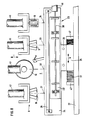
- the optical cable 1 consists of the actual optical waveguide 2 in the form of a glass fiber, which is protected by various coatings.
- An inner jacket 3 is arranged immediately around the optical waveguide, but is usually constructed in two stages and has a so-called wire 4 made of plastic material and a microcoating 5, e.g. made of silicone.
- a fiber jacket 6 made of a bundle of very tough and high-tensile fibers is placed around the inner jacket 3. This fiber jacket serves to relieve the strain on the conductor, but also protects against other mechanical influences, e.g. Beats, kinks, etc.
- the fiber jacket can e.g. made of glass yarn or aramid (e.g. KEVLAR, registered trademark) or a mixture of these materials.
- the fiber jacket is surrounded by an outer jacket 7, which has a comparatively large wall thickness and which is made of plastic material.
- the optical cable shown actually has an outside diameter of approximately 2 to 4 mm, while the outside diameter of the inner jacket 3 is still approximately 0.9 mm.
- the diameter of the optical fiber is less than 0.2mm, which requires extremely careful handling when stripping.
- the outer jacket 7 is first inserted into the fiber jacket with the aid of cutting knives 16 cut and then peeled off. This can be done with a tool that works according to the general principle of stripping pliers, whereby the depth of cut can be adjusted.
- the outer sheath 7 is pulled off coaxially with the optical waveguide in the direction of the arrow d. Either the cutting knives 16 can be moved or the remaining cable could also be withdrawn when the cutting knives are stationary.
- Figure 3 shows the bending of the fiber jacket 6 with the aid of a blowing nozzle 10, which e.g. Compressed air blows against the optical cable 1 at approximately a right angle.
- the fiber cladding can thus be held in a clamping device 11.
- the clamping device has a clamping bearing 13, which acts as an abutment for a clamping element, e.g. serves for a swivel arm 14.
- a separating element such as e.g. a cutting disc 12 is moved in the direction of arrow f against the fiber cladding.
- the cutting disc rotates in the direction of arrow g at a relatively high speed, so that a clean cut is ensured.
- the clamping device 11 and the cutting disc 12 are part of a cutting device 9, which could also have other elements.
- the cutting disc could also approach the fiber jacket from another side.
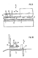
- FIG. 4 shows the inner jacket 3 freed from the outer jacket and from the fiber jacket. Only a short fiber beard is visible from the fiber jacket 6, but this does not interfere with further processing. Now, with the help of the cutting knives 17, the inner jacket 3 is cut down to the microcoating.
- Detaching the inner jacket requires extreme caution and is therefore carried out in a separate operation as shown in FIG. 5.
- the inner jacket 3 which has already been cut is gripped by heating jaws and pulled off in the direction of the arrow h.
- the inner jacket in a single operation is removed with a tool.
- the inner jacket can also be easily removed in the position according to FIG. 3 before the fiber jacket is separated.
- Figure 6 shows the fully stripped cable after going through all the process steps.
- the individual stripping masses a and b and the length c of the remaining fiber beard can be adjusted. This mass is directed e.g. after the optical connectors to be connected to the end portion of the optical cable.
- FIG. 7 shows the overall structure of a device according to the invention in a greatly simplified representation.
- the individual workstations which are explained in more detail in FIG. 8, are set up side by side on a table 19.
- the transport device 23 with the clamps is hung on a yoke 22 above the bearing block 24.
- the individual work stations are arranged linearly along the transport device, each work station being provided with a pneumatic drive element in order to actuate the work tools.
- the transport device is also activated pneumatically, so that obviously a large number of pneumatic control elements 20 are required. These are accommodated under the table surface in an insert 21 and are therefore easily accessible at all times.
- the insert can also accommodate other electrical or electronic control elements.
- a device would also be constructed in a similar manner, in which an end section remains firmly clamped and the individual work stations are guided to the cable.
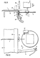
- Figure 8 also shows a simplified simplified top view of the device according to Figure 7.
- the individual work stations are arranged linearly next to one another, with a cutting device 8 being provided on a first work station 31, which has cutting knives 16 for cutting and removing the outer casing.
- the separating device 9 is provided with the separating disk 12 and with the clamping device 11 (not visible here).
- the cutting knives 17 are arranged for cutting the inner jacket and at the fourth work station 34 the movable heating jaws 18 are fastened, with which the cut inner jacket can be removed.
- All work tools at the individual work stations 31 to 34 can be moved along guide rods 43 in the direction of arrow i coaxial to the optical cable.
- the individual end sections are guided past the work stations with a transport device 23, the details of which can also be seen from FIGS. 9 and 10.
- the transport device essentially consists of a conveyor bar 28, which is designed in cross section as an approximately L-shaped profile.
- Clamping pliers are arranged under the conveyor bar, each of which has a fixed jaw 36 and a movable jaw 37.
- the clamping jaws are rounded in a semicircle so that they can grip the optical cables 1.
- the movable clamping jaws 37 are provided with a holder 45 which projects upwards through an opening 44 in the conveyor strip 28. All brackets 45 of the individual clamping pliers are firmly connected to a common push rod 30 which e.g.
- the conveyor bar 28 is suspended on a vertical feed 26 and can be moved up and down on this in the direction of arrow 1 parallel to the bearing bar 24 arranged underneath the.
- the vertical feed 26 is in turn connected to a horizontal feed 25, on which the entire arrangement can be moved back and forth in the direction of arrow n.
- Vertical feed and horizontal feed are preferably also pneumatic drive elements.
- the horizontal feed 25 is attached to the yoke 22, which extends over the entire length of the bearing bar 24.
- a bellows 27 is arranged as a protective device between the fixed side parts 47 on the yoke 22 and the horizontal feed 25.
- an optical cable 1 lying on the bearing bar 24 can be detected, raised and placed on the bearing bar 24 again in a feed cycle at a subsequent work station.
- the clamps are all opened together and the transport bar 28 swings back in a reversing cycle in order to transport all the cables one station further.
- a pneumatically activatable hold-down bar 29 is provided which can be moved up and down plane-parallel to the bearing bar 24 in the direction of arrow m.
- the hold-down bar 29 is pressed downward, so that all the cables inserted in the transport device are clamped onto the bearing bar 24.
- the hold-down bar 29 is raised so that it does not hinder the further transport of the cables.
- FIG. 11 shows the optical cable 1 fixed on the bearing strip 24, over the end section of which the nozzle 10 is arranged.
- the nozzle 10 is preferably a slot nozzle, so that all fibers are blown downwards in a certain area.
- the fiber jacket comes to lie in a clamp bearing 13 which has approximately V-shaped receiving openings.
- the clamp bearing 13 has a holding section 38, in which the fiber jacket can be stretched freely.
- a swivel arm 14 is articulated on the bearing strip 24 and can be swiveled pneumatically in the direction of the arrow o against the clamp bearing 13.
- An additional blowing nozzle 15 is arranged at the free end of the swivel arm 14, so that even slightly protruding fibers are pressed into the clamping bearing 13.
- the cutting disc 12 together with its drive 41 is moved in the direction of the arrow p against the holding section 38.
- a fixed switch 40 is activated, which sets the drive 41 in motion.
- the cutting disc 12 is therefore only set in motion when the fiber jacket is already clamped. This way, no unnecessary turbulence is generated.
- the swivel arm 14 is extended again and the separated fibers are sucked in and removed by a suction nozzle 39. The device thus remains free of contamination.
- the cutting disc 12 is arranged to be height-adjustable in the direction of arrow q.
- the end section is transported on to the subsequent work station 33.
- the stripped end section is ejected by the transport device and can be removed manually.
- Intermediate stations may be arranged between the individual work stations, which either remain empty or at which certain devices such as e.g. Blow nozzles, heaters or spray nozzles can be arranged. The intermediate stations can also be used for visual control.
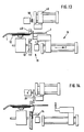
- FIGS. 13 to 16 show, in a highly simplified manner, an alternative exemplary embodiment of a device in which the end sections do not start at different work stations in one transport device.
- the end sections are clamped stationary and the individual work steps are carried out by bringing the individual work tools from a rest position to the end section.
- FIGS. 13 to 15 show side views of the device in various working stages.
- the optical cable 1 is clamped in a stationary clamping point 48 which e.g. can be formed by a clamp.
- the clamping device 11 with the clamping bearing 13 is arranged directly below the clamping point.
- the cutting device 8 is arranged so that it can be displaced axially parallel to the optical waveguide somewhat below the plane of the clamping point 48.
- the cutting disc 12 is arranged opposite the cutting device 8 on the other side of the clamping bearing 13.
- the nozzle 10 can be pivoted in and out in the direction of the arrow s, so that it does not hinder the function of the cutting device 8.
- the cutting device 8 has cut the outer casing 7 and is now pulled back in the direction of the arrow r, so that the outer casing is removed.
- the further separating device 49, the nozzle 10, the cutting disk 12 and the swivel arm of the clamping device 11 are in the rest position.
- the nozzle 10 is pivoted down against the optical cable 1 and activated according to FIG. 14, so that the fiber jacket is blown down onto the clamp bearing 13. Now the clamping device is activated, whereby the swivel arm 14 is pressed against the clamp bearing and clamps the fiber jacket. After the fiber sheath has been clamped, the nozzle 10 can again be pivoted up.
- the inner jacket is first pulled off before the fiber jacket is separated. This sequence is particularly recommended if the remaining fiber beard should be relatively long so that it could hinder the separation of the inner jacket.
- the further separating device 49 is activated according to FIG. 15 by moving its cutting knife downward in the direction of arrow t over the end section. The inner jacket is cut and removed using the same tool, by pulling the knives backwards in the direction of the arrow u. The rear position is shown in FIG. 15 in dash-dotted lines. The cutting device 8 has been withdrawn to such an extent that it does not impair the action of the further separating device 49.
- the cutting disc 12 is moved together with its drive in the direction of the arrow v against the pinched fiber jacket.
- the end section can then be removed again from the clamping point 48.
- the individual work tools can be designed approximately analogously to the previously described embodiment.
- adjustment options can be provided so that the stripping a, b and c can be adjusted according to FIG. 6.
- Guide rods and pneumatic drives are used for the linear displacement of the individual work tools.
- FIG. 17 shows the already mentioned alternative possibility of a separating device 9, which can be used advantageously in place of the separating disk on the devices described above.
- the actual cutting tool consists of the two jaws 50 and 51, which in the present case are designed as prismatic bodies.
- the jaw 51 is wedge-shaped and has a rounded edge 52.
- the jaw 50 has a flat surface 53.
- the two jaws can be pressed against each other in the direction of the arrow x, but only one of the two jaws can be designed to be movable.
- the two jaws can be clamped in a conventional toggle lever pliers, or they can also be part of a device in which the jaws are actuated by a motor.
- the two jaws are machined so precisely that in the closed state, the edge 52 rests on the jaw 50 with absolutely no play and no space.
- An air jet is blown out of the nozzle 10 against the exposed fiber jacket 6 in such a way that it is bent off one side of the cable axis and comes to rest between the two jaws 50 and 51.
- the fiber jacket is held in the correct position with the aid of a clamping device 11, after which the two jaws can close.
- the press force to be applied is approx. 100 - 150 kg.
- Figure 19 shows schematically the variant shown in Figure 17 with a flat jaw.
- the wedge-shaped jaw has a radius r1 of, for example, 0.1 to 0.2 mm.
- the wedge angle ⁇ is preferably chosen to be approximately between 60 ° and 80 °.
- An alternative variant is shown in FIG. 20, in which one jaw has a radius r2 which is greater than the radius r1 of the opposite jaw. According to FIG. 18, both jaws have approximately the same radius r1 and r2.
- the jaws could also be of asymmetrical design in cross section. It would also be conceivable to design the wedge-shaped jaw not as a linear but as a curved body, so that the cutting edge 52 can be rolled off on the lower jaw.
- the wedge-shaped jaw does not have a sharp cutting edge, but a wedge rounding of approx. 0.1 - 0.5 mm radius.
- the wedge angle can be between 40 ° - 90 °.
- the two jaws are particularly advantageously made of hard metal, since this material is particularly wear-resistant. It is also important that the jaws are made of a hard material, otherwise the fibers cannot be severed. Instead of hard metal, other sintered materials or ceramics or hardened steel would also be conceivable.
Landscapes
- Physics & Mathematics (AREA)
- General Physics & Mathematics (AREA)
- Optics & Photonics (AREA)
- Removal Of Insulation Or Armoring From Wires Or Cables (AREA)
- Light Guides In General And Applications Therefor (AREA)
- Manufacturing Of Electrical Connectors (AREA)
- Mechanical Coupling Of Light Guides (AREA)
Applications Claiming Priority (4)
| Application Number | Priority Date | Filing Date | Title |
|---|---|---|---|
| CH4044/89 | 1989-11-09 | ||
| CH404489 | 1989-11-09 | ||
| CH3148/90 | 1990-10-01 | ||
| CH3148/90A CH682434A5 (de) | 1990-10-01 | 1990-10-01 | Verfahren und Vorrichtung zum Trennen des der Zugentlastung dienenden Fasermantels an Kabeln, insbesondere an Glasfaserkabeln. |
Publications (1)
| Publication Number | Publication Date |
|---|---|
| EP0430868A1 true EP0430868A1 (fr) | 1991-06-05 |
Family
ID=25692310
Family Applications (1)
| Application Number | Title | Priority Date | Filing Date |
|---|---|---|---|
| EP90810826A Withdrawn EP0430868A1 (fr) | 1989-11-09 | 1990-10-29 | Procédé et dispositif pour dénuder les extrémités de câbles optiques |
Country Status (4)
| Country | Link |
|---|---|
| EP (1) | EP0430868A1 (fr) |
| JP (1) | JPH03179302A (fr) |
| AU (1) | AU6588190A (fr) |
| CA (1) | CA2028745A1 (fr) |
Cited By (7)
| Publication number | Priority date | Publication date | Assignee | Title |
|---|---|---|---|---|
| GB2261557A (en) * | 1991-11-12 | 1993-05-19 | Jiri Stepan | Cutting fibres in cable sheathing |
| DE19736077A1 (de) * | 1997-08-20 | 1999-03-04 | Bosch Gmbh Robert | Abmantelvorrichtung für ein optisches Kabel |
| DE19941627C1 (de) * | 1999-09-01 | 2001-08-02 | Fraunhofer Ges Forschung | Verfahren und Vorrichtung zum automatischen Entfernen der Seele von an einem Ende abgemantelten mehradrigen Elektrokabeln |
| WO2006128597A1 (fr) * | 2005-05-30 | 2006-12-07 | Rosenberger Hochfrequenztechnik Gmbh & Co. Kg | Procede pour preparer une extremite de cable pour le montage d'un connecteur enfichable |
| WO2010028127A1 (fr) * | 2008-09-03 | 2010-03-11 | Adc Telecommunications, Inc. | Outil de préparation de câble à fibre optique/de cuivre hybride |
| WO2014060883A1 (fr) * | 2012-10-19 | 2014-04-24 | Tyco Electronics (Shanghai) Co. Ltd. | Système et procédé pour dénuder des câbles optiques |
| CN113451946A (zh) * | 2021-08-03 | 2021-09-28 | 广东电网有限责任公司 | 一种全自动电缆接头制作工具 |
Families Citing this family (4)
| Publication number | Priority date | Publication date | Assignee | Title |
|---|---|---|---|---|
| JP2531169Y2 (ja) * | 1991-11-25 | 1997-04-02 | 住友電気工業株式会社 | 被覆線材の被覆除去装置 |
| CN110729622B (zh) * | 2019-10-29 | 2025-03-18 | 捷云智能装备(苏州)有限公司 | 电线外包覆层去除机及其去外包覆层方法 |
| CN112838463B (zh) * | 2021-01-09 | 2022-05-10 | 台州腾标电子有限公司 | 一种线缆脱皮设备 |
| CN115946175B (zh) * | 2023-01-05 | 2026-04-10 | 深圳市比洋光通信科技股份有限公司 | 一种防水尾缆加工工艺及其加工设备 |
Citations (6)
| Publication number | Priority date | Publication date | Assignee | Title |
|---|---|---|---|---|
| US3768143A (en) * | 1971-07-26 | 1973-10-30 | R Holmes | Method and apparatus for stripping electrical cable ends |
| WO1981000374A1 (fr) * | 1979-07-26 | 1981-02-19 | Brasilia Telecom | Outil de coupage et clivage de fibres optiques |
| JPS60108803A (ja) * | 1983-11-18 | 1985-06-14 | Nippon Telegr & Teleph Corp <Ntt> | 光フアイバの端末形成装置 |
| DE3406917A1 (de) * | 1984-02-25 | 1985-09-05 | Philips Patentverwaltung Gmbh, 2000 Hamburg | Vorrichtung zum abloesen der auf die glasfaser von lichtwellenleitern aufgebrachten beschichtung |
| GB2207255A (en) * | 1987-07-18 | 1989-01-25 | Stc Plc | Removing optical fibre encapsulation with hot gas jet |
| DE3735282A1 (de) * | 1987-10-17 | 1989-04-27 | Statomat Globe Maschf | Verfahren und vorrichtung zum abtrennen von kabelfaeden beim abmanteln von kabelenden und vorrichtung zur durchfuehrung des verfahrens |
-
1990
- 1990-10-29 CA CA002028745A patent/CA2028745A1/fr not_active Abandoned
- 1990-10-29 EP EP90810826A patent/EP0430868A1/fr not_active Withdrawn
- 1990-11-08 AU AU65881/90A patent/AU6588190A/en not_active Abandoned
- 1990-11-09 JP JP2305941A patent/JPH03179302A/ja active Pending
Patent Citations (6)
| Publication number | Priority date | Publication date | Assignee | Title |
|---|---|---|---|---|
| US3768143A (en) * | 1971-07-26 | 1973-10-30 | R Holmes | Method and apparatus for stripping electrical cable ends |
| WO1981000374A1 (fr) * | 1979-07-26 | 1981-02-19 | Brasilia Telecom | Outil de coupage et clivage de fibres optiques |
| JPS60108803A (ja) * | 1983-11-18 | 1985-06-14 | Nippon Telegr & Teleph Corp <Ntt> | 光フアイバの端末形成装置 |
| DE3406917A1 (de) * | 1984-02-25 | 1985-09-05 | Philips Patentverwaltung Gmbh, 2000 Hamburg | Vorrichtung zum abloesen der auf die glasfaser von lichtwellenleitern aufgebrachten beschichtung |
| GB2207255A (en) * | 1987-07-18 | 1989-01-25 | Stc Plc | Removing optical fibre encapsulation with hot gas jet |
| DE3735282A1 (de) * | 1987-10-17 | 1989-04-27 | Statomat Globe Maschf | Verfahren und vorrichtung zum abtrennen von kabelfaeden beim abmanteln von kabelenden und vorrichtung zur durchfuehrung des verfahrens |
Non-Patent Citations (2)
| Title |
|---|
| PATENT ABSTRACTS OF JAPAN Band 9, Nr. 259 (P-397)(1982), 17. Oktober 1985; & JP - A - 60108803 (NIPPON DENSHIN DENWA KOSHA) 14.06.1985 * |
| RESEARCH DISCLOSURE 10. Mai 1990, Seite 31367; "Kevlar Fan and Trim Device for Optical Cables" * |
Cited By (13)
| Publication number | Priority date | Publication date | Assignee | Title |
|---|---|---|---|---|
| DE4238774B4 (de) * | 1991-11-12 | 2004-03-04 | Schleuniger Holding Ag | Verfahren und Vorrichtung zum Durchtrennen einer Kabelummantelung aus Fasern |
| CH683655A5 (de) * | 1991-11-12 | 1994-04-15 | Jiri Stepan | Verfahren und Vorrichtung zum Durchtrennen einer Kabelummantelung aus Fasern. |
| US5438753A (en) * | 1991-11-12 | 1995-08-08 | Stepan; Jiri | Process and apparatus for cutting through a cable sheathing of fibres |
| GB2261557B (en) * | 1991-11-12 | 1995-08-23 | Jiri Stepan | Process and apparatus for cutting through a cable sheathing of fibres |
| GB2261557A (en) * | 1991-11-12 | 1993-05-19 | Jiri Stepan | Cutting fibres in cable sheathing |
| DE19736077A1 (de) * | 1997-08-20 | 1999-03-04 | Bosch Gmbh Robert | Abmantelvorrichtung für ein optisches Kabel |
| DE19941627C1 (de) * | 1999-09-01 | 2001-08-02 | Fraunhofer Ges Forschung | Verfahren und Vorrichtung zum automatischen Entfernen der Seele von an einem Ende abgemantelten mehradrigen Elektrokabeln |
| WO2006128597A1 (fr) * | 2005-05-30 | 2006-12-07 | Rosenberger Hochfrequenztechnik Gmbh & Co. Kg | Procede pour preparer une extremite de cable pour le montage d'un connecteur enfichable |
| WO2010028127A1 (fr) * | 2008-09-03 | 2010-03-11 | Adc Telecommunications, Inc. | Outil de préparation de câble à fibre optique/de cuivre hybride |
| US8640329B2 (en) | 2008-09-03 | 2014-02-04 | Adc Telecommunications, Inc. | Hybrid fiber/copper cable preparation tool |
| WO2014060883A1 (fr) * | 2012-10-19 | 2014-04-24 | Tyco Electronics (Shanghai) Co. Ltd. | Système et procédé pour dénuder des câbles optiques |
| CN113451946A (zh) * | 2021-08-03 | 2021-09-28 | 广东电网有限责任公司 | 一种全自动电缆接头制作工具 |
| CN113451946B (zh) * | 2021-08-03 | 2023-01-24 | 广东电网有限责任公司 | 一种全自动电缆接头制作工具 |
Also Published As
| Publication number | Publication date |
|---|---|
| AU6588190A (en) | 1991-05-16 |
| CA2028745A1 (fr) | 1991-05-10 |
| JPH03179302A (ja) | 1991-08-05 |
Similar Documents
| Publication | Publication Date | Title |
|---|---|---|
| EP1670109B1 (fr) | Dispositif de dénudage | |
| DE3779945T2 (de) | Drahtabisolierapparat und automatische verdrahtungsvorrichtung die diesen aufnimmt. | |
| DE69009368T2 (de) | Vorrichtung und Verfahren zur Drahtbearbeitung. | |
| DE3922437A1 (de) | Drahtbearbeitungsvorrichtung | |
| DE4238774B4 (de) | Verfahren und Vorrichtung zum Durchtrennen einer Kabelummantelung aus Fasern | |
| CH683645A5 (de) | Abisoliervorrichtung für Glasfaserkabel. | |
| EP0430868A1 (fr) | Procédé et dispositif pour dénuder les extrémités de câbles optiques | |
| EP2897744A1 (fr) | Dispositif et procédé de torsadage automatique de fils métalliques, en particulier pour l'assemblage d'éléments de structure adjacents, de préférence entrecroisés | |
| EP0143960A2 (fr) | Dispositif pour le redressage et la coupe à longueur de matériau en forme de fils | |
| DE19752452A1 (de) | Drahtschneid- und Abisoliermechanismus | |
| CH681339A5 (fr) | ||
| EP1070374B1 (fr) | Dispositif et procede de denudage | |
| DE102016109155B3 (de) | Verdrillanlage, Tandem-Verdrillanlage und Verfahren zum Bestücken eines Verdrillkopfs | |
| EP1356326B1 (fr) | Outil en forme de pince et procede permettant de sectionner des cables a fibres optiques | |
| EP1147440B1 (fr) | Dispositif pour sectionner au moins une fibre optique | |
| DE2014146B2 (de) | Verfahren und Vorrichtung zum Andrücken elektrischer Verbinder | |
| DE3902697C2 (de) | Verfahren und Vorrichtung zum Abmanteln von isolierten Leitungen, insbesondere abgeschirmten Koaxialleitungen | |
| DE3836498A1 (de) | Verfahren und vorrichtung zum entfernen eines um eine platte fuer gedruckte schaltungen gewickelten klebebandes | |
| DE10212993B4 (de) | Crimp-Verfahren | |
| WO2004036277A1 (fr) | Procede et dispositif pour episser des guides d'onde optique par fusion | |
| DE3338096A1 (de) | Verfahren und vorrichtung zum ablaengen von metallenen langformguetern | |
| DE10209181B4 (de) | Verfahren und Zange zum Abisolieren von Leiterenden | |
| DE3925850A1 (de) | Verfahren zum absetzen von kabeln, insbesondere von lichtwellenleiterkabeln | |
| CH665983A5 (en) | Contact attacher for cable - press fits contact element after removal of insulation from appropriate length of cable end gripped between jaws under programmed control | |
| EP0774677A2 (fr) | Dispositif pour enlever la gaine de protection d'une fibre optique |
Legal Events
| Date | Code | Title | Description |
|---|---|---|---|
| PUAI | Public reference made under article 153(3) epc to a published international application that has entered the european phase |
Free format text: ORIGINAL CODE: 0009012 |
|
| AK | Designated contracting states |
Kind code of ref document: A1 Designated state(s): AT BE CH DE DK ES FR GB GR IT LI LU NL SE |
|
| STAA | Information on the status of an ep patent application or granted ep patent |
Free format text: STATUS: THE APPLICATION IS DEEMED TO BE WITHDRAWN |
|
| 18D | Application deemed to be withdrawn |
Effective date: 19911206 |