EP0430912A2 - Golfclubstiel mit niedrigem Biegungspunkt - Google Patents
Golfclubstiel mit niedrigem Biegungspunkt Download PDFInfo
- Publication number
- EP0430912A2 EP0430912A2 EP90850344A EP90850344A EP0430912A2 EP 0430912 A2 EP0430912 A2 EP 0430912A2 EP 90850344 A EP90850344 A EP 90850344A EP 90850344 A EP90850344 A EP 90850344A EP 0430912 A2 EP0430912 A2 EP 0430912A2
- Authority
- EP
- European Patent Office
- Prior art keywords
- shaft
- section
- length
- butt
- tip
- Prior art date
- Legal status (The legal status is an assumption and is not a legal conclusion. Google has not performed a legal analysis and makes no representation as to the accuracy of the status listed.)
- Granted
Links
- 239000002023 wood Substances 0.000 claims abstract description 22
- 229910052751 metal Inorganic materials 0.000 claims description 4
- 239000002184 metal Substances 0.000 claims description 4
- 230000003068 static effect Effects 0.000 description 12
- 238000012360 testing method Methods 0.000 description 6
- 230000008859 change Effects 0.000 description 4
- 238000000034 method Methods 0.000 description 4
- 230000008901 benefit Effects 0.000 description 3
- RTAQQCXQSZGOHL-UHFFFAOYSA-N Titanium Chemical compound [Ti] RTAQQCXQSZGOHL-UHFFFAOYSA-N 0.000 description 2
- 238000005259 measurement Methods 0.000 description 2
- 239000010936 titanium Substances 0.000 description 2
- 229910052719 titanium Inorganic materials 0.000 description 2
- 229910000831 Steel Inorganic materials 0.000 description 1
- 230000009471 action Effects 0.000 description 1
- 238000007792 addition Methods 0.000 description 1
- 238000012217 deletion Methods 0.000 description 1
- 230000037430 deletion Effects 0.000 description 1
- 230000001747 exhibiting effect Effects 0.000 description 1
- 238000004519 manufacturing process Methods 0.000 description 1
- 238000012986 modification Methods 0.000 description 1
- 230000004048 modification Effects 0.000 description 1
- 230000008569 process Effects 0.000 description 1
- 239000010959 steel Substances 0.000 description 1
- 238000006467 substitution reaction Methods 0.000 description 1
- 230000003313 weakening effect Effects 0.000 description 1
Images



Classifications
-
- A—HUMAN NECESSITIES
- A63—SPORTS; GAMES; AMUSEMENTS
- A63B—APPARATUS FOR PHYSICAL TRAINING, GYMNASTICS, SWIMMING, CLIMBING, OR FENCING; BALL GAMES; TRAINING EQUIPMENT
- A63B53/00—Golf clubs
- A63B53/12—Metallic shafts
-
- A—HUMAN NECESSITIES
- A63—SPORTS; GAMES; AMUSEMENTS
- A63B—APPARATUS FOR PHYSICAL TRAINING, GYMNASTICS, SWIMMING, CLIMBING, OR FENCING; BALL GAMES; TRAINING EQUIPMENT
- A63B60/00—Details or accessories of golf clubs, bats, rackets or the like
-
- A—HUMAN NECESSITIES
- A63—SPORTS; GAMES; AMUSEMENTS
- A63B—APPARATUS FOR PHYSICAL TRAINING, GYMNASTICS, SWIMMING, CLIMBING, OR FENCING; BALL GAMES; TRAINING EQUIPMENT
- A63B60/00—Details or accessories of golf clubs, bats, rackets or the like
- A63B60/06—Handles
-
- A—HUMAN NECESSITIES
- A63—SPORTS; GAMES; AMUSEMENTS
- A63B—APPARATUS FOR PHYSICAL TRAINING, GYMNASTICS, SWIMMING, CLIMBING, OR FENCING; BALL GAMES; TRAINING EQUIPMENT
- A63B60/00—Details or accessories of golf clubs, bats, rackets or the like
- A63B60/06—Handles
- A63B60/08—Handles characterised by the material
-
- A—HUMAN NECESSITIES
- A63—SPORTS; GAMES; AMUSEMENTS
- A63B—APPARATUS FOR PHYSICAL TRAINING, GYMNASTICS, SWIMMING, CLIMBING, OR FENCING; BALL GAMES; TRAINING EQUIPMENT
- A63B60/00—Details or accessories of golf clubs, bats, rackets or the like
- A63B60/06—Handles
- A63B60/10—Handles with means for indicating correct holding positions
Definitions
- the present invention relates to wood golf club shafts, i.e., shafts which are adapted to receive a wood club head, and especially to a wood golf club shaft exhibiting a slow kick point.
- a common characteristic of golf club shafts, especially wood golf club shafts, in the process of being played is a tendency for the shaft to flex or bend backwardly during the downstroke. Consequently, the amount of momentum and directional control imparted to the ball is enhanced. Accordingly, many golf club shafts have been designed to promote such a flexing action.
- the point along the shaft about which a maximum flexing occurs has various names, such as "kick point”, "flex point” and “whip point” for example.
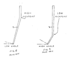
- Shafts have been designed with a so-called high kick point located nearer to the butt of the shaft, a low kick point located nearer to the tip, and a middle kick point located at or near the shaft midpoint.
- the location of the kick point along the shaft influences shaft playability by affecting the angle of the shaft at the moment of contact with the ball. That is, the lower the location of the kick point, the greater the angle of trajectory of the ball, i.e., the higher the ball travels.
- a shaft also exhibits a certain "feel" to a golfer which is a function of the overall flexibility of the shaft. Flexibility of the shaft can be determined by measuring a static flex characteristic of the shaft.
- That shaft is formed of metal such as titanium and includes a gradually tapered section 1 which interconnects butt and tip sections 2, 3 of the shaft.
- the butt section has a standard outer diameter d1 of 0.6 in.
- the tip section has a standard outer diameter d2 of 0.335 in.
- the total shaft length L′ is a standard 45 in.
- the tapered section 1 tapers down from the butt section 2 to the tip section 3 at a rate of 0.011 in./in. (i.e., the outer diameter changes by 0.011 in. per in. of length).
- the tapered section has a length L1′ of 24.5 in., and the section of the shaft wall forming the taper gradually increases toward the tip section from a minimum thickness t1 of .018 in. to a maximum thickness t2 of 0.03 in.
- the tapered section is formed by two successive swaging operations.
- the butt section length L2′ is 15.5 in. and the tip section length L3′ is in.
- the static flex of the shaft is 5.94 in.
- the kick point of the shaft is located at a distance 54′ of 28.75 in. sfrom the butt end of the shaft. (The manner of measuring the flexure and the location of the kick point will be described hereinafter.)
- the butt section length L2′ is 16.125 in. and the tip section length L3′ is 4.375 in.
- the kick point of the shaft is located a distance L4′ of 28.0 in. from the butt end of the shaft.
- the static flex of that shaft is 5.6 in. reflecting a greater stiffness than the earlier described embodiment.
- a kick point of a wood club shaft it may be desired to change the location of a kick point of a wood club shaft in order to appeal to golfers whose style of play would benefit from such a change.
- This can be achieved by changing the relative strength of the butt and tip sections 2, 3 of the shaft.
- the tip section of the shaft would be weakened relative to the butt section, or the butt section would be strengthened relative to the tip section.
- the former patent explains how a kick point or whip point can be established by creating a step in the shaft, i.e., by reducing the diameter of the shaft at a suitable location.
- This reduced diameter portion lies between upper and lower shaft portions of greater diameter.
- Such a shaft structure is difficult to manufacture and is prone to breakage at the reduced diameter portion which serves to weaken the shaft. Furthermorel the static flex characteristic of the shaft is changed so that the club no longer has the same "feel" to the golfer.
- the present invention relates to a low kick point wood golf club shaft adapted to receive a wood head.
- the shaft is about 44 to 45 in. in total length from a butt end to a tip end thereof and comprises a butt section, a tip section, and a tapered section interconnecting the butt and tip sections.
- the butt section has an outer diameter of about 0.6 in., the tip having an outer diameter of about 0.335 in.
- the tapered section tapers down toward the tip section at a rate in the range of about 0.018 to 0.025 in./in.
- the tapered section has a length which is shorter than a length of the butt section, longer than a length of the tip section, and no longer than about 13 in.
- the shaft kick point is disposed at a distance of at least about 29 in. from the butt end.
- the tapered section length is in a range of about 11.5 to 13.5 in., most preferably about 12.75 in.
- the taper rate of the tapered section is most preferably about 0.021 in./in.
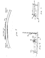
- a wood golf club shaft 10 according to the present invention is formed of metal, such as titanium, and comprises butt and tip sections 12, 14 interconnected by a gradually tapered section 16.
- the butt portion 12 is cylindrical and adapted to receive a conventional grip.
- the tip section 14 is also cylindrical and adapted to receive a wood club head 18 shown in phantom.
- the overall length L of the shaft is 45 in.
- the butt section has an outer diameter 01 of 0.6 in., and the tip section has an outer diameter D2 of 0.335 in.
- the wall thickness T1 of the butt section 12 is .017-.018 in. and the wall thickness T2 of the tip section 14 is .029-.030 in.
- the tapered section 16 has a length L1 which is appreciably shorter than the butt section length L2 and appreciably longer than the tip section length L3.
- the tapered section length L1 is not longer than 13 in. and is preferably in a range of about 12.5 to 13 in.
- the butt section length L2 is preferably in a range of about 21 to 23 in., more preferably in a range of about 22 to 22.75 in.
- the tip section length is preferably in a range of about 9 to 11 in. and more preferably about 9.25 to 10.25 in.
- the tapered section 16 tapers down toward the tip section at a rate in a range of about 0.018 to 0.025 in./in., preferably about 0.020 to 0.023 in./in., and most preferably about 0.021 in./in.
- the kick point KP of the shaft is located at a distance L4 of at least about 29 in. from the butt end 20 of the shaft.
- the kick point location of the shaft is measured by the following procedure.
- the shaft 10 is placed in a test fixture 22 (FIGS. 2-4) which includes a pair of yoke-shaped support guides 24. Those guides permit the shaft to move in only a vertical direction.
- a steel mandrel 26 abuts against the tip end 28 of the shaft and is held stationary in any suitable manner.
- the butt end 20 of the shaft rests against a plate 30 which is attached to a movable rod 32 which may, for example, comprise a threaded rod arranged in a turnbuckle (not shown) which enables the rod to be displaced toward the shaft 10.
- a movable rod 32 which may, for example, comprise a threaded rod arranged in a turnbuckle (not shown) which enables the rod to be displaced toward the shaft 10.
- the rod is displaced by a distance R of 0.75 in.
- a 150 watt spotlight 34 (FIG. 4) is disposed at a distance M of 51 inches from the shaft axis at the same elevation as the shaft axis when the shaft is in a non-buckled state (FIG. 2).
- the light 34 is actuated to cause the shaft 10 to cast a shadow SH onto a sheet of grid paper 36 situated at a distance E′ of three inches from the shaft axis.
- the kick point KP is taken as the point on the grid paper representing the maximum deflection of the shaft, i.e., the highest point of the shadow on the grid paper (see FIG. 5). That point occurs where the slope of the shaft becomes positive.
- the presence of the grid paper makes it easier to measure the distance to the kick point from the butt end of the shaft.
- the use of grid paper is not absolutely necessary, but rather is used to facilitate measurements.
- the static flex of the shaft 10 is measured in a separate fixture 38 (see FIG. 6) in which the butt section of the shaft is clamped by a clamp 40 over the end-most 5.75 in. of the length of the butt section.
- a weight 42 of 6.25 lbs. is hung from the tip section of the shaft at a distance of 0.625 in. from the tip end 28. This causes the shaft to bend.
- a spotlight spaced 76 in. from the shaft in a direction perpendicular to the paper is then turned on to cause the bent shaft to cast a shadow onto grid paper (not shown) located at 2 in. behind the shaft, in a manner similar to that described earlier in connection with the fixture 22.
- the spotlight is disposed at the same elevation as the shaft axis before the shaft is bent.
- the tapered section 16 tapers at a rate of 0.021 in./in.
- the kick point KP is located at a distance L4′ of 29.75 in. from the butt end 20 of the shaft.
- the static flex G of the shaft is 5.94 in. That shaft has a somewhat lower kick point than the previously described first version of the conventional shaft B described in connection with FIG. 7 (i.e., 29.75 in. versus 28.75 in.)1 but has the same static flex of 5.94 in.
- the shaft 10 exhibits the same feel to the user, while imparting a higher elevation to the ball.
- the kick point is located 29 in. from the butt end, and the static flex is 5.6 in.
- This shaft thus has a somewhat lower kick point than the previously described second version of the conventional shaft according to FIG. 7 (i.e., 29 in. versus 28 in.), but has the same static flex of 5.6 in.
- this stiffer version of the shaft 10 exhibits the same feel, while imparting a higher elevation to the ball.
- the length and gradual rate of taper of the tapering section enables the kick point of a wood golf club shaft to be changed while enabling the same feel of the shaft to be more easily maintained.
- the tapering section length is in a range which can be easily produced by a single swaging operation.
Landscapes
- Health & Medical Sciences (AREA)
- General Health & Medical Sciences (AREA)
- Physical Education & Sports Medicine (AREA)
- Golf Clubs (AREA)
Applications Claiming Priority (2)
| Application Number | Priority Date | Filing Date | Title |
|---|---|---|---|
| US433855 | 1989-11-09 | ||
| US07/433,855 US5018735A (en) | 1989-11-09 | 1989-11-09 | Low kick point golf club shaft |
Publications (3)
| Publication Number | Publication Date |
|---|---|
| EP0430912A2 true EP0430912A2 (de) | 1991-06-05 |
| EP0430912A3 EP0430912A3 (en) | 1991-10-23 |
| EP0430912B1 EP0430912B1 (de) | 1994-10-19 |
Family
ID=23721802
Family Applications (1)
| Application Number | Title | Priority Date | Filing Date |
|---|---|---|---|
| EP90850344A Expired - Lifetime EP0430912B1 (de) | 1989-11-09 | 1990-10-17 | Golfclubstiel mit niedrigem Biegungspunkt |
Country Status (5)
| Country | Link |
|---|---|
| US (1) | US5018735A (de) |
| EP (1) | EP0430912B1 (de) |
| JP (1) | JP2561751B2 (de) |
| AT (1) | ATE112975T1 (de) |
| DE (1) | DE69013468D1 (de) |
Cited By (1)
| Publication number | Priority date | Publication date | Assignee | Title |
|---|---|---|---|---|
| US5414987A (en) * | 1991-07-17 | 1995-05-16 | E. I. Du Pont De Nemours And Company | Pre-stuffer box conditioning of ply-twisted carpet yarn |
Families Citing this family (41)
| Publication number | Priority date | Publication date | Assignee | Title |
|---|---|---|---|---|
| US5429008A (en) * | 1992-02-28 | 1995-07-04 | Fujikura Rubber Ltd. | Method and apparatus for measuring figure of deflection of golf club shaft |
| JP2580437B2 (ja) * | 1992-05-26 | 1997-02-12 | ソマール株式会社 | ゴルフクラブ及びゴルフクラブセット |
| JP2576013B2 (ja) * | 1993-03-31 | 1997-01-29 | ソマール株式会社 | ゴルフクラブ及びゴルフクラブセット |
| US5692970A (en) * | 1994-02-09 | 1997-12-02 | Radius Engineering | Composite golf club shaft |
| US6143236A (en) * | 1994-02-09 | 2000-11-07 | Radius Engineering, Inc. | Method for manufacturing composite shafts with injection molded, rigidized bladder with varying wall thickness |
| US5569098A (en) * | 1994-12-15 | 1996-10-29 | New Vision Golf Corp. | Golf putter having tapered shaft and large grip |
| TW361279U (en) * | 1995-01-31 | 1999-06-11 | Wilson Sporting Goods Co Ltd | Shaft for a golf club, set of golf clubs and method of selecting shafts |
| US5551691A (en) * | 1995-06-07 | 1996-09-03 | Somar Corporation | Golf club shaft |
| US5685783A (en) * | 1995-07-27 | 1997-11-11 | Somar Corporation | Golf club shaft |
| US5620380A (en) * | 1995-12-08 | 1997-04-15 | Unifiber Corporation | Light weight golf club shaft having controllable "feel" |
| JPH09206413A (ja) * | 1996-01-31 | 1997-08-12 | Daiwa Seiko Inc | ゴルフクラブシャフト |
| US5904627A (en) * | 1996-05-01 | 1999-05-18 | Kasco Corporation | Golf club shaft |
| US5989133A (en) * | 1996-05-03 | 1999-11-23 | True Temper Sports, Inc. | Golf club and shaft therefor and method of making same |
| US5788585A (en) * | 1996-09-06 | 1998-08-04 | Jackson; Al | Composite golf club shaft and method for its manufacture |
| US5681226A (en) * | 1996-06-03 | 1997-10-28 | Marshall James, Inc. | Golf club shaft with oversized grip section |
| US6117021A (en) | 1996-06-28 | 2000-09-12 | Cobra Golf, Incorporated | Golf club shaft |
| USD418566S (en) * | 1997-07-08 | 2000-01-04 | Cobra Golf Incorporated | Lower section of a shaft adapted for use in a golf club shaft |
| US5935017A (en) * | 1996-06-28 | 1999-08-10 | Cobra Golf Incorporated | Golf club shaft |
| EP1007163A1 (de) * | 1996-11-28 | 2000-06-14 | Wavex Corporation | Golfschlägerschaft mit einem wellenförmigen verstärkungsteil |
| US5820480A (en) * | 1997-01-22 | 1998-10-13 | Harrison Sports Inc. | Golf club shaft and method of making the same |
| US5964670A (en) * | 1997-01-22 | 1999-10-12 | Harrison Sports, Inc. | Golf club shaft having improved feel |
| US6827656B1 (en) * | 1997-01-24 | 2004-12-07 | Hd Golf Development, Inc. | Higher overall flex golf shaft |
| US6340509B1 (en) * | 1997-04-23 | 2002-01-22 | Radius Engineering, Inc. | Composite bicycle frame and method of construction thereof |
| US5865684A (en) * | 1997-05-01 | 1999-02-02 | La Jolla Club, Inc. | Multi-use golf club |
| JP3117934B2 (ja) * | 1997-05-06 | 2000-12-18 | 住友ゴム工業株式会社 | ゴルフクラブシャフト |
| US6309309B1 (en) * | 1997-05-09 | 2001-10-30 | Taylor Made Golf Company, Inc | Oversized iron-type golf club |
| US6582320B2 (en) * | 1997-06-06 | 2003-06-24 | Edwin B. Fendel | Hybrid golf club shaft |
| US5813922A (en) * | 1997-10-15 | 1998-09-29 | Taylor Made Golf Company, Inc. | Golf club shaft |
| US6024651A (en) * | 1997-10-17 | 2000-02-15 | Harrison Sports, Inc. | Golf club shaft having contoured grip section and kick section |
| JP4142181B2 (ja) * | 1997-11-26 | 2008-08-27 | 三菱レイヨン株式会社 | ゴルフクラブ用シャフト |
| US6361451B1 (en) | 1998-09-21 | 2002-03-26 | Mide Technology Corporation | Variable stiffness shaft |
| US6540623B2 (en) | 2000-09-14 | 2003-04-01 | Al Jackson | Composite shaft for a golf club |
| WO2006083122A1 (en) * | 2005-02-03 | 2006-08-10 | Stulz Golf Technologies, Llc | Golf club shaft and method of fabricating the same |
| US20070049393A1 (en) * | 2005-08-26 | 2007-03-01 | Acushnet Company | Method for predicting ball launch conditions |
| US20090143161A1 (en) * | 2007-12-03 | 2009-06-04 | Qualizza Gregory K | Shaft Structure with Configurable Bending, Weight, Moment-of-Inertia and Torque Profile |
| US20150297963A1 (en) * | 2012-08-31 | 2015-10-22 | Mitsubishi Rayon Co., Ltd. | Golf club shaft |
| WO2015006589A1 (en) * | 2013-07-12 | 2015-01-15 | Karsten Manufacturing Corporation | Golf clubs and shafts configured for consistent club gapping |
| WO2018081723A1 (en) * | 2016-10-28 | 2018-05-03 | Karsten Manufacturing Corporation | Diameter profiled golf club shaft to reduce drag |
| US10857433B2 (en) | 2018-01-31 | 2020-12-08 | Breakthrough Golf Technology, Llc | Golf shaft system and golf shaft |
| US10213666B1 (en) | 2018-01-31 | 2019-02-26 | Breakthrough Golf Technology Llc | Golf shaft |
| JP2023546132A (ja) * | 2020-10-15 | 2023-11-01 | トゥルー テンパー スポーツ インコーポレイテッド | 中間部分のテーパ率が複数通りあるステップレスゴルフシャフト |
Family Cites Families (29)
| Publication number | Priority date | Publication date | Assignee | Title |
|---|---|---|---|---|
| USRE19731E (en) * | 1935-10-22 | Tubular metallic shaft | ||
| US976267A (en) * | 1909-03-27 | 1910-11-22 | Arthur F Knight | Golf-club. |
| US1662712A (en) * | 1927-08-01 | 1928-03-13 | James K Thomson | Golf club |
| US1670531A (en) * | 1927-08-17 | 1928-05-22 | American Fork & Hoe Co | Golf shaft |
| US1974389A (en) * | 1930-10-03 | 1934-09-18 | American Fork & Hoe Co | Golf shaft |
| US2037636A (en) * | 1932-03-28 | 1936-04-14 | Horton Mfg Co Inc | Stepped shaft and method of making the same |
| US2250428A (en) * | 1933-10-17 | 1941-07-22 | American Fork & Hoe Co | Golf shaft |
| US2066962A (en) * | 1934-04-16 | 1937-01-05 | Cross Lloyd | Shaft for golf clubs or the like |
| US2124534A (en) * | 1934-07-16 | 1938-07-26 | George E Barnhart | Golf club |
| US2050554A (en) * | 1934-10-30 | 1936-08-11 | George E Barnhart | Golf club shaft |
| GB465415A (en) * | 1935-11-05 | 1937-05-05 | Norman Pearl Vickery | Golf clubs |
| US2153550A (en) * | 1937-01-28 | 1939-04-11 | American Fork & Hoe Co | Golf shaft |
| US2457177A (en) * | 1944-10-17 | 1948-12-28 | Milton B Reach | Golf club |
| US2934345A (en) * | 1957-04-23 | 1960-04-26 | Columbia Products Co | Golf stick and shaft |
| US3083969A (en) * | 1961-03-27 | 1963-04-02 | Axaline Golf Company | Long-handled, swingable driving instrument |
| US3519270A (en) * | 1968-03-04 | 1970-07-07 | John W Baymiller | Flexible shaft putter |
| GB1286255A (en) * | 1968-10-04 | 1972-08-23 | Dunlop Holdings Ltd | Matched sets of golf clubs |
| US3809403A (en) * | 1969-01-13 | 1974-05-07 | C Hunter | Shaft for conventional golf club |
| US4125260A (en) * | 1976-05-17 | 1978-11-14 | True Temper Corporation | Tubular golf shaft of stainless steel |
| JPS5347132A (en) * | 1976-10-13 | 1978-04-27 | Hitachi Construction Machinery | Control method of facing stability of tunnel excavator |
| US4123055A (en) * | 1977-01-03 | 1978-10-31 | Brill Harry M | Golf clubs |
| US4169595A (en) * | 1977-01-19 | 1979-10-02 | Brunswick Corporation | Light weight golf club shaft |
| US4319750A (en) * | 1979-04-30 | 1982-03-16 | Aldila, Inc. | Golf shaft having controlled flex zone |
| GB2053004A (en) * | 1979-06-21 | 1981-02-04 | Accles & Pollock Ltd | Golf club shafts |
| GB2071504B (en) * | 1980-03-13 | 1984-02-15 | Accles & Pollock Ltd | Golf club shafts |
| AU541132B2 (en) * | 1980-03-13 | 1984-12-20 | T.I. Accles & Pollock Ltd | Golf club shaft |
| US4558863A (en) * | 1981-01-02 | 1985-12-17 | Acushnet Company | Golf club shaft |
| US4431187A (en) * | 1982-06-25 | 1984-02-14 | Brunswick Corporation | Golf club shaft |
| JPS62164482A (ja) * | 1986-01-17 | 1987-07-21 | ソマ−ル株式会社 | ゴルフクラブ用シヤフト |
-
1989
- 1989-11-09 US US07/433,855 patent/US5018735A/en not_active Expired - Fee Related
-
1990
- 1990-10-17 AT AT90850344T patent/ATE112975T1/de active
- 1990-10-17 EP EP90850344A patent/EP0430912B1/de not_active Expired - Lifetime
- 1990-10-17 DE DE69013468T patent/DE69013468D1/de not_active Expired - Lifetime
- 1990-11-09 JP JP2302839A patent/JP2561751B2/ja not_active Expired - Lifetime
Cited By (1)
| Publication number | Priority date | Publication date | Assignee | Title |
|---|---|---|---|---|
| US5414987A (en) * | 1991-07-17 | 1995-05-16 | E. I. Du Pont De Nemours And Company | Pre-stuffer box conditioning of ply-twisted carpet yarn |
Also Published As
| Publication number | Publication date |
|---|---|
| US5018735A (en) | 1991-05-28 |
| JPH03176085A (ja) | 1991-07-31 |
| DE69013468D1 (de) | 1994-11-24 |
| ATE112975T1 (de) | 1994-11-15 |
| EP0430912B1 (de) | 1994-10-19 |
| EP0430912A3 (en) | 1991-10-23 |
| JP2561751B2 (ja) | 1996-12-11 |
Similar Documents
| Publication | Publication Date | Title |
|---|---|---|
| US5018735A (en) | Low kick point golf club shaft | |
| US6287215B1 (en) | Golf putter with adjustable lie and loft angles | |
| US5772525A (en) | Golf putter | |
| KR100591963B1 (ko) | 로프트 및 라이 조절용 노치를 구비하는 골프 클럽 헤드 | |
| US4431187A (en) | Golf club shaft | |
| KR20010021056A (ko) | 중량 조절용 부재를 구비하는 아이언형 골프 클럽 헤드 | |
| USRE33735E (en) | Golf club shaft | |
| US5971865A (en) | Golf club with oversize shaft | |
| GB1596431A (en) | Golf clubs | |
| US5259617A (en) | Golf club having swivel facilitating means | |
| JP3117934B2 (ja) | ゴルフクラブシャフト | |
| US5192073A (en) | Golf club set | |
| US20020107089A1 (en) | Golf club shaft formed from metal-containing prepreg and non-metal fiber prepreg and method of making the same | |
| JP3053859U (ja) | 特大アイアン型ゴルフクラブ | |
| KR101645438B1 (ko) | 골프용 퍼터 헤드 및 이를 포함하는 골프용 퍼터 | |
| US20050009620A1 (en) | Golf club shaft with adjustable flex | |
| WO1981000056A1 (en) | Golf club | |
| US6134937A (en) | Golf club and shaft therefor and method of making same | |
| GB2227418A (en) | A golf set | |
| US5935017A (en) | Golf club shaft | |
| US5865688A (en) | Golf club shaft having multiple flex points | |
| EP0351823A1 (de) | Schläger | |
| US6565450B1 (en) | Golf club set | |
| JP7751513B2 (ja) | パタークラブ用シャフト、及び、パタークラブ | |
| AU660089B2 (en) | Golf club |
Legal Events
| Date | Code | Title | Description |
|---|---|---|---|
| PUAI | Public reference made under article 153(3) epc to a published international application that has entered the european phase |
Free format text: ORIGINAL CODE: 0009012 |
|
| AK | Designated contracting states |
Kind code of ref document: A2 Designated state(s): AT BE DE FR GB IT SE |
|
| PUAL | Search report despatched |
Free format text: ORIGINAL CODE: 0009013 |
|
| AK | Designated contracting states |
Kind code of ref document: A3 Designated state(s): AT BE DE FR GB IT SE |
|
| 17P | Request for examination filed |
Effective date: 19911106 |
|
| 17Q | First examination report despatched |
Effective date: 19930326 |
|
| GRAA | (expected) grant |
Free format text: ORIGINAL CODE: 0009210 |
|
| AK | Designated contracting states |
Kind code of ref document: B1 Designated state(s): AT BE DE FR GB IT SE |
|
| PG25 | Lapsed in a contracting state [announced via postgrant information from national office to epo] |
Ref country code: AT Effective date: 19941019 Ref country code: BE Effective date: 19941019 Ref country code: IT Free format text: LAPSE BECAUSE OF FAILURE TO SUBMIT A TRANSLATION OF THE DESCRIPTION OR TO PAY THE FEE WITHIN THE PRE;WARNING: LAPSES OF ITALIAN PATENTS WITH EFFECTIVE DATE BEFORE 2007 MAY HAVE OCCURRED AT ANY TIME BEFORE 2007. THE CORRECT EFFECTIVE DATE MAY BE DIFFERENT FROM THE ONE RECORDED.SCRIBED TIME-LIMIT Effective date: 19941019 |
|
| REF | Corresponds to: |
Ref document number: 112975 Country of ref document: AT Date of ref document: 19941115 Kind code of ref document: T |
|
| REF | Corresponds to: |
Ref document number: 69013468 Country of ref document: DE Date of ref document: 19941124 |
|
| PG25 | Lapsed in a contracting state [announced via postgrant information from national office to epo] |
Ref country code: SE Effective date: 19950119 |
|
| PG25 | Lapsed in a contracting state [announced via postgrant information from national office to epo] |
Ref country code: DE Effective date: 19950120 |
|
| ET | Fr: translation filed | ||
| PLBE | No opposition filed within time limit |
Free format text: ORIGINAL CODE: 0009261 |
|
| STAA | Information on the status of an ep patent application or granted ep patent |
Free format text: STATUS: NO OPPOSITION FILED WITHIN TIME LIMIT |
|
| 26N | No opposition filed | ||
| PGFP | Annual fee paid to national office [announced via postgrant information from national office to epo] |
Ref country code: GB Payment date: 19971008 Year of fee payment: 8 |
|
| PGFP | Annual fee paid to national office [announced via postgrant information from national office to epo] |
Ref country code: FR Payment date: 19971009 Year of fee payment: 8 |
|
| PG25 | Lapsed in a contracting state [announced via postgrant information from national office to epo] |
Ref country code: GB Free format text: LAPSE BECAUSE OF NON-PAYMENT OF DUE FEES Effective date: 19981017 |
|
| GBPC | Gb: european patent ceased through non-payment of renewal fee |
Effective date: 19981017 |
|
| PG25 | Lapsed in a contracting state [announced via postgrant information from national office to epo] |
Ref country code: FR Free format text: LAPSE BECAUSE OF NON-PAYMENT OF DUE FEES Effective date: 19990630 |
|
| REG | Reference to a national code |
Ref country code: FR Ref legal event code: ST |