EP0430955B1 - Kommunikationssystem - Google Patents
Kommunikationssystem Download PDFInfo
- Publication number
- EP0430955B1 EP0430955B1 EP89907717A EP89907717A EP0430955B1 EP 0430955 B1 EP0430955 B1 EP 0430955B1 EP 89907717 A EP89907717 A EP 89907717A EP 89907717 A EP89907717 A EP 89907717A EP 0430955 B1 EP0430955 B1 EP 0430955B1
- Authority
- EP
- European Patent Office
- Prior art keywords
- cell
- register
- substation
- main station
- communication system
- Prior art date
- Legal status (The legal status is an assumption and is not a legal conclusion. Google has not performed a legal analysis and makes no representation as to the accuracy of the status listed.)
- Expired - Lifetime
Links
- 238000004891 communication Methods 0.000 title claims description 37
- 230000011664 signaling Effects 0.000 claims abstract description 109
- 230000005540 biological transmission Effects 0.000 claims abstract description 42
- 238000000034 method Methods 0.000 claims abstract description 11
- 230000000306 recurrent effect Effects 0.000 claims abstract description 3
- 238000001514 detection method Methods 0.000 claims description 16
- 238000011144 upstream manufacturing Methods 0.000 description 11
- 238000011084 recovery Methods 0.000 description 10
- 101100023124 Schizosaccharomyces pombe (strain 972 / ATCC 24843) mfr2 gene Proteins 0.000 description 9
- 238000012545 processing Methods 0.000 description 9
- 101001096074 Homo sapiens Regenerating islet-derived protein 4 Proteins 0.000 description 7
- 102100037889 Regenerating islet-derived protein 4 Human genes 0.000 description 7
- 102100023882 Endoribonuclease ZC3H12A Human genes 0.000 description 6
- 101710112715 Endoribonuclease ZC3H12A Proteins 0.000 description 6
- 108700012361 REG2 Proteins 0.000 description 6
- 101150108637 REG2 gene Proteins 0.000 description 6
- 108091058543 REG3 Proteins 0.000 description 6
- 101100120298 Rattus norvegicus Flot1 gene Proteins 0.000 description 6
- 101100412403 Rattus norvegicus Reg3b gene Proteins 0.000 description 6
- 102100027336 Regenerating islet-derived protein 3-alpha Human genes 0.000 description 6
- 101100328360 Schizosaccharomyces pombe (strain 972 / ATCC 24843) clr1 gene Proteins 0.000 description 6
- QGVYYLZOAMMKAH-UHFFFAOYSA-N pegnivacogin Chemical compound COCCOC(=O)NCCCCC(NC(=O)OCCOC)C(=O)NCCCCCCOP(=O)(O)O QGVYYLZOAMMKAH-UHFFFAOYSA-N 0.000 description 6
- 101100353523 Homo sapiens PSMA2 gene Proteins 0.000 description 5
- 102100040364 Proteasome subunit alpha type-2 Human genes 0.000 description 5
- 101100532686 Schizosaccharomyces pombe (strain 972 / ATCC 24843) psc3 gene Proteins 0.000 description 5
- 101100345332 Schizosaccharomyces pombe (strain 972 / ATCC 24843) mfr1 gene Proteins 0.000 description 4
- 230000000694 effects Effects 0.000 description 4
- 102100035233 Furin Human genes 0.000 description 3
- 102100024165 G1/S-specific cyclin-D1 Human genes 0.000 description 3
- 101001022148 Homo sapiens Furin Proteins 0.000 description 3
- 101000980756 Homo sapiens G1/S-specific cyclin-D1 Proteins 0.000 description 3
- 101001076732 Homo sapiens RNA-binding protein 27 Proteins 0.000 description 3
- 101000701936 Homo sapiens Signal peptidase complex subunit 1 Proteins 0.000 description 3
- 102100025873 RNA-binding protein 27 Human genes 0.000 description 3
- 101100328361 Schizosaccharomyces pombe (strain 972 / ATCC 24843) clr2 gene Proteins 0.000 description 3
- 101100328362 Schizosaccharomyces pombe (strain 972 / ATCC 24843) clr3 gene Proteins 0.000 description 3
- 108700009171 B-Cell Lymphoma 3 Proteins 0.000 description 2
- 102100021570 B-cell lymphoma 3 protein Human genes 0.000 description 2
- 101150072667 Bcl3 gene Proteins 0.000 description 2
- 101001128694 Homo sapiens Neuroendocrine convertase 1 Proteins 0.000 description 2
- 101000601394 Homo sapiens Neuroendocrine convertase 2 Proteins 0.000 description 2
- 101100465393 Homo sapiens PSMA1 gene Proteins 0.000 description 2
- 101000828971 Homo sapiens Signal peptidase complex subunit 3 Proteins 0.000 description 2
- 101000979222 Hydra vulgaris PC3-like endoprotease variant A Proteins 0.000 description 2
- 101000979221 Hydra vulgaris PC3-like endoprotease variant B Proteins 0.000 description 2
- 102100032132 Neuroendocrine convertase 1 Human genes 0.000 description 2
- 102100037732 Neuroendocrine convertase 2 Human genes 0.000 description 2
- 102100036042 Proteasome subunit alpha type-1 Human genes 0.000 description 2
- 238000006243 chemical reaction Methods 0.000 description 2
- 102100021569 Apoptosis regulator Bcl-2 Human genes 0.000 description 1
- 108091012583 BCL2 Proteins 0.000 description 1
- 101100079886 Lactobacillus johnsonii (strain CNCM I-12250 / La1 / NCC 533) nfr2 gene Proteins 0.000 description 1
- 102100038946 Proprotein convertase subtilisin/kexin type 6 Human genes 0.000 description 1
- 101710180552 Proprotein convertase subtilisin/kexin type 6 Proteins 0.000 description 1
- 238000004458 analytical method Methods 0.000 description 1
- 238000010586 diagram Methods 0.000 description 1
- 238000003780 insertion Methods 0.000 description 1
- 230000037431 insertion Effects 0.000 description 1
- 238000012544 monitoring process Methods 0.000 description 1
- 230000001105 regulatory effect Effects 0.000 description 1
- 230000026676 system process Effects 0.000 description 1
- 230000007704 transition Effects 0.000 description 1
Images


Classifications
-
- H—ELECTRICITY
- H04—ELECTRIC COMMUNICATION TECHNIQUE
- H04L—TRANSMISSION OF DIGITAL INFORMATION, e.g. TELEGRAPHIC COMMUNICATION
- H04L12/00—Data switching networks
- H04L12/28—Data switching networks characterised by path configuration, e.g. LAN [Local Area Networks] or WAN [Wide Area Networks]
Definitions
- the present invention relates to a communication system with a plurality of substations intercoupled by first and second paths on which recurrent first and second cells each including a signalling channel and a data field, are conveyed in opposite directions, each substation including a transmitter to write information in first cells each including a plurality of signalling channels and a receiver to read information from second cells.
- each substation is provided with means including an additional transmitter to monitor the use of the data channels of the second cells in function of the request signals received in the signalling channels of the first cells.
- Both the additional receiver and the additional transmitter and the circuitry associated therewith have for effect that each substation is of relatively complex structure and therefore relatively expensive.
- the first cells only include a single signalling channel for transmitting request signals so that also in this case conflicts between the stations can occur and additional transmitters and receivers have to be provided.
- an object of the present invention is to provide a less complex communication system of the above type, particularly by the avoidance of such additional receiver and transmitter in each substation.
- this object is achieved due to the fact that it includes a main station with another receiver to read information from said first cells and with another transmitter to write information into said second cells, each of said first and second cells including a plurality of signalling channels smaller than the number of substations, means in said main station and substations to allocate to each substation having to transmit data any free one of said plurality of signalling channels, means in each substation having a signalling channel allocated to it to transmit to said main station a request signal for data transmission in this signalling channel of a first cell, and means in said main station which in response to the receipt of said transmission request signal transmit to the requesting substation a data transmission grant signal in a signalling channel of a second cell.
- a signalling channel of a first cell is allocated to a substation having to transmit data no conflicts for the use of this channel can occur so that no additional receiver is required in the substation.
- the data channel monitoring function is now performed in the main station only so that also no additional receiver is required in the substations.
- the signalling bandwidth may be maintained within acceptable limits.
- said first and second cells each include a same number of signalling channels and that the signalling channel of said second cell corresponding to the allocated signaling channel of said first cell is used by said main station to transmit said grant signal.
- each of said substations includes de-allocation means to de-allocate a previously allocated signalling channel when a second predetermined time interval has elapsed since the last receipt of new data to be transmitted.
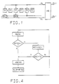
- connections are represented by single wires although they may be constituted by a plurality of such wires.
- the present communication system includes a main station MS connected to a folded unidirectional incoming upstream link UL as well as to a unidirectional outgoing downstream link DL and a plurality of eight or more substations of which only SX, SY and SZ are shown. These substations are coupled in parallel (via gating circuit GC6 for SY and gating circuit GC7 for SX) between the links UL and DL and each of them has an associated data register, such as DX, DY and DZ.
- the main station MS is further for instance coupled to a switching exchange (not shown) via links UL1 and DL1.
- the main station MS and the substations each include a transmitter/receiver and are able to exchange information under the form of information packets of a fixed length, called cells. These on UL are called first cells, and those on DL are called second cells.
- Each of these cells such as the one represented in Fig. 5, comprises a 4-byte header H and a 32-byte information field IF and each header includes a so-called MAC (Media Access Control) field or byte MF and a VCI (Virtual Channel Identifier) constituted by two bytes and identifying the virtual channel on which the cell is transmitted.
- MAC Media Access Control
- VCI Virtual Channel Identifier
- each of the 8 bits of the field MF constitutes a signalling channel between MS and 8 of the substations, whilst the information field IF of the cell is either empty or contains data, signalling channel status information or an address in which case it is a data cell, a check cell or an echo cell respectively.
- the main station MS (Fig. 2) includes a clock recovery circuit CLR1 which is connected to the incoming downstream link DL1 and derives from a cell stream received thereon a cell clock signal CCL1, a word or byte clock signal WCL1 and a bit clock signal BCL1. These clock signals control the various circuits of the main station MS in a way which is not shown but which will become clear from the description of the operation of the station.
- the bit clock signal BCL1 defines a bitframe having a bitrate of 150 Megabit/sec
- the cell clock signal CCL1 defines a cell frame having a cell rate which is 36 x 8 times smaller than the bitrate since each cell comprises 36 x 8 bits.
- the main station MS also includes another clock recovery circuit CLR2 which is connected to the incoming upstream link UL and derives from a cell stream received thereon a cell clock signal CCL2, a word or byte clock signal WCL2 and a bit clock signal BCL2.
- This cell stream is entered into the cell buffer BUF under the control of these clock signals and read therefrom under the control of the clock signals CCL1, WCL1 and BCL1 provided by the clock recovery circuit CLR1. In this way the whole main station operates synchronously under the control of the clock signals provided by CLR1.
- Each of the substations such as SZ (Fig. 3), includes a clock recovery circuit CLR3 which is connected to the incoming down stream link DL and derives from an incoming cell stream on this link a bit clock signal BCL3, a byte or word clock signal WCL3 and a cell clock signal CCL3.
- the clock signals BCL3 and CCL3 define a bitframe and a cell frame respectively and together with the word clock signal WCL3 they control the various circuits of the substation SZ in a way which is not shown but which will become clear from the description of the operation of this station.
- the 8 bit positions of the MAC or signalling field MF of each cell are used as signalling channels and each of them may be allocated to any of the substations so that a maximum of 8 of these substations may simultaneously have signalling channels assigned to them.
- the main station MS stores the general allocation status of all the signalling channels in a register ASR and when it has time to do so it transmits this allocation status to all the substations in the MAC field of a cell.
- This allocation status is stored in a register ALR of each substation.
- each substation having seized a signalling channel, during an allocation procedure, or having a signalling channel allocated to it transmits to the main station a check cell whose information field contains the single or own allocation status stored in a register MBY, i.e. at least one byte of which the bit corresponding to the signalling channel seized or allocated is on 1.
- the main station is informed of the individual allocation states of the various substations and thus can update the general allocation states stored in ASR.
- a substation When a substation is in the active state, i.e. when a signalling channel has been allocated to it during an allocation procedure, and has to transmit a data cell in the direction of the main station, it puts a transmission request bit 1 in the assigned signalling channel of the MAC field of a cell and transmits this cell on the upstream link to the main station. The latter may then allow the requested transmission by putting a grant bit in the assigned signalling channel of a cell which is then transmitted to all the substations. This grant bit will be recognized by the requesting substation which may then transmit the data cell on the upstream link.
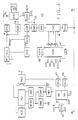
- the main station MS shown in Fig. 2 comprises a transmitter/ receiver including the following circuits which are interconnected as shown:
- the substations all have a similar structure and therefore only one of them, i.e. SZ, is represented in detail in Fig. 3. It includes the following circuits which are interconnected as shown :
- the registers MBY and DIR of the substations SX, SY and SZ are further supposed to be in the following conditions :
- the main station MS is supposed to be in the condition for which :
- the various circuits of the main station MS are controlled by the clock signals provided by the clock recovery circuit CLR1, whilst those of the substations such as SZ are controlled by the clock signals generated by the clock recovery circuit CLR3.
- the clock control of the circuits is not shown in detail but follows from the description of their operation.
- the information is transmitted under the form of cells and in a bit serial way, but in the main station MS as well as in the substations these cells are processed under the form of bytes.
- the required series-to-parallel and parallel-to-series conversions are performed in the above converters SPC1 to SPC3 and PSC1 to PSC3 which will not be considered in detail further.
- the request register REQ is empty its output RE is de-activated (0) so that also the output of gate G1 which constitutes the seletion input SI1 of the multiplexer MUX1 is de-activated (0).
- the output B of the allocation status register ASR is then coupled to the input C of the register REG3.
- Each cell entering the main station MS on the incoming downstream link DL1 is fed via the converter SPC1 to register REG2.
- the detection circuit VD2 checks if this VCI is indicative of an empty cell or of a data cell.
- the output of the gate G2 constituting the selection input SI2 of the multiplexer MUX2 is also de-activated (0).
- the output of register REG2 is connected to the input B of this multiplexer MUX2.
- the cell is then transferred from register REG2 into register REG3 and when the MAC field MF of this cell is present in this register the allocation status 110...0 is copied in it from the general allocation status register ASR
- the cell thus obtained and which is represented in Fig. 5b is then converted in PSC1 and transmitted on the downstream link DL to all the substations and more particularly to SX, SY and SZ to inform them about the general allocation status of the signalling channels.
- this MAC field may also be used to transmit a single grant bit 1 - as will become clear later - so that only when the MAC field contains more than one bit 1 one is sure that an allocation status is concerned. On the contrary, when the MAC field contains a single bit 1 this may either be an allocation bit or a grant bit. To distinguish between these two cases use is made of the counter ASC, as will be explained later.
- the substation SX is in the active state 4 for which the input signals AC and SRO of the finite machine FSM are activated (1) and equal to 4 respectively.
- the request signal R produces the insertion in the MAC field MF of this cell of the own allocation status code 010...0 thus requesting the main station to allow the transmission of a data cell stored in the data cell input register DIR.
- the data cell for which the request is made is then shifted into part WD of the register DIR so that the output WD thereof becomes activated (1).
- the substation SY transmits the check cell (Fig. 7) generated on the folded upstream link UL via the converter PSC3 whose output is connected to UL via gating circuit GC7 (Fig. 1).
- the check VCI of this cell is equal to VC and its MAC field is equal to zero since no transmission request for a data cell is formulated therein.
- the substation SY transmits this check cell (fig. 8) on the folded upstream link UL via the converter PSC3 and the gating circuit GC6 (Fig. 1).
- find-first-zero or find-first-one function is generally known in the art and is for instance mentioned in the Bell System Technical Journal, Volume XLIII, September 1964, Number 5, Part 1, pages 1869-1870.
- the cell assembly circuit CAC creates a cell, shown in Fig. 5e, wherein the MAC field MF is equal to 001...0 indicating that an allocation request for the seized third signalling channel is formulated to the main station MS, and wherein the information field is zero.
- the substation SZ transmits this cell (Fig. 5e) on the folded upstream link UL via the converter SPC4.
- the processing time of each of these substations may be so regulated that the bits of the cell shown in Fig. 5e at the output of SZ may be OR-ed in GC6 with the corresponding bits of the cell represented in Fig. 5d at the output of SY and that the resultant bits may be OR-ed in GC7 with the corresponding bits of the cell shown in Fig. 5c at the output of SX.
- the resultant cell is the check cell shown in Fig. 5f and is transmitted to the main station MS.
- the above MAC field MF detected by MFD is also written in the MAC field register MFR1 and the logic circuit LC2 OR-gates the contents of this register MFR1 with those of the allocation status register ASR and writes the result in the latter register. Because the previous contents of ASR were 110...0 and those of MFR1 are 011...0 the allocation status stored in ASR becomes : 111...0 indicating that channels 1, 2 and 3 have been seized or allocated.
- the above check cell (Fig. 5f) is also supplied to the register REG1 and from there to the link UL1 via the converter PSC2.
- the VCI check circuit VD1 detects the presence of this cell and accordingly activates its output CC.
- the latter enables the gating circuit GC1 so that the information field 110...0, 110...0, etc of the check cell is applied to the filter IFF which selects one of these bytes and applies it to the check byte buffer register CBR.
- the above new contents 111...0 of ASR are then overwritten by the contents 110...0 of CBR so that the contents of ASR again become 110...0 ASR thus stores the present general allocation status. This is correct since the allocation of the third signalling channel to the substation has not yet been granted, i.e. SZ is still not active.
- the output SI1 of the gate G1 is also activated.
- the output A of the request register REQ is connected to the register REG3 via the multiplexer MUX1.
- the substation SX has to request the main station MS to use the allocated (second) signalling channel via a first cells and that it is only able to perform such a transmission after having received a grant signal from MS in this signalling channel of a second cell.
- the main station MS After the main station MS has processed the data cell transmitted to it by the substation SZ it transmits the cell shown in Fig. 5h and containing the above mentioned second code to all the substations such as SX, SY, SZ which are considered hereinafter :
- This station performs no action for the same reasons as described above in relation to the receipt of the cell of Fig. 5g by SY.
- This station performs no action.
- the cell assembly circuit CAC generates an echo cell shown in Fig. 51 and transmits it to the main station MS.
- the information field of this cell is constituted by the own address OA of the substation SZ, this address OA being memorized in the register OAR.
- the MAC field MF is detected by the circuit MFD but because this field is zero nothing is written in the request register REQ and the contents of ASR are not changed.
- the echo cell itself is also applied to the register REG1 where the VCI check circuit VD1 detects the presence of this cell and therefore activates its output EC.
- the latter output signal EC enables the gating circuit GC2 thus allowing the echo cell to be stored in the echo cell register ECR. As a consequence the output EP of ECR is then activated.
- the VCI detection circuit VD2 When the VCI of an empty cell on the incoming link DL1 is entered in the cell register REG2 and is detected by the VCI detection circuit VD2 the latter activates its output signal EMC. Because also the output EP of the register ECR is activated the output SI2 of gate G2 is activated, thus connecting the output A of ECR to the output C of the multiplexer MUX2.
- the echo cell is then transferred to the register REG3 and because the selection input SI1 of the multiplexer MUX1 is de-activated the allocation status ASR 110...0 is stored in the MAC field of the echo cell.
- the thus modified or return echo cell is then transmitted on the downstream link DL to all the substations SX, SY and SZ which are again considered in succession :
- the VCI detection circuit VD3 checks if the VCI, in REG4 is that of an echo cell or not and because the cell is an echo cell it activates its output EO.
- the gating circuit GC5 is enabled and via this circuit the information field IF of the echo cell is transferred into the echo cell register EOR.
- the information field which constitutes the own address of the substation SX is then compared by the comparator COMP2 with the own address OA stored in the register OAR.
- This substation reacts in a similar way as SX to the receipt of the echo return cell and also transmits a check cell to the main station, e.g. the one shown in Fig. 5k.
- the purpose of the programme visualised in Fig. 4 is to store the general allocation status in the register ALR. If the field MF of a cell received in registers REG4 and MF2 contains more than one bit 1 this field certainly is the general allocation status and for this reason the status is then copied from NFR2 into ALR after having reset the counter ASC. On the contrary, if this field MF contains a single bit 1 this bit is either a grant bit or the field MF is a general allocation status with one active station. Only in the latter case the field MF has to be copied in ALR.
- the counter DEC When the part ND of the data input register DIR does not receive new cells so that its output RS remains de-activated the counter DEC is not reset and is stepped under the control of the cell clock CCL3. When the situation lasts for a predetermined time interval the counter DEC will therefore reach a predetermined value for which its output DE becomes de-activated. As a consequence the signalling channel assigned to the substation will then be de-allocated. Indeed, from the above table T2 it then follows that the substation upon receiving the allocation status from the main station will not respond to the main station by means of a check cell and will return to the passive state 1.
- the counter ECC is started upon the transmission of an echo cell by the substation, is stepped under the control of the cell clock signal CCL3 and is reset upon the receipt of a correct return echo cell.
- the counter ECC will reach a predetermined value wherein its ouput ETC is de-activated. From the above table T2 it follows that in this case the state of the substation is changed from state 3 to state 1.
- each substation searches for the first free 0, e.g. the leftmost free 0, in the general allocation status stored in its register ALR.
- the substations thus all have a same priority since any one of them may seize any of the channels. But it is possible to give these substations a predetermined priority e.g. by allowing them to search for a free (leftmost) 0 only in predetermined portions of ALR, the leftmost positions corresponding to the highest priorities.
Landscapes
- Engineering & Computer Science (AREA)
- Computer Networks & Wireless Communication (AREA)
- Signal Processing (AREA)
- Data Exchanges In Wide-Area Networks (AREA)
- Time-Division Multiplex Systems (AREA)
- Mobile Radio Communication Systems (AREA)
- Small-Scale Networks (AREA)
- Radio Relay Systems (AREA)
Claims (23)
- Kommunikationssystem mit einer Anzahl von Unter-Stationen (SX, SZ), die über erste (UL) und zweite (DL) Pfade untereinander verbunden sind, auf denen sich wiederholend erste und zweite Zellen, von denen jede einen Signalisierungskanal und ein Datenfeld enthält, in entgegengesetzten Richtungen transportiert werden, wobei jede Unter-Station einen Sender zum Einschreiben von Informationen in erste Zellen, die eine Anzahl von Signalisierungskanälen enthalten und einen Empfänger zum Auslesen von Informationen aus zweiten Zellen enthält, dadurch gekennzeichnet, daß es eine Haupt-Station (MS) enthält, mit einem weiteren Empfänger zum Auslesen von Informationen aus den genannten ersten Zellen und mit einem weiteren Sender zum Einschreiben von Informationen in die genannten zweiten Zellen, wobei jede der genannten ersten und zweiten Zellen eine Anzahl von Signalisierungskanälen enthält, die kleiner als die Zahl der Unter-Stationen (SX/SZ) ist, daß es Mittel in der genannten Haupt-Station (MS) und den genannten Unter-Stationen (SX/SZ)enthält, um jeder Unterstation, die Daten zu senden hat, irgend einen freien Signalisierungskanal aus der Anzahl der genannten Signalisierungskanäle zuzuteilen, daß es Mittel (FSM, CAC) in jeder Unter-Station (SX), der ein Signalisierungskanal zugeteilt ist, enthält, um in diesem Signalisierungskanal einer ersten Zelle ein Daten-Sende-Anforderungssignal an die genannte Haupt-Station zu senden, und daß es in der genannten Haupt-Station (MS) Mittel (MFD, LC1, REQ) enthält, welche als Antwort auf den Empfang des genannten Sende-Anforderungssignals an die anfordernde Unter-Station (SC) ein Daten-Sende-Bewilligungssignal in einem Signalisierungskanal einer zweiten Zelle sendet.
- Kommunikationssystem nach Anspruch 1, dadurch gekennzeichnet, daß jede der genannten ersten und zweiten Zellen eine gleiche Zahl von Signalisierungskanälen enthält, und daß die genannte Haupt-Station (MS) so ausgestaltet ist, daß sie das genannte Bewilligungssignal in dem Signalisierungskanal der genannten zweiten Zelle sendet, der dem zugeordneten Signalisierungskanal der genannten ersten Zelle entspricht.
- Kommunikationssystem nach Anspruch 1, dadurch gekennzeichnet, daß, um eine Signalisierungskanal-Zuordnungs-Prozedur für eine Unter-Station (SZ) durchzuführen, die neue Daten (ND) an die genannte Haupt-Station (MS) zu senden hat, die Zuteilungs-Mittel enthalten:- in der genannten Unter-Station (SZ) Mittel (PU2), um einen freien Signalisierungskanal aus einem ersten Register (ALR) vorläufig auszuwählen, in dem der allgemeine Zuordnungs-Status von allen Signalisierungskanälen abgespeichert ist, diesen Kanal zu belegen und den so erlangten eigenen Zuordnungs-Status in einem zweiten Register (MBY) abzuspeichern;- in der genannten Unter-Station (SZ) Mittel (FSM, CAC), um ein Anforderungssignal zur Signalisierungskanal-Zuordnung in den ausgewählten Signalisierungskanal einer ersten Zelle (Fig. 5e) zu schreiben, die an die genannte Haupt-Station (MS) gesendet wird;- in der genannten Haupt-Station (MS) Mittel, um ein Zuordnungs-Bewilligungssignal in dem ausgewählten Signalisierungskanal einer zweiten Zelle zu Senden, die an alle genannten Unter-Stationen gesendet wird;- in der genannten Unter-Station (SZ) Mittel (CAC), um eine eigene Adresse (OA) aus einem dritten Register (OAR) dieser Unter-Station in den Daten-Kanal einer ersten Zelle, die als Echo-Zelle dient, zu schreiben, die an die genannte Haupt-Station gesendet wird;- in der genannten Haupt-Station (MS) Mittel (VD1, ELR), um eine empfangene Echo-Zelle zu erkennen und um eine zweite Zelle, die als Echo-Erwiderungs-Zelle dient und ähnlich der empfangenen Echo-Zelle ist, an alle genannten Unter-Stationen zu senden;- in jeder der genannten Unter-Stationen Mittel (COMP2), um die im genannten dritten Register (OAR) gespeicherte Adresse (OA) mit der der genannten Echo-Erwiderungs-Zelle zu vergleichen, wobei der vorläufig ausgewählte Signalisierungskanal entgültig der Unter-Station zugeteilt wird, für die dieser Vergleich erfolgreich verläuft.
- Kommunikationssystem nach Anspruch 3, dadurch gekennzeichnet, daß jede der genannten Unter-Stationen (52) einen endlichen Automaten (FSM) enthält, der so ausgestaltet ist, daß er die Ausführung der genannten Zuordnungs-Prozedur steuert und daß er von einem ersten passiven Normal-Zustand:- in einen zweiten passiven Zustand gebracht wird, wenn die genannte Unter-Station (57) genannte neue Daten (ND) hat, die zu senden sind, und in dem die genannte Unter-Station die genannte Auswahl eines freien Signalisierungskanals durchführt und die genannten Zuordnungs-Anforderungssignale an die genannte Haupt-Station (MS) sendet;- in einen dritten passiven Zustand gebracht wird, wenn die genannte Unter-Station das genannte Zuordnungs-Bewilligungssignal empfängt und in dem die genannte Unter-Station die genannte erste Zelle sendet, die als Echo-Zelle dient;- und in einen vierten, aktiven Zustand gebracht wird, wenn die genannte Unter-Station (SZ) die genannte zweite Zelle, die als Echo-Erwiderungs-Zelle dient, empfängt und der genannte Vergleich erfolgreich verläuft, wobei einer Unter-Station im aktiven Zustand erlaubt wird, die genannten Daten auf einem Datenkanal nach dem Senden eines genannten Sende-Anforderungssignals und dem Empfang eines Sende-Bewillungungssignals zu senden.
- Kommunikationssystem nach Anspruch 3, dadurch gekennzeichnet, daß die genannte Haupt-Station (MS) ein viertes Register (ASR) enthält, in dem der genannte allgemeine Zuordnungs-Status abgespeichert ist und daß die genannte Haupt-Station (MS) Mittel (ASR, MUX1) enthält, um diesen allgemeinen Zuordnungs-Status an alle genannten Unter-Stationen in dem Signalisierungskanal einer zweiten Zelle (Fig. 5b) zu senden, wobei jede Unter-Station (SZ) diesen Status dann in ihrem genannten ersten Register (ALR) abspeichert.
- Kommunikationssystem nach Anspruch 3, dadurch gekennzeichnet, daß die genannte Haupt-Station (MS) eine erste Logik-Schaltung (LC1) enthält, die so ausgestaltet ist, daß sie verschiedene Bewilligungssignale zur Verfügung stellt, wenn die Signalisierungskanäle einer empfangenen ersten Zelle mehr als ein Zuordnungs- oder Sende-Anforderungssignal enthalten und daß sie die genannten verschiedenen Bewilligungssignale nacheinander in ein fünftes Register (REQ) speichert, das als Anforderungs-Register dient, um nacheinander jedes Bewilligungssignal in dem zugeordneten Signalisierungskanal einer zweiten Zelle an die genannte Unter-Station zu senden.
- Kommunikationssystem nach Anspruch 5 und 6, dadurch gekennzeichnet, daß die genannte Haupt-Station (MS) so ausgestaltet ist, daß sie allgemeine Status-Informationen, die im genannten vierten Register (ASR) abgespeichert sind, an die genannten Unter-Stationen (SX/SZ) sendet, falls das genannte fünfte Register (REQ) leer ist.
- Kommunikationssystem nach Anspruch 6, dadurch gekennzeichnet, daß die genannte Haupt-Station (MS) so ausgestaltet ist, daß sie die genannte allgemeine Status-Information, die im genannten vierten Register (ASR) gespeichert ist, sendet, wenn ein erstes vorbestimmtes Zeitintervall, das von einem ersten Zähler (TC) abgezählt wird, seit dem vorhergehenden Senden der genannten allgemeinen Status-Information verstrichen ist.
- Kommunikationssystem nach Anspruch 5, dadurch gekennzeichnet, daß jede der genannten Unter-Stationen (SC/SY) so ausgestaltet ist, daß sie ihren genannten eigenen Zuordnungs-Status an die genannte Haupt-Station (MS) in dem Datenkanal einer ersten Zelle, die als Kontroll-Zelle dient, sendet, daß die genannte Haupt-Station (MS) so ausgestaltet ist, daß sie das Ergebnis einer Oder-Verknüpfung dieser Kontroll-Zellen empfängt und daß sie die so erhaltene sich ergebende Kontroll-Zelle dazu verwendet, den in ihrem genannten vierten Register (ASR) abgespeicherten allgemeinen Zuordnungs-Status auf den neuesten Stand zu bringen.
- Kommunikationssystem nach Anspruch 9, dadurch gekennzeichnet, daß die genannte erste Zelle, die als Kontroll-Zelle dient, eine Anzahl von Sets enthält, von denen jedes von einem genannten eigenen Zuordnungs-Status gebildet wird.
- Kommunikationssystem nach Anspruch 1, dadurch gekennzeichnet, daß jeder Signalisierungskanal von einer einzelnen Bit-Position in einem Signalisierungs-Feld (M) gebildet wird.
- Kommunikationssystem nach Anspruch 1, dadurch gekennzeichnet, daß jede der genannten Unter-Stationen (SZ) Freigabe-Mittel (DEC) enthält, die einen vorher belegten Signalisierungskanal freigeben, wenn ein zweites vorbestimmtes Zeitintervall seit dem letzten Empfang von neuen Daten (ND), die zu senden sind, verstrichen ist.
- Kommunikationssystem nach Anspruch 9 und 12, dadurch gekennzeichnet, daß es einen zweiten Zähler (DEC) zum Abzählen des genannten zweiten vorbestimmten Zeitintervalls enthält, wobei das aktivierte Ausgangs-Signal (DE) des genannten zweiten Zählers (DEC) die Unter-Station davon abhält, an die genannte Haupt-Station (MS) eine erste Zelle zu senden, die als Kontroll-Zelle dient und ihren eigenen Zuordnungs-Zustand enthält.
- Kommunikationssystem nach Anspruch 1, dadurch gekennzeichnet, daß jede (SZ) der genannten Unter-Stationen Mittel enthält, um zu kontrollieren, ob einer oder mehrere der Signalisierungskanäle einer empfangenen zweiten Zelle belegt sind und um einen dritten Zähler (ASC) zu erhöhen, wenn ein einzelner belegter Signalisierungskanal erkannt worden ist, und daß jede der genannten Unter-Stationen so ausgestaltet ist, daß der genannte dritte Zähler (ASC) zurückgesetzt und der Status der Signalisierungskanäle der genannten empfangenen Zelle in das erste Register (ALR) kopiert wird, nachdem er einen vorbestimmten Wert (TC1) abgezählt hat oder wenn mehr als ein belegter Signalisierungskanal erkannt wird.
- Kommunikationssystem nach Anspruch 13, dadurch gekennzeichnet, daß jede der genannten Unter-Stationen (SZ) ein sechstes Register (DIR) mit einem ersten Teil (ND) zum Speichern von neuen Daten, die zu senden sind und für die kein Daten-Sende-Anforderungssignal zur genannten Haupt-Station (MS) gesendet worden ist und mit einem zweiten Teil (WD) zum Speichern von Daten enthält, für die solch ein Anforderungssignal gesendet worden ist, wobei der genannte zweite Zähler (DC) dem ersten Teil (ND) zugeordnet ist.
- Kommunikationssystem nach Anspruch 3, dadurch gekennzeichnet, daß die genannte Haupt-Station (MS) so ausgestaltet ist, daß sie die genannte zweite Zelle, die als Echo-Erwiderungs-Zelle dient, in eine leere zweite Zelle schreibt.
- Kommunikationssystem nach Anspruch 1, dadurch gekennzeichnet, daß der genannte erste Pfad (UL) gefaltet ist und einen ersten Teil, der mit den genannten Unter-Stationen (SX/SZ) verbunden ist, und einen zweiten Teil enthält, der mit der genannten Haupt-Station (MS) derart verbunden ist, daß die Länge der Verbindung von der Haupt-Station (MS) über irgend eine Unter-Station (SX/SZ) und zurück zu der Haupt-Station im Wesentlichen konstant ist.
- Kommunikationssystem nach Anspruch 7 und 8, dadurch gekennzeichnet, daß die genannte Haupt-Station (MS) einen ersten Multiplexer (MUX1) enthält, mit einem ersten Daten-Eingang (A), der mit einem Ausgang des genannten fünften Registers (REQ) verbunden ist, mit einem zweiten Daten-Eingang (B), der mit einem Ausgang des genannten vierten Registers (ASR) verbunden ist, mit einem Auswahl-Eingang (SI1), der mit dem Ausgang von ersten Verknüpfungs-Mitteln (G1) verbunden ist, die von dem Ausgang (RE), der den leer/nicht-leer-Zustand des genannten fünften Registers (REQ) anzeigt und von einem Ausgang des genannten ersten Zählers (TC) gesteuert werden und mit einem Ausgang (C), der über ein sechstes Register (M) mit dem genannten zweiten Pfad (DL) verbunden ist.
- Kommunikationssystem nach Anspruch 5 und 6, dadurch gekennzeichnet, daß die genannte Haupt-Station (MS) weiter eine Schaltung zur Signalisierungskanal-Ermittlung enthält (MFD), um den genannten ersten Pfad (UL) mit dem Daten-Eingang des genannten fünften Registers (REQ) über die genannte erste Logik-Schaltung (LC1) sowie mit dem genannten vierten Register (ASR) über eine zweite Logik-Schaltung (LC2) zu verbinden, die so ausgestaltet ist, daß sie den Inhalt des genannten vierten Registers (ASR) mit dem der genannten Signalisierungskanäle oder - verknüpft und daß sie das Ergebnis in das genannte vierte Register (ASR) abspeichert.
- Kommunikationssystem nach Anspruch 9, dadurch gekennzeichnet, daß die genannte Haupt-Station (MS) weiter eine erste Erkennungsschaltung (VD1) für Echo-Zellen und Kontroll-Zellen enthält, um eine zweite Verknüpfungs-Schaltung (GC1) und eine dritte Verknüpfungs-Schaltung (GC2) freizugeben, falls die genannte sich ergebende Kontroll-Zelle bzw. eine Echo-Zelle von der genannten ersten Erkennungs-Schaltung (VD1) erkannt wurde, und daß der erste Pfad (UL) mit der genannten ersten Erkennungs-Schaltung (VD1) verbunden ist.
- Kommunikationssystem nach Anspruch 20, dadurch gekennzeichnet, daß die frei gegebene zweite Verknüpfungs-Schaltung (GC1) so ausgestaltet ist, daß sie es einer zugeordneten Schaltung (LFF, CBC) gestattet, den Status des Signalisierungs-Kanals zu überschreiben, der im genannten vierten Register (ASR) abgespeichert ist.
- Kommunikationssystem nach Anspruch 16 und 20, dadurch gekennzeichnet, daß die freigegebene dritte Verknüpfungs-Schaltung (GC2) so ausgestaltet ist, daß sie es gestattet, daß die genannte Echo-Zelle an einen ersten Daten-Eingang eines zweiten Multiplexers (MUX2) über ein siebtes Register (ECR) angelegt wird, wobei der zweite Multiplexer (MUX2) einen zweiten Daten-Eingang (B), der mit dem genannten zweiten Pfad verbunden ist und einen Auswahl-Eingang (SI2) hat, der von dem Ausgang einer vierten Verknüpfungs-Schaltung (G2) gesteuert wird, die ein aktiviertes Ausgangs-Signal zur Verfügung stellt, wenn gleichzeitig eine leere Zelle von einer zweiten Erkennungs-Schaltung (VD) auf dem genannten zweiten Pfad erkannt wird und sich eine Echo-Zelle in dem genannten siebten Register (ECR) befindet, wobei der Ausgang des genannten zweiten Multiplexers (MUX2) mit dem genannten zweiten Pfad verbunden wird.
- Kommunikationssystem nach Anspruch 3, dadurch gekennzeichnet, daß die genannte Unter-Station einen vierten Zähler (ECC) enthält, um die Zeit abzuzählen, die seit dem Aussenden einer Echo-Zelle verstrichen ist, und um ein aktiviertes Ausgangs-Signal (ETC) zur Verfügung zu stellen, wenn keine Echo-Zelle empfangen wird, wodurch die Signalisierungskanal-Zuordnung dann von den genannten Zuordnungs-Mittel (FSM) verhindert wird.
Applications Claiming Priority (1)
| Application Number | Priority Date | Filing Date | Title |
|---|---|---|---|
| PCT/EP1989/000728 WO1991000662A1 (en) | 1989-06-23 | 1989-06-23 | Communication system |
Publications (2)
| Publication Number | Publication Date |
|---|---|
| EP0430955A1 EP0430955A1 (de) | 1991-06-12 |
| EP0430955B1 true EP0430955B1 (de) | 1994-06-01 |
Family
ID=8165405
Family Applications (1)
| Application Number | Title | Priority Date | Filing Date |
|---|---|---|---|
| EP89907717A Expired - Lifetime EP0430955B1 (de) | 1989-06-23 | 1989-06-23 | Kommunikationssystem |
Country Status (8)
| Country | Link |
|---|---|
| US (1) | US5331316A (de) |
| EP (1) | EP0430955B1 (de) |
| JP (1) | JPH0767111B2 (de) |
| AU (1) | AU630876B2 (de) |
| CA (1) | CA2019594C (de) |
| DE (1) | DE68915768T2 (de) |
| ES (1) | ES2024293A6 (de) |
| WO (1) | WO1991000662A1 (de) |
Families Citing this family (18)
| Publication number | Priority date | Publication date | Assignee | Title |
|---|---|---|---|---|
| DE69116676D1 (de) * | 1991-03-27 | 1996-03-07 | Ibm | Einfüge- und Entfernungssignalisierung in LAN Systemen |
| JPH05260045A (ja) * | 1992-01-14 | 1993-10-08 | Ricoh Co Ltd | デ−タ端末装置の通信方法 |
| EP0582754A1 (de) * | 1992-08-11 | 1994-02-16 | Alcatel Bell-Sdt S.A. | Bewegliche Übertragungsanordnung mit linearer digitaler Modulationsvorrichtung |
| EP0616444A3 (de) * | 1993-03-15 | 1994-10-19 | Koninkl Philips Electronics Nv | Telekommunikationssystem mit Abstandsmessung. |
| GB2281470B (en) * | 1993-04-02 | 1998-07-15 | Motorola Ltd | Multichannel random access communications system |
| DE69531012T2 (de) * | 1994-03-09 | 2004-05-19 | Matsushita Electric Industrial Co., Ltd., Kadoma | Datenübertragungssystem und Verfahren |
| US5799018A (en) * | 1994-05-19 | 1998-08-25 | Nippon Telegraph And Telephone Corp. | Method and system for private communication with efficient use of bus type transmission path |
| US5563883A (en) * | 1994-07-18 | 1996-10-08 | Cheng; Alexander L. | Dynamic channel management and signalling method and apparatus |
| US5553071A (en) * | 1994-10-14 | 1996-09-03 | Lucent Technologies Inc. | Communication system topology providing dynamic allocation of B-channels |
| US5648958A (en) * | 1995-04-05 | 1997-07-15 | Gte Laboratories Incorporated | System and method for controlling access to a shared channel for cell transmission in shared media networks |
| US5615338A (en) * | 1995-05-24 | 1997-03-25 | Titan Information Systems Corporation | System for simultaneously displaying video signal from second video channel and video signal generated at that site or video signal received from first channel |
| US5702433A (en) * | 1995-06-27 | 1997-12-30 | Arrow International Investment Corp. | Kink-resistant steerable catheter assembly for microwave ablation |
| GB9602027D0 (en) * | 1996-02-01 | 1996-04-03 | Madge Networks Ltd | Flow control in a cell switched communication system |
| EP0841776A1 (de) * | 1996-11-12 | 1998-05-13 | Sony Corporation | Kommunikationsverfahren und elektronisches Gerät |
| KR100446515B1 (ko) | 1997-09-13 | 2004-11-12 | 삼성전자주식회사 | 무선 통신시스템의 접속 방법 |
| US6195565B1 (en) * | 1998-03-03 | 2001-02-27 | Lucent Technologies Inc. | Bandwidth control in a packet-based data system |
| JP2002204245A (ja) * | 2000-12-28 | 2002-07-19 | Mitsubishi Electric Corp | 信号出力装置、信号出力方法及び信号出力方法をコンピュータに実行させるためのプログラムを記録したコンピュータ読み取り可能な記録媒体 |
| FR2838005B1 (fr) * | 2002-03-28 | 2004-12-24 | Cit Alcatel | Methode dynamique d'insertion de donnees aux noeuds d'un reseau de transmission optique |
Family Cites Families (5)
| Publication number | Priority date | Publication date | Assignee | Title |
|---|---|---|---|---|
| CA893337A (en) * | 1969-11-10 | 1972-02-15 | Ibm Canada Limited - Ibm Canada Limitee | Data communication system |
| US4554656A (en) * | 1982-08-11 | 1985-11-19 | At&T Bell Laboratories | Method and system for controlling the interconnecting of a plurality of local data networks |
| AU591645B2 (en) * | 1984-12-03 | 1989-12-14 | John Leslie Hullett | Queueing protocol |
| GB8518133D0 (en) * | 1985-07-18 | 1985-08-21 | British Telecomm | Communications network |
| GB2197563A (en) * | 1986-11-13 | 1988-05-18 | Plessey Co Plc | Data switching arrangement |
-
1989
- 1989-06-23 DE DE68915768T patent/DE68915768T2/de not_active Expired - Fee Related
- 1989-06-23 US US07/613,512 patent/US5331316A/en not_active Expired - Fee Related
- 1989-06-23 EP EP89907717A patent/EP0430955B1/de not_active Expired - Lifetime
- 1989-06-23 WO PCT/EP1989/000728 patent/WO1991000662A1/en not_active Ceased
- 1989-06-23 AU AU38557/89A patent/AU630876B2/en not_active Ceased
- 1989-06-23 JP JP1507210A patent/JPH0767111B2/ja not_active Expired - Fee Related
-
1990
- 1990-06-22 ES ES9001749A patent/ES2024293A6/es not_active Expired - Lifetime
- 1990-06-22 CA CA002019594A patent/CA2019594C/en not_active Expired - Fee Related
Also Published As
| Publication number | Publication date |
|---|---|
| ES2024293A6 (es) | 1992-02-16 |
| JPH0767111B2 (ja) | 1995-07-19 |
| CA2019594C (en) | 1998-08-18 |
| US5331316A (en) | 1994-07-19 |
| CA2019594A1 (en) | 1990-12-23 |
| EP0430955A1 (de) | 1991-06-12 |
| WO1991000662A1 (en) | 1991-01-10 |
| AU630876B2 (en) | 1992-11-12 |
| JPH04500441A (ja) | 1992-01-23 |
| DE68915768D1 (de) | 1994-07-07 |
| AU3855789A (en) | 1991-01-17 |
| DE68915768T2 (de) | 1994-09-15 |
Similar Documents
| Publication | Publication Date | Title |
|---|---|---|
| US5331316A (en) | Communication system including allocating free signalling channels to individual substations having data to transmit | |
| AU713048B2 (en) | Media access control for digital data | |
| US4383315A (en) | Idle time slot seizure and transmission facilities for loop communication system | |
| EP0462349B1 (de) | Breitbandringkommunikationssystem und Zugriffssteuerungsverfahren | |
| US4763319A (en) | Multi-rate synchronous virtual circuit network for voice and data communications | |
| US3985962A (en) | Method of information transmission with priority scheme in a time-division multiplex communication system comprising a loop line | |
| US4413337A (en) | Time division switching system for circuit mode and packet mode lines | |
| AU591645B2 (en) | Queueing protocol | |
| US4413338A (en) | Communication system for interconnecting a plurality of asynchronous data processing terminals | |
| EP0130206B1 (de) | Verfahren und gerät für bus-konkurrenzbetriebsentscheidung | |
| US4586175A (en) | Method for operating a packet bus for transmission of asynchronous and pseudo-synchronous signals | |
| US4463351A (en) | System for providing several data terminals with access to a digital telephone line | |
| US6212196B1 (en) | Multiple access communication system and method for multiple access communication | |
| EP0427871B1 (de) | Verbindungssystem zwischen netzwerken | |
| JPS6338130B2 (de) | ||
| CA1264844A (en) | Time division switching system having a priority selector responsive to proceed-to-send requests | |
| US6490264B1 (en) | Data transmission method and system | |
| JPH0626341B2 (ja) | 通信装置 | |
| CA2120542C (en) | Cell relay transport mechanism | |
| US4841523A (en) | Method of accessing local area networks with a unidirectional ring-transmission line, and local area network using this method | |
| US5339314A (en) | Packet data transmission unit having occupied, idle, and released states therefor | |
| US5912890A (en) | Statistical multiplexing apparatus in a time division multiplexing bus | |
| US5257258A (en) | "Least time to reach bound" service policy for buffer systems | |
| EP0952693A2 (de) | Vorrichtung zum Packetmultiplexen | |
| AU645098B2 (en) | Bus transmission |
Legal Events
| Date | Code | Title | Description |
|---|---|---|---|
| PUAI | Public reference made under article 153(3) epc to a published international application that has entered the european phase |
Free format text: ORIGINAL CODE: 0009012 |
|
| AK | Designated contracting states |
Kind code of ref document: A1 Designated state(s): BE CH DE FR GB LI SE |
|
| 17P | Request for examination filed |
Effective date: 19910613 |
|
| 17Q | First examination report despatched |
Effective date: 19930428 |
|
| GRAA | (expected) grant |
Free format text: ORIGINAL CODE: 0009210 |
|
| AK | Designated contracting states |
Kind code of ref document: B1 Designated state(s): BE CH DE FR GB LI SE |
|
| REF | Corresponds to: |
Ref document number: 68915768 Country of ref document: DE Date of ref document: 19940707 |
|
| ET | Fr: translation filed | ||
| EAL | Se: european patent in force in sweden |
Ref document number: 89907717.6 |
|
| PLBE | No opposition filed within time limit |
Free format text: ORIGINAL CODE: 0009261 |
|
| STAA | Information on the status of an ep patent application or granted ep patent |
Free format text: STATUS: NO OPPOSITION FILED WITHIN TIME LIMIT |
|
| 26N | No opposition filed | ||
| PGFP | Annual fee paid to national office [announced via postgrant information from national office to epo] |
Ref country code: CH Payment date: 20010517 Year of fee payment: 13 |
|
| PGFP | Annual fee paid to national office [announced via postgrant information from national office to epo] |
Ref country code: SE Payment date: 20010531 Year of fee payment: 13 |
|
| PGFP | Annual fee paid to national office [announced via postgrant information from national office to epo] |
Ref country code: BE Payment date: 20010621 Year of fee payment: 13 |
|
| REG | Reference to a national code |
Ref country code: GB Ref legal event code: IF02 |
|
| PG25 | Lapsed in a contracting state [announced via postgrant information from national office to epo] |
Ref country code: SE Free format text: LAPSE BECAUSE OF NON-PAYMENT OF DUE FEES Effective date: 20020624 |
|
| PG25 | Lapsed in a contracting state [announced via postgrant information from national office to epo] |
Ref country code: LI Free format text: LAPSE BECAUSE OF NON-PAYMENT OF DUE FEES Effective date: 20020630 Ref country code: CH Free format text: LAPSE BECAUSE OF NON-PAYMENT OF DUE FEES Effective date: 20020630 Ref country code: BE Free format text: LAPSE BECAUSE OF NON-PAYMENT OF DUE FEES Effective date: 20020630 |
|
| BERE | Be: lapsed |
Owner name: *ALCATEL BELL Effective date: 20020630 |
|
| EUG | Se: european patent has lapsed | ||
| REG | Reference to a national code |
Ref country code: CH Ref legal event code: PL |
|
| PGFP | Annual fee paid to national office [announced via postgrant information from national office to epo] |
Ref country code: GB Payment date: 20030530 Year of fee payment: 15 |
|
| PGFP | Annual fee paid to national office [announced via postgrant information from national office to epo] |
Ref country code: DE Payment date: 20030603 Year of fee payment: 15 |
|
| PGFP | Annual fee paid to national office [announced via postgrant information from national office to epo] |
Ref country code: FR Payment date: 20030611 Year of fee payment: 15 |
|
| PG25 | Lapsed in a contracting state [announced via postgrant information from national office to epo] |
Ref country code: GB Free format text: LAPSE BECAUSE OF NON-PAYMENT OF DUE FEES Effective date: 20040623 |
|
| PG25 | Lapsed in a contracting state [announced via postgrant information from national office to epo] |
Ref country code: DE Free format text: LAPSE BECAUSE OF NON-PAYMENT OF DUE FEES Effective date: 20050101 |
|
| GBPC | Gb: european patent ceased through non-payment of renewal fee |
Effective date: 20040623 |
|
| PG25 | Lapsed in a contracting state [announced via postgrant information from national office to epo] |
Ref country code: FR Free format text: LAPSE BECAUSE OF NON-PAYMENT OF DUE FEES Effective date: 20050228 |
|
| REG | Reference to a national code |
Ref country code: FR Ref legal event code: ST |