EP0431070B1 - Cassette de film en feuille - Google Patents
Cassette de film en feuille Download PDFInfo
- Publication number
- EP0431070B1 EP0431070B1 EP89910445A EP89910445A EP0431070B1 EP 0431070 B1 EP0431070 B1 EP 0431070B1 EP 89910445 A EP89910445 A EP 89910445A EP 89910445 A EP89910445 A EP 89910445A EP 0431070 B1 EP0431070 B1 EP 0431070B1
- Authority
- EP
- European Patent Office
- Prior art keywords
- cassette
- hinge
- projection
- sheet
- film
- Prior art date
- Legal status (The legal status is an assumption and is not a legal conclusion. Google has not performed a legal analysis and makes no representation as to the accuracy of the status listed.)
- Expired - Lifetime
Links
Images

Classifications
-
- G—PHYSICS
- G03—PHOTOGRAPHY; CINEMATOGRAPHY; ANALOGOUS TECHNIQUES USING WAVES OTHER THAN OPTICAL WAVES; ELECTROGRAPHY; HOLOGRAPHY
- G03B—APPARATUS OR ARRANGEMENTS FOR TAKING PHOTOGRAPHS OR FOR PROJECTING OR VIEWING THEM; APPARATUS OR ARRANGEMENTS EMPLOYING ANALOGOUS TECHNIQUES USING WAVES OTHER THAN OPTICAL WAVES; ACCESSORIES THEREFOR
- G03B42/00—Obtaining records using waves other than optical waves; Visualisation of such records by using optical means
- G03B42/02—Obtaining records using waves other than optical waves; Visualisation of such records by using optical means using X-rays
- G03B42/04—Holders for X-ray films
Definitions
- the invention relates to a sheet-film cassette
- a sheet-film cassette comprising a lower cassette portion serving to position the sheet film, an upper cassette portion forming the cassette lid and including sheet-film pressure means, a narrow side wall connected to said lower portion, said upper cassette portion being held to said side wall, and thereby to said lower cassette portion, by a hinge, said hinge extending in a direction parallel to said side wall and having a surface aligned with the outer surface of said side wall, one part of the hinge being connected to the side wall, a second part of the hinge being connected to the upper cassette portion, the cassette also having a closing device which is arranged on the side of the cassette opposite to said hinge, the hinge further comprising a first projection, which extends from the part of the hinge connected to the side wall in a direction parallel with the hinge and projects into the interior of the cassette, a second projection which extends from the part of the hinge connected to the upper cassette portion in a direction parallel with the first projection and projects into the interior of the cassette.
- the cassette lid is hinged to the lower cassette portion by a hinge made of flexible material and comprising a pivot zone formed by a thinned section and having two claw-like holding elements to connect the cassette portions.
- the cassette lid is hinged to the lower cassette portion by a plastic hinge, a flexible pivot zone being formed by a thinned section of the material at the hinge.
- the hinge is fastened to a thin wall of the lower cassette portion which in a manner known per se serves for positioning the cassette and for moving an X-ray film into close contact with a portion adapted to receive said film.
- this object is attained in that when the cassette is closed the second projection engages the first projection from below, whereby the projections support each other.
- the hinge consists of a flexible material and has a ledge-shaped profile with a pivot zone formed by a thinned section of the material. Holding elements extending in the longitudinal direction on either side of said pivot zone are provided for the cassette portions as well as for the projections required for the support according to the invention and for further elements provided for light-sealing purposes.
- the cassette which is unstable in the area of the thin wall and the pivot zone of the hinge when in its open position, is stabilized when the cassette is closed.
- the cassette lid and its pressure means respectively can exert uniform pressure on the film across the whole length of the hinge.
- the invention will be described with reference to an X-ray sheet-film cassette which is preferably used for mamographic purposes and to this end is designed with a relatively thin end wall so that the Xray film can be moved as closely as possible to the body.
- the cassette 1 comprises a lower portion 2 to which a lid 3 is hinged by means of a hinge 4.
- Lid 3 can be locked with a lower portion 2 of cassette 1 by means of a closing device 7 of a type known per se and not illustrated in detail, which can be actuated either automatically or manually.
- the lower portion 2 of cassette 1 has a support surface 2d for a sheet film 10, said support surface being surrounded by a circumferential wall 2a, 2b of which wall portion 2b is thin and directly forms the outer wall of a narrow side of cassette 1.
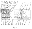
- Two spring elements 5, 6 are mounted to the lower portion 2 in a position opposite to the thin wall 2b (Fig. 2) by hot rivets 11 with a slight pretention. As illustrated in Fig. 3, the free ends of the spring elements 5, 6 extend into the closed receiving space for the sheet film 10 and into recesses 2e of the support surface 2d.
- Hinge 4 by which the lower portion 2 and the lid 3 are pivotably connected consists of a flexible material and, as shown in Fig. 3, has a ledge-shaped profile with a thinned section which forms a pivot zone 4i. Holding elements extending over the whole length of the hinge are molded on either side of said pivot zone 4i for mounting the lower portion 2 and the lid 3 respectively. On the side of the lid, these holding elements are formed by ledges 4a, 4b which enclose in a clawlike manner a T-shaped end section 3c of lid 3.
- Ledges 4f and 4h molded to hinge 4 also enclose also in a clawlike manner a beadlike portion 2f of thin wall 2b of lower portion 2.
- hinge 4 extends over the total length of hinge 4 so that the hinge is protected against the entrance of light when cassette 1 is closed.
- the end sides of hinge 4 are, moreover, covered by lateral projections 3a and 3b of lid 3 (see Fig. 2) as well as by intermediate labyrinth-type webs (not illustrated) on the lower portion 2 and are thus sealed against the entrance of light.
- Hinge 4 does not project beyond the plane of the outer surface 2c of the lower portion 2. Hinge 4 is fastened on the lower portion 2 and on lid 3 by plugging and/or snapping.
- film pressure means of a type known per se are provided, said means comprising a foamed-plastic plate 8 and an intensifying screen 9 arranged thereon and extending directly up to the inner surface 2g of the thin wall 2b.
- the foamed-plastic plate 8 is mounted on the inner side of lid 3, which is not shown in detail, and is reinforced by ribs 3d arranged in a grid pattern.
- the lower portion 2 and the lid 3 of cassette 1 are provided with walls interlocking in a known labyrinth-type configuration not illustrated to prevent light from entering the cassette.
- lid 3 When lid 3 is closed, one of those walls 3e arranged on lid 3 (see Fig. 3) extends into the range of pivotal movement of the spring elements 5 and 6 and displaces said elements laterally.
- the obliquely positioned spring elements 5, 6 (shown in dash-dotted lines) direct the sheet film 10 into the receiving chamber of the cassette 1 such that its front edge is moved into direct contact with the inner surface 2g of thin wall 2b.
- lid 3 is closed. During such operation ledge 4d associated with lid 3 moves below ledge 4f associated with the thin wail 2b of lower portion 2 so that the inclined surfaces 4e and 4g of said ledges are brought into positive engagement.
- lid 3 is reliably supported and the whole area of the hinge is stabilized so that lid 3 exerts uniform pressure over the total width of the cassette.
- the inclined surface 4g of ledge 4f acts on the inclined surface 4e of ledge 4d to press lid 3 together with foamed-plastic plate 8 and intensifying screen 9 onto sheet film 10 placed in lower portion 2, 2d.
- the relatively high initial pressure results in the intimate contact required between intensifying screen 9 and sheet film 10.
- the rolling effect between sheet film 10 and pressure means 8 and 9 initiated during closing of the lid 3 - and subjecting the surface to low pressure - is continued due to a slightly curved design of the inner side of lid 3 (not illustrated) and a slightly drum-shaped design of the support surface 2d in the lower portion 2 (not illustrated either) until cassette 1 is closed. Thanks to the rolling effect during closing of cassette 1, air cannot be entrapped between sheet film 10 and its contact surfaces 2d and 9.
- one of the longer sides of the hinge can also be molded directly to the lid or to the lower portion.
- the lower portion, the hinge and the lid can form an integral unit (not illustrated).
- FIG. 1 Another modification of the illustrated embodiment may consist in that (not illustrated) one or both support ledges 4d, 4f form part of lower portion 2 and cassette lid 3 respectively, with the hinge 4 otherwise designed in the described manner or in another manner known per se.
- the design of the hinge area according to the invention is advantageous not only for a cassette as shown in the embodiment but also for a cassette in which the hinge area must be stabilized in order to attain smaller cassette dimensions.
Landscapes
- Physics & Mathematics (AREA)
- General Physics & Mathematics (AREA)
- Packaging Of Annular Or Rod-Shaped Articles, Wearing Apparel, Cassettes, Or The Like (AREA)
- Radiography Using Non-Light Waves (AREA)
Abstract
Claims (8)
- Cassette (1) pour feuille de film comprenant une partie inférieure (2) servant à positionner la feuille de film (10) et une partie supérieure (3) formant le couvercle et comprenant un organe de pression (8) de la feuille de film, une paroi latérale (2b) de petite dimension reliée à la partie inférieure (2), ladite partie supérieure (3) étant rattachée à ladite paroi latérale (2b), et de ce fait à la partie inférieure (2), grâce à une articulation (4) qui s'étend parallèlement à ladite paroi latérale (2b) et dont l'une des surfaces est alignée avec la surface externe (2c) de ladite paroi latérale (2b), une première partie de l'articulation (4) étant reliée à la paroi latérale et une seconde partie de l'articulation étant reliée à la partie supérieure (3), la cassette (1) étant aussi munie d'un dispositif de verrouillage (7) disposé sur la cassette à l'opposé de ladite articulation (4), l'articulation comprenant une première excroissance (4f) qui fait saillie de la partie de ladite articulation reliée à la paroi latérale (2b) parallèlement à ladite articulation (4) et qui déborde vers l'intérieur de la cassette, une deuxième excroissance (4d) fait saillie de la partie de l'articulation (4) reliée à la partie supérieure (3) de la cassette parallèlement à ladite première excroissance (4f) vers l'intérieur de ladite cassette, caractérisée en ce que lorsque la cassette est fermée la deuxième excroissance vient au contact du dessous de la première excroissance (4f) et de ce fait les excroissances (4d, 4f) se supportent mutuellement.
- Cassette selon la revendication 1, caractérisée en ce que les zones de contact entre la première et la seconde excroissance (4d, 4f) présentent des surfaces inclinées (4e, 4g) qui permettent à la partie supérieure (3) de la cassette de basculer librement.
- Cassette selon l'une des revendications 1 ou 2, caractérisée en ce que les zones de contact (4e, 4g) de la première et de la seconde excroissance (4d, 4f) fournissent, lorsqu'elles coopèrent, une étanchéité à la lumière.
- Cassette selon l'une quelconque des revendications 1 à 3, caractérisée en ce que l'articulation (4) est réalisée en un matériau flexible et comprend une zone de basculement (4i) formée d'une partie amincie dudit matériau flexible et des éléments de fixation (4a, 4b, 4f, 4h), en forme de crochets, agencés de part et d'autre de ladite zone amincie et coopérant avec lesdites parties inférieure et supérieure (2,3) de la cassette.
- Cassette selon la revendication 4, caractérisé en ce que l'articulation (4) présente dans le sens longitudinal un profil à saillies ayant les éléments de fixation (4a, 4b, 4f, 4h), les excroissances (4d, 4f, 4j), les surfaces inclinées (4e, 4g) et une découpe (4k).
- Cassette selon les revendications 4 ou 5, caractérisé en ce que les éléments de fixation (4a, 4b ; 4f, 4h) en forme de crochets coopèrent avec des structures correspondantes (2f ; 3c) respectivement de la partie inférieure (2) et de la partie supérieure (3) de la cassette.
- Cassette selon l'une ou plusieurs des revendications 1 à 6, caractérisée en ce que la première excroissance (4f) est agencée sur celui des éléments de fixation (4f, 4h) de l'articulation (4) associé à la partie inférieure (2) de la cassette et en ce que la deuxième excroissance (4d) est agencé sur celui des éléments de fixation (4a, 4b) associé à la partie supérieure (3) de la cassette.
- Cassette selon l'une ou plusieurs des revendications 1 à 7, caractérisée en ce qu'une troisième excroissance (4j) est disposée sur l'élément de fixation (4f, 4h) associé à la partie inférieure (2) de la cassette, ladite troisième excroissance recouvrant ladite première excroissance et étant agencé de manière à être pratiquement parallèle à cette première excroissance en faisant saillie vers l'intérieur de la cassette et en ce que lorsque la cassette (1) est fermée, ladite troisième excroissance (4j) pénètre dans une découpe (4k) de l'élément de fixation (4a, 4b) associé à la partie supérieure (3) de la cassette de manière à réaliser une forme de labyrinthe.
Priority Applications (1)
| Application Number | Priority Date | Filing Date | Title |
|---|---|---|---|
| AT89910445T ATE96551T1 (de) | 1988-08-30 | 1989-08-28 | Blattfilmkassette. |
Applications Claiming Priority (2)
| Application Number | Priority Date | Filing Date | Title |
|---|---|---|---|
| DE3829313A DE3829313C2 (de) | 1988-08-30 | 1988-08-30 | Planfilmkassette |
| DE3829313 | 1988-08-30 |
Publications (2)
| Publication Number | Publication Date |
|---|---|
| EP0431070A1 EP0431070A1 (fr) | 1991-06-12 |
| EP0431070B1 true EP0431070B1 (fr) | 1993-10-27 |
Family
ID=6361836
Family Applications (1)
| Application Number | Title | Priority Date | Filing Date |
|---|---|---|---|
| EP89910445A Expired - Lifetime EP0431070B1 (fr) | 1988-08-30 | 1989-08-28 | Cassette de film en feuille |
Country Status (4)
| Country | Link |
|---|---|
| US (1) | US5146484A (fr) |
| EP (1) | EP0431070B1 (fr) |
| DE (2) | DE3829313C2 (fr) |
| WO (1) | WO1990002356A1 (fr) |
Families Citing this family (4)
| Publication number | Priority date | Publication date | Assignee | Title |
|---|---|---|---|---|
| DE9101332U1 (de) * | 1991-02-06 | 1991-04-25 | Agfa-Gevaert Ag, 5090 Leverkusen | Kunststoffprofil-Scharnier für Röntgenblattfilmkassetten |
| US5388140A (en) * | 1993-06-30 | 1995-02-07 | Eastman Kodak Company | Film cassette |
| US5684853A (en) * | 1994-05-24 | 1997-11-04 | Minnesota Mining And Manufacturing Company | Flexible radiographic cassette holder |
| US5652781A (en) * | 1996-04-24 | 1997-07-29 | Eastman Kodak Company | Intensifying x-ray film cassette |
Family Cites Families (4)
| Publication number | Priority date | Publication date | Assignee | Title |
|---|---|---|---|---|
| DE2917547C2 (de) * | 1979-04-30 | 1981-11-19 | Agfa-Gevaert Ag, 5090 Leverkusen | Röntgen-Filmkassette |
| DE3401577C1 (de) * | 1984-01-18 | 1985-05-30 | Agfa-Gevaert Ag, 5090 Leverkusen | Roentgenblattfilmkassette fuer Aufnahmen von abgewinkelten Koerperteilen |
| DE3402202C1 (de) * | 1984-01-24 | 1985-06-27 | Agfa-Gevaert Ag, 5090 Leverkusen | Röntgenblattfilmkassette |
| DE8910348U1 (de) * | 1989-08-30 | 1989-10-19 | Agfa-Gevaert Ag, 5090 Leverkusen | Röntgenblattfilmkassette |
-
1988
- 1988-08-30 DE DE3829313A patent/DE3829313C2/de not_active Expired - Fee Related
-
1989
- 1989-08-28 US US07/646,599 patent/US5146484A/en not_active Expired - Lifetime
- 1989-08-28 WO PCT/EP1989/001009 patent/WO1990002356A1/fr not_active Ceased
- 1989-08-28 DE DE89910445T patent/DE68910324T2/de not_active Expired - Fee Related
- 1989-08-28 EP EP89910445A patent/EP0431070B1/fr not_active Expired - Lifetime
Also Published As
| Publication number | Publication date |
|---|---|
| DE3829313C2 (de) | 1993-11-04 |
| EP0431070A1 (fr) | 1991-06-12 |
| DE68910324D1 (de) | 1993-12-02 |
| WO1990002356A1 (fr) | 1990-03-08 |
| DE68910324T2 (de) | 1994-05-11 |
| US5146484A (en) | 1992-09-08 |
| DE3829313A1 (de) | 1990-03-08 |
Similar Documents
| Publication | Publication Date | Title |
|---|---|---|
| USRE35284E (en) | X-ray sheet film cassette for application to angular body parts | |
| US4834246A (en) | Toner cartridge | |
| EP0431070B1 (fr) | Cassette de film en feuille | |
| US4383330A (en) | X-Ray cassette having quick film release mechanism | |
| US4493545A (en) | Film cassette | |
| JPS5943743A (ja) | ペ−パ−・カセツトの防湿装置 | |
| US4249819A (en) | Arrangement for feeding sheets into a developing machine | |
| US3930165A (en) | Cassette | |
| JPH03610B2 (fr) | ||
| US5101229A (en) | Light lock | |
| EP0180972B1 (fr) | Mécanisme à enclenchement instantané de film pour cassettes de rayons X | |
| JPS585418B2 (ja) | X線フイルムカセッテ | |
| GB2093200A (en) | Rear Cover for a Camera Housing | |
| US4813063A (en) | Photographic cassette | |
| US3499147A (en) | Cassette for radiographic film material | |
| US3999200A (en) | Film pack with light shielding means | |
| JP2968516B2 (ja) | ごみ袋取付装置 | |
| EP0400461B1 (fr) | Cassette photographique | |
| US5519753A (en) | X-ray film cassette having externally latched identification window | |
| JPH02116844A (ja) | 写真機用のシートフイルムカセツト | |
| KR200160377Y1 (ko) | 카메라의 배터리 커버 개폐장치 | |
| JPS6128354Y2 (fr) | ||
| EP0031931A1 (fr) | Cartouche de film photographique pourvu de moyen étanche à la lumière et jouant le rôle de plaque de pression | |
| GB2128242A (en) | Hinge devices | |
| EP0366657B1 (fr) | Cassette avec film en feuille |
Legal Events
| Date | Code | Title | Description |
|---|---|---|---|
| PUAI | Public reference made under article 153(3) epc to a published international application that has entered the european phase |
Free format text: ORIGINAL CODE: 0009012 |
|
| 17P | Request for examination filed |
Effective date: 19910221 |
|
| AK | Designated contracting states |
Kind code of ref document: A1 Designated state(s): AT BE CH DE FR GB IT LI LU NL SE |
|
| 17Q | First examination report despatched |
Effective date: 19921207 |
|
| GRAA | (expected) grant |
Free format text: ORIGINAL CODE: 0009210 |
|
| ITF | It: translation for a ep patent filed | ||
| AK | Designated contracting states |
Kind code of ref document: B1 Designated state(s): AT BE CH DE FR GB IT LI LU NL SE |
|
| REF | Corresponds to: |
Ref document number: 96551 Country of ref document: AT Date of ref document: 19931115 Kind code of ref document: T |
|
| REF | Corresponds to: |
Ref document number: 68910324 Country of ref document: DE Date of ref document: 19931202 |
|
| ET | Fr: translation filed | ||
| PGFP | Annual fee paid to national office [announced via postgrant information from national office to epo] |
Ref country code: CH Payment date: 19940824 Year of fee payment: 6 |
|
| PLBE | No opposition filed within time limit |
Free format text: ORIGINAL CODE: 0009261 |
|
| STAA | Information on the status of an ep patent application or granted ep patent |
Free format text: STATUS: NO OPPOSITION FILED WITHIN TIME LIMIT |
|
| PGFP | Annual fee paid to national office [announced via postgrant information from national office to epo] |
Ref country code: BE Payment date: 19940829 Year of fee payment: 6 |
|
| PGFP | Annual fee paid to national office [announced via postgrant information from national office to epo] |
Ref country code: NL Payment date: 19940831 Year of fee payment: 6 Ref country code: AT Payment date: 19940831 Year of fee payment: 6 |
|
| 26N | No opposition filed | ||
| EAL | Se: european patent in force in sweden |
Ref document number: 89910445.9 |
|
| PG25 | Lapsed in a contracting state [announced via postgrant information from national office to epo] |
Ref country code: AT Effective date: 19950828 |
|
| PG25 | Lapsed in a contracting state [announced via postgrant information from national office to epo] |
Ref country code: LI Effective date: 19950831 Ref country code: CH Effective date: 19950831 Ref country code: BE Effective date: 19950831 |
|
| BERE | Be: lapsed |
Owner name: EASTMAN KODAK CY Effective date: 19950831 |
|
| PG25 | Lapsed in a contracting state [announced via postgrant information from national office to epo] |
Ref country code: NL Effective date: 19960301 |
|
| REG | Reference to a national code |
Ref country code: CH Ref legal event code: PL |
|
| NLV4 | Nl: lapsed or anulled due to non-payment of the annual fee |
Effective date: 19960301 |
|
| PGFP | Annual fee paid to national office [announced via postgrant information from national office to epo] |
Ref country code: SE Payment date: 19990802 Year of fee payment: 11 |
|
| PGFP | Annual fee paid to national office [announced via postgrant information from national office to epo] |
Ref country code: LU Payment date: 19990813 Year of fee payment: 11 |
|
| PG25 | Lapsed in a contracting state [announced via postgrant information from national office to epo] |
Ref country code: LU Free format text: LAPSE BECAUSE OF NON-PAYMENT OF DUE FEES Effective date: 20000828 |
|
| PG25 | Lapsed in a contracting state [announced via postgrant information from national office to epo] |
Ref country code: SE Free format text: LAPSE BECAUSE OF NON-PAYMENT OF DUE FEES Effective date: 20000829 |
|
| EUG | Se: european patent has lapsed |
Ref document number: 89910445.9 |
|
| PGFP | Annual fee paid to national office [announced via postgrant information from national office to epo] |
Ref country code: GB Payment date: 20010629 Year of fee payment: 13 |
|
| PGFP | Annual fee paid to national office [announced via postgrant information from national office to epo] |
Ref country code: FR Payment date: 20010802 Year of fee payment: 13 |
|
| PGFP | Annual fee paid to national office [announced via postgrant information from national office to epo] |
Ref country code: DE Payment date: 20010831 Year of fee payment: 13 |
|
| REG | Reference to a national code |
Ref country code: GB Ref legal event code: IF02 |
|
| PG25 | Lapsed in a contracting state [announced via postgrant information from national office to epo] |
Ref country code: GB Free format text: LAPSE BECAUSE OF NON-PAYMENT OF DUE FEES Effective date: 20020828 |
|
| PG25 | Lapsed in a contracting state [announced via postgrant information from national office to epo] |
Ref country code: DE Free format text: LAPSE BECAUSE OF NON-PAYMENT OF DUE FEES Effective date: 20030301 |
|
| GBPC | Gb: european patent ceased through non-payment of renewal fee |
Effective date: 20020828 |
|
| PG25 | Lapsed in a contracting state [announced via postgrant information from national office to epo] |
Ref country code: FR Free format text: LAPSE BECAUSE OF NON-PAYMENT OF DUE FEES Effective date: 20030430 |
|
| REG | Reference to a national code |
Ref country code: FR Ref legal event code: ST |
|
| PG25 | Lapsed in a contracting state [announced via postgrant information from national office to epo] |
Ref country code: IT Free format text: LAPSE BECAUSE OF NON-PAYMENT OF DUE FEES Effective date: 20050828 |