EP0431100B1 - Satz von sich ineinanderfügenden modulelementen zum bau von trennwänden - Google Patents
Satz von sich ineinanderfügenden modulelementen zum bau von trennwänden Download PDFInfo
- Publication number
- EP0431100B1 EP0431100B1 EP90908181A EP90908181A EP0431100B1 EP 0431100 B1 EP0431100 B1 EP 0431100B1 EP 90908181 A EP90908181 A EP 90908181A EP 90908181 A EP90908181 A EP 90908181A EP 0431100 B1 EP0431100 B1 EP 0431100B1
- Authority
- EP
- European Patent Office
- Prior art keywords
- panels
- panel
- profile
- assembly
- assembly according
- Prior art date
- Legal status (The legal status is an assumption and is not a legal conclusion. Google has not performed a legal analysis and makes no representation as to the accuracy of the status listed.)
- Expired - Lifetime
Links
- 238000005192 partition Methods 0.000 title claims description 31
- 238000010276 construction Methods 0.000 title description 6
- 239000002184 metal Substances 0.000 claims description 6
- 238000000638 solvent extraction Methods 0.000 abstract description 3
- 230000000712 assembly Effects 0.000 description 5
- 238000000429 assembly Methods 0.000 description 5
- 239000000463 material Substances 0.000 description 2
- 239000000853 adhesive Substances 0.000 description 1
- 238000004026 adhesive bonding Methods 0.000 description 1
- 230000001070 adhesive effect Effects 0.000 description 1
- 239000011093 chipboard Substances 0.000 description 1
- 230000000295 complement effect Effects 0.000 description 1
- 238000005034 decoration Methods 0.000 description 1
- 238000005304 joining Methods 0.000 description 1
- 238000012423 maintenance Methods 0.000 description 1
- 238000004519 manufacturing process Methods 0.000 description 1
- 238000000034 method Methods 0.000 description 1
- 238000012986 modification Methods 0.000 description 1
- 230000004048 modification Effects 0.000 description 1
- 239000011505 plaster Substances 0.000 description 1
- 239000002699 waste material Substances 0.000 description 1
Images


Classifications
-
- E—FIXED CONSTRUCTIONS
- E04—BUILDING
- E04B—GENERAL BUILDING CONSTRUCTIONS; WALLS, e.g. PARTITIONS; ROOFS; FLOORS; CEILINGS; INSULATION OR OTHER PROTECTION OF BUILDINGS
- E04B1/00—Constructions in general; Structures which are not restricted either to walls, e.g. partitions, or floors or ceilings or roofs
- E04B1/38—Connections for building structures in general
- E04B1/61—Connections for building structures in general of slab-shaped building elements with each other
- E04B1/6108—Connections for building structures in general of slab-shaped building elements with each other the frontal surfaces of the slabs connected together
- E04B1/612—Connections for building structures in general of slab-shaped building elements with each other the frontal surfaces of the slabs connected together by means between frontal surfaces
- E04B1/6125—Connections for building structures in general of slab-shaped building elements with each other the frontal surfaces of the slabs connected together by means between frontal surfaces with protrusions on the one frontal surface co-operating with recesses in the other frontal surface
- E04B1/6129—Connections for building structures in general of slab-shaped building elements with each other the frontal surfaces of the slabs connected together by means between frontal surfaces with protrusions on the one frontal surface co-operating with recesses in the other frontal surface the connection made by expansion
-
- A—HUMAN NECESSITIES
- A47—FURNITURE; DOMESTIC ARTICLES OR APPLIANCES; COFFEE MILLS; SPICE MILLS; SUCTION CLEANERS IN GENERAL
- A47B—TABLES; DESKS; OFFICE FURNITURE; CABINETS; DRAWERS; GENERAL DETAILS OF FURNITURE
- A47B88/00—Drawers for tables, cabinets or like furniture; Guides for drawers
- A47B88/90—Constructional details of drawers
- A47B88/969—Drawers having means for organising or sorting the content
-
- A—HUMAN NECESSITIES
- A47—FURNITURE; DOMESTIC ARTICLES OR APPLIANCES; COFFEE MILLS; SPICE MILLS; SUCTION CLEANERS IN GENERAL
- A47B—TABLES; DESKS; OFFICE FURNITURE; CABINETS; DRAWERS; GENERAL DETAILS OF FURNITURE
- A47B88/00—Drawers for tables, cabinets or like furniture; Guides for drawers
- A47B88/90—Constructional details of drawers
- A47B88/969—Drawers having means for organising or sorting the content
- A47B88/975—Drawers having means for organising or sorting the content in the form of repositionable partition walls
-
- A—HUMAN NECESSITIES
- A47—FURNITURE; DOMESTIC ARTICLES OR APPLIANCES; COFFEE MILLS; SPICE MILLS; SUCTION CLEANERS IN GENERAL
- A47F—SPECIAL FURNITURE, FITTINGS, OR ACCESSORIES FOR SHOPS, STOREHOUSES, BARS, RESTAURANTS OR THE LIKE; PAYING COUNTERS
- A47F11/00—Arrangements in shop windows, shop floors or show cases
- A47F11/02—Removable walls, scaffolding or the like; Pillars; Special curtains or the like
-
- E—FIXED CONSTRUCTIONS
- E04—BUILDING
- E04B—GENERAL BUILDING CONSTRUCTIONS; WALLS, e.g. PARTITIONS; ROOFS; FLOORS; CEILINGS; INSULATION OR OTHER PROTECTION OF BUILDINGS
- E04B2/00—Walls, e.g. partitions, for buildings; Wall construction with regard to insulation; Connections specially adapted to walls
- E04B2/74—Removable non-load-bearing partitions; Partitions with a free upper edge
- E04B2/7401—Removable non-load-bearing partitions; Partitions with a free upper edge assembled using panels without a frame or supporting posts, with or without upper or lower edge locating rails
- E04B2/7405—Removable non-load-bearing partitions; Partitions with a free upper edge assembled using panels without a frame or supporting posts, with or without upper or lower edge locating rails with free upper edge, e.g. for use as office space dividers
-
- E—FIXED CONSTRUCTIONS
- E04—BUILDING
- E04H—BUILDINGS OR LIKE STRUCTURES FOR PARTICULAR PURPOSES; SWIMMING OR SPLASH BATHS OR POOLS; MASTS; FENCING; TENTS OR CANOPIES, IN GENERAL
- E04H1/00—Buildings or groups of buildings for dwelling or office purposes; General layout, e.g. modular co-ordination or staggered storeys
- E04H1/12—Small buildings or other erections for limited occupation, erected in the open air or arranged in buildings, e.g. kiosks, waiting shelters for bus stops or for filling stations, roofs for railway platforms, watchmen's huts or dressing cubicles
- E04H1/1272—Exhibition stands
Definitions
- the present invention relates to a set of modular interlocking elements for the construction of partitions, in particular removable partitions forming compartments in a room or or in a container, comprising panels having two opposite substantially planar and rectangular external faces and means for assembly for connecting these panels together by interlocking, each of the panels being provided with two longitudinal edges having, in cross section, one a female interlocking profile and the other a corresponding male profile for interlocking in the female profile of an adjacent element.
- a primary object of the present invention is to provide a device as versatile as possible.
- the invention provides a set of elements of the type indicated above, characterized in that the assembly means comprise in each panel a longitudinal recess, located in the middle of the thickness of the panel open in one of the two longitudinal edges and at the two ends of the panel, and of the lateral notches formed in transverse planes with respect to the longitudinal edges with regular spacings which connect the longitudinal recess and the faces of the panel, and in that the assembly means further comprise assembly elements having at least two angled profiles in the form of L or T, each of these profiles being arranged to fit together in the longitudinal recess of a panel and in at least one of said lateral notches opening into this recess.
- said longitudinal recess is open in the longitudinal edge with a male profile
- said male profile has two substantially parallel branches set back relative to the respective faces of the panels, each of these branches being separated from the corresponding face of the panel by a shoulder forming a stop for the female profile.
- the female profile has two substantially parallel outer branches, arranged to fit outwardly on the male profile and abut against said shoulder, and a central ridge arranged to fit between the two branches of the male profile.
- the outer branches of the female profile may have protrusions engaging in corresponding recesses of the male profile to retain these profiles fitted into one another.
- an assembly according to the invention may include closing profiles provided with a female interlocking profile arranged to be fitted on the male profile edge of the panels so as to close this edge, as well as closure profiles provided with a male interlocking profile arranged to be fitted onto the female profile edge of the panels so as to close this edge.
- the side notches successive lead alternately in one side of a panel and in the opposite side.
- the assembly elements comprise at least one longitudinal assembly element formed by a plate arranged to be housed in the longitudinal recess of two panels arranged in the extension of one another, this plate comprising parallel lateral ribs regularly spaced and arranged alternately on one face of the plate and on the opposite face, to engage in certain lateral notches of the panels.
- the connecting elements may comprise at least one corner connecting element formed by a bent square plate, arranged to be housed in the longitudinal recess of two perpendicular panels, this plate having parallel lateral ribs arranged to engage in lateral notches of the two panels.
- the connecting elements may comprise at least one T-shaped connecting element, formed by a plate arranged to be housed in the longitudinal recess of a panel, this plate possibly having a T-profile at one of its ends. and, near its other end, a lateral rib arranged to engage in a lateral notch of said panel.
- the panels have cross sections of less resistance, which are regularly spaced.
- the closure profiles have cross sections of less resistance, which are regularly spaced.
- said sections of least resistance are defined by transverse slots which are formed through the majority of the cross section. of the panel or profile.
- Each of said slots formed in the panels can be in the median plane of a lateral notch
- the assembly may include connecting profiles each having several T-shaped interlocking profiles to be assembled at the ends of said panels by means of said T-shaped assembly elements.
- the assembly may comprise connecting profiles each having at least two male or female interlocking profiles arranged in different planes and arranged to be fitted onto longitudinal edges of panels forming between them a vertical angle.
- the modular element shown in Figs. 1 to 3 is a flat panel 1 having two opposite substantially planar outer surfaces and a vertical section in the form of an elongated H.
- This section includes a central core 2 which extends along the length of the panel parallel to the upper 3 and lower 4 edges of the panel and pairs of opposite branches 5 and 6 extending from the core 2 respectively towards the upper edge. and towards the lower edge 4.
- the upper pair 5 comprises two branches 7 and 8 which are flush with the two flat outer faces of the panel.
- the branches 9 and 10 of the lower pair 6 each have, on their outer face, a re-entrant recess defining a thinner lower end 9a, 10a.
- this end of the pair of lower branches 6 has a reduced width allowing it to fit like a male element between the upper branches 7 and 8, forming a female interlocking profile, of a similar panel 1 arranged below as shown in fig. 10.
- the two upper branches 7 and 8 are provided with opposite protruding profiles 11 and 12 which engage, thanks to the transverse elasticity of the branches 7 and 8, in corresponding hollow profiles 13 and 14 formed in the ends 9a and 10a of the lower branches, to form retaining notches.
- the panel 1 has a continuous longitudinal recess 16, limited upwards by the core 2 and by transverse ribs 17 stiffening the panel.
- each panel is extended upwards by a central ridge 15 forming the middle of the female interlocking profile between the branches 7 and 8, and having a thickness which corresponds to the interval between the branches 9 and 10 of the male interlocking profile, so that each of the lower ends 9a, 10a of the upper panel is maintained in a well-defined position between the ridge 15 and the branch 7, 8 corresponding from the lower panel.
- the two recesses 9b and 10b of the upper panel are supported over the entire length of the upper edges 3 of the lower panel.
- This type of panel 1 can be produced in very varied sizes depending on the applications.
- For the partitioning of premises it is possible, for example, to provide panels having a thickness of the order of a decimeter and a height of several decimeters.
- the examples described below with reference to Figs. 4 to 17 relate more particularly to this latter type of application.
- the panels 1 can then advantageously be molded pieces of material synthetic, having a relatively large length and from which the user can take lengths which suit him. To do this, the panel 1 has slots 18 arranged in its cross section, at regular intervals defining a longitudinal module.
- the successive slots 18 are open alternately on one or the other of the opposite flat faces of the panel 1, as seen in FIG. 3, and they each extend through a branch of the upper pair 5, a part of the core 2 and a branch of the lower pair 6. With an opposite groove 19 arranged in the same plane as them, the slots 18 define a section of least resistance on which the user can fold the panel 1, or even break it by repeated folding, which allows him to adjust the length of the panel or to form an angle.
- each slot 18 on the height of the corresponding lower branch 9 or 10 is symmetrically widened on each side, to form a lateral notch 18a used for the interlocking of different assembly elements , as will be described later.
- Figs. 4 to 6 show a modular element constituted by an upper closure profile 25 arranged to be fitted onto the upper edge of a partition formed by one or more panels 1.
- This profile has a substantially U-shaped section with a flat upper face and a lower male interlocking profile formed by two branches 26 and 27 similar to branches 9a and 10a, but shorter. This allows easy fitting and disengagement of the profile 25 between the upper arms 7 and 8 of the panels 1.
- the closure profile 25 comprises also transverse slots 28 which extend over almost its entire height from the bottom, at modular spacings similar to those of the slots 18 of the panels, which creates sections of less resistance allowing the user to easily break the profile 25 to adjust its length.
- the same principles are applied in a lower closure profile 30 illustrated in FIGS. 7 to 9 and provided with a female interlocking profile similar to that of the panels 1, in order to fit perfectly on the lower edges 4 of these panels.
- the profile 30 has a substantially U-shaped section, with two outer branches 31 and 32, an intermediate crest 33 similar to the crest 15 of the panels, and a flat underside ensuring a good seat on a horizontal background.
- the profile 30 also has transverse slots 34 extending over a large part of its height at modular distances, to form sections of lesser resistance.
- Figs. 11 and 12 show an assembly element 35 having a substantially T-shaped section.
- this element comprises a central plate having a T-profile 36 along one of the edges and a lateral rib 37 parallel to the profile in T 36 and located a short distance from the opposite edge of the plate.
- This rib preferably has a rectangular profile and it is arranged to fill the section of a notch 18a of a panel 1 when the central plate of the element 35 is inserted in the recess 16 between the lower branches of this panel, as shown in fig. 15.
- the T-profile 36 can be inserted through a lateral notch 18a of another panel 1 to assemble it perpendicular to the first. With the layout alternating notches 18a, one can always turn the connecting element 35 in one direction or the other so that its rib 37 is on the side of the corresponding notch 18a.
- Figs. 13 and 14 show a longitudinal assembly element 40 operating according to the same principles as the T-element 35, but for assembling two panels arranged end to end.
- This element has the form of a flat plate intended to be housed in the central recess 16 of the panels 1, between the lower branches 9 and 10 of the profile of the panel, and provided with lateral ribs 41 arranged alternately on one side and on the other side of the plate, to fit into the alternating lateral notches 18a of the panels 1, as shown in FIG. 15. Thanks to the re-entrant shape of the lower branches 9a, 10a of the panels 1 at the level of the profiles 13 and 14 (fig. 2), the assembly elements 35 and 40 cannot fall.
- Fig. 15 also shows that some of the panels 1 can be folded at right angles to the section of least resistance situated along a groove 19.
- This method and the use of elements 35 and 40 for assembling the panels 1 make it possible to produce at will all kinds of sets of partitions with modular length, defining compartments of very variable shapes and dimensions, for example to subdivide the interior volume of a drawer, an office or kitchen furniture.
- Fig. 16 shows in perspective a corner assembly element 44 in the form of a square, having two branches 45 and 46 situated in perpendicular planes and provided at their free end with a lateral rib 47 similar to the ribs 37 and 41 described upper.
- the height of the element 44 can be the same as that of the elements 35 and 40.
- the spacing between each rib 47 and the opposite flat part 45, 46 corresponds to the modular spacing of the notches 18 of the panels 1, so that element 44 can be inserted into the ends of the central recesses 16 of two panels 1 to assemble them at right angles.
- the projecting angle 48 of the element 44 has a recess 49 extending over half the height of the element, which makes it possible to couple two identical elements head-to-head, like the elements 44 'and 44 "shown in Fig. 17, using an additional element 50 with square section, the lower end of which is shared in cross by two vertical slots and fits on the joined angles of the two elements 44 and 44 '.
- a new cross-shaped element is thus formed, allowing the ends of four partitions formed by panels 1 to be joined together.
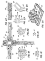
- Figs. 18 to 22 illustrate a set of assembly elements which are complementary to the elements described above. These are connecting profiles intended to ensure a fairly stable and tightly closed assembly between the ends of two, three or four partitions formed by panels 1, in particular removable vertical partitions, installed in premises.
- Figs. 18, 19 and 20 show profiles of link 52, 53 and 54 having respectively four, two and three interlocking profiles 55 intended to connect the ends of the partition forming angles of 90 °, 180 ° or 120 °.
- Each profile 55 is formed by two parallel branches 56 which are flat on the outside and which are provided on the inside with respective ribs 57 opposite one another, defining a recess 58 with a T profile.
- FIG. 21 shows in section an additional section 60 with an H section, which can be inserted into a socket profile 55 to close it, in order to ensure a pleasant appearance when no partition is connected to this socket.
- the sections 52 and 54 each have a central channel 61, 62 in which one can place, for example, a rod for fixing to the ground or electric cables.
- Fig. 22 shows how profiles 52, 53 and 60 are used, in combination with T-shaped connecting elements 35, to join the ends of different walls formed from panels 1. It is noted that the ends of the panels 1 are embedded between the edges free branches 56 of the interlocking profiles, which ensures both sufficiently rigid lateral support and a pleasant appearance. It is understood that the use of connecting profiles 52 to 54, as well as similar profiles to simply form an angle between two partitions, allows great freedom in choosing the layout of the partitions in plan.
- the partitions can have various heights, for example on either side of a profile 53.
- connection profile 65 illustrated in fig. 23 is intended to connect an edge of a horizontal partition to the top of a vertical partition. It consists of a female interlocking profile 66, similar to that of the panels 1 and intended to fit onto the male profile of the edge 4 of these panels (fig. 2), and of a male interlocking profile 67 arranged to fit into the female profile of the panels.
- the profile 67 is similar to that of the upper closure element 25 illustrated in FIGS. 4 to 6.
- connection profile 68 operating in the same way as profile 65, but having interlocking profiles 66 and 67 which form an angle of 1350 between them instead of 90 °, in order to connect a vertical wall to a wall inclined at 45 °. It goes without saying that a whole assortment of connection profiles of the same kind can be created, formed by different combinations of male or female interlocking profiles to assemble the corresponding edges of the panels 1, while the ends of the panels can be assembled as shown in fig. 22.
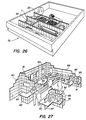
- Fig. 25 shows an example of a construction being carried out by means of modular elements according to FIGS. 1 to 15, in the form of small elements that the user can easily fold, cut or break on their sections of least resistance.
- This is a construction set using simply vertical panels 1, closure profiles 25 and 30, as well as assembly elements not shown, to create a set of partitions which can have different heights and have windows. 70.
- the same modular elements 1, 25, 30 are used to form partitions delimiting different compartments "on measure "inside a drawer 72, to accommodate objects of different sizes, for example pens, staples, notepads etc. in an office, various utensils in a kitchen, or even hardware in Not only can the user choose the layout of the partitions at will, but he can also easily modify them later.
- Fig. 27 shows an example of exhibition stands comprising different vertical walls 80 to 88 formed of modular elements according to the present invention, assembled by interlocking.
- such walls are removable, but the same elements can be used for permanent walls, for example if the interlockings are filled with an adhesive or a jointing mass.
- some of the walls support horizontal trays 90 to 93, as well as advertising or decoration panels 94 to 96 applied to the walls.
- the present invention is not limited to the exemplary embodiments described above, but it extends to all modifications or variants obvious to a person skilled in the art.
- the field of application of the modular assemblies according to the invention is very vast, since it includes in particular the fields of furniture, shopping, toys, construction of buildings, arrangement of premises, etc.
Landscapes
- Engineering & Computer Science (AREA)
- Architecture (AREA)
- Civil Engineering (AREA)
- Structural Engineering (AREA)
- Electromagnetism (AREA)
- Physics & Mathematics (AREA)
- Assembled Shelves (AREA)
- Details Of Rigid Or Semi-Rigid Containers (AREA)
- Connection Or Junction Boxes (AREA)
- Toys (AREA)
- Refuge Islands, Traffic Blockers, Or Guard Fence (AREA)
- Installation Of Indoor Wiring (AREA)
- Joining Of Building Structures In Genera (AREA)
- Structure Of Telephone Exchanges (AREA)
- Residential Or Office Buildings (AREA)
Claims (16)
- Satz von zusammensteckbaren Modulelementen zum Bau von Trennwänden, insbesondere von demontierbaren Trennwänden, die Abteile in einem Raum oder in einem Behälter bilden, bestehend aus Paneelen mit zwei gegenüberliegenden, im wesentlichen ebenen und rechtwinkligen Außenseiten, und Verbindungseinrichtungen, um die Paneelen untereinander durch Zusammenstecken zu verbinden, wobei jede der Paneelen mit zwei Längsrändern (3,4) versehen ist, von denen im Querschnitt der eine einen Zusammensteckquerschnitt mit Nut und der andere einen entsprechenden Querschnitt mit Feder aufweist, damit man ihn in den nutartigen Querschnitt eines benachbarten Elementes stecken kann,
dadurch gekennzeichnet, daß die Verbindungseinrichtungen darüberhinaus in jedem Paneel (1) eine Längsaussparung (16) aufweisen, die sich im Mittelbereich der Paneeldicke befindet, offen an einem der beiden Längsränder (3, 4) und an den zwei Paneelenden, sowie seitliche Nuten (18a), die in quer zu den Längsrändern liegenden Ebenen in gleichmäßigen Abständen angeordnet sind und eine Verbindung zwischen der Längsaussparung und den Außenseiten des Paneels (1) herstellen, und daß die Verbindungseinrichtungen außerdem Verbindungselemente (35,40,44) aufweisen, die mindestens zwei rechtwinklige Querschnitte in L- oder T-Form haben, wobei jeder dieser Querschnitte so ausgebildet ist, daß er sich gleichzeitig in die Längsaussparung (16) eines Paneels und in mindestens eine der seitlichen, in diese Aussparung mündenden Nuten (18a) einschieben läßt. - Modulelementesatz nach Anspruch 1,
dadurch gekennzeichnet, daß die Längsaussparung (16) im Längsrand (4) federartig offen ist, und daß der federartige Querschnitt (6) zwei im wesentlichen parallele Schenkel (9a, 10a) aufweist, die in Bezug auf die jeweiligen Paneelaußenflächen zurückgesetzt angeordnet sind, wobei jeder dieser Schenkel von der entsprechenden Außenfläche des Paneels (1) durch eine Schulter (9b,10b) abgesetzt ist, die einen Anschlag für den nutartigen Querschnitt (5) bildet. - Modulelementesatz nach Anspruch 2,
dadurch gekennzeichnet, daß der nutartige Querschnitt (5) zwei im wesentlichen parallele Außenschenkel (7,8) aufweist, die so ausgeführt sind, daß man sie außen auf den federartigen Querschnitt aufschieben und an der Schulter (9b,10b) anschlagen lassen kann, und mit einem Mittelsteg (15), der so ausgeführt ist, daß er sich zwischen die zwei Schenkel des federartigen Querschnitts schiebt. - Modulelementesatz nach Anspruch 3,
dadurch gekennzeichnet, daß die Außenschenkel (7,8) des nutartigen Querschnitts Vorsprünge (11,12) aufweisen, die sich in die entsprechenden Vertiefungen (13,14) des federartigen Querschnitts einlegen, um die ineinandergesteckten Querschnitte festzuhalten. - Modulelementesatz nach Anspruch 3,
gekennzeichnet durch Abschlußprofile (30), die einen nutartigen Querschnitt haben, der so ausgeführt ist, daß er sich auf den mit federartigem Querschnitt ausgeführten Rand der Paneele (1) schieben läßt, um diesen Rand zu verschließen. - Modulelementesatz nach Anspruch 3,
gekennzeichnet durch Abschlußprofile (25), die einen federartigen Steckquerschnitt aufweisen, der so ausgeführt ist, daß er sich auf den mit nutartigem Querschnitt ausgeführten Rand der Paneele (1) schieben läßt, um den Rand zu verschließen. - Modulelementesatz nach Anspruch 1,
dadurch gekennzeichnet, daß die aufeinanderfolgenden seitlichen Nuten (18a) abwechselnd auf einer Außenseite eines Paneels (1) und auf der gegenüberliegenden Außenseite münden. - Modulelementesatz nach Anspruch 7,
dadurch gekennzeichnet, daß die Verbindungselemente mindestens ein Längsverbindungselement (40) aufweisen, gebildet aus einer Platte, die so ausgeführt ist, daß sie in die Längsaussparung (16) von zwei in gegenseitiger Verlängerung angeordneten Paneelen (1) einbaubar ist, wobei die Platte parallele seitliche Rippen (41) in gleichmäßigem Abstand aufweist, die abwechselnd auf der einen bzw. auf der gegenüberliegenden Seite der Platte angeordnet sind, damit sie sich in bestimmte seitliche Nuten (18a) der Paneele einlegen lassen. - Modulelementesatz nach Anspruch 7,
dadurch gekennzeichnet, daß die Verbindungselemente mindestens ein Winkelverbindungselement (44) aufweisen, das aus einer rechtwinklig gebogenen Platte gebildet ist, die so ausgeführt ist, daß sie in die Längsaussparung (16) von zwei senkrecht stehenden Paneelen (1) einsteckbar ist, wobei die Platte parallele seitliche Rippen aufweist, die dazu dienen, sich in einige der seitlichen Nuten der zwei Paneelen einzufügen. - Modulelementesatz nach Anspruch 7,
dadurch gekennzeichnet, daß die Verbindungselemente mindestens ein T-förmiges Verbindungselement (35) aufweisen, das aus einer Platte besteht, die so ausgeführt ist, daß sie sich in die Längsaussparungen (16) eines Paneels (1) schieben läßt, wobei die Platte einen T-förmigen Querschnitt (36) an einem ihrer Enden aufweist und in der Nähe ihres anderen Endes eine seitliche Rippe (37) vorgesehen ist, die so ausgeführt ist, daß sie sich in eine seitliche Nut (18a) des Paneels einlegen läßt. - Modulelementesatz nach Anspruch 1,
dadurch gekennzeichnet, daß die Paneelen (1) Querschnitte mit geringerer Festigkeit aufweisen, die in gleichmäßigen Abständen zueinander angeordnet sind. - Modulelementesatz nach den Ansprüchen 5 und 6,
dadurch gekennzeichnet, daß die Abschlußprofile (25,30) Querschnitte mit geringerer Festigkeit aufweisen, die in gleichmäßigen Abständen zueinander angeordnet sind. - Modulelementesatz nach Anspruch 11 oder 12,
dadurch gekennzeichnet, daß die Querschnitte mit geringerer Festigkeit durch querverlaufende Schlitze (18,28,34) festgelegt sind, die über den größeren Teil des Querschnittes des Paneels oder des Profiles verlaufen. - Modulelementesatz nach Anspruch 13,
dadurch gekennzeichnet, daß sich jeder in den Paneelen (1) angebrachte Schlitz (18) in der Mitte einer seitlichen Nut (18a) befindet. - Modulelementsatz nach Anspruch 10,
gekennzeichnet durch Verbindungsformteile (52,53,54), wobei jedes Verbindungsformteil mehrere T-förmige Einsteckquerschnitte (55) aufweist, um es mittels des T-förmigen Montageelementes (35) an Enden der Paneelen (1) zu montieren. - Modulelementesatz nach Anspruch 1,
gekennzeichnet durch Verbindungsformteile (65,68), wobei jedes Verbindungsformteil mindestens zwei federartige oder nutartige Steckquerschnitte (66,67) aufweist, die in unterschiedlichen Ebenen angeordnet und so ausgeführt sind, daß sie auf die Längsränder der Paneele steckbar sind, um zwischen ihnen einen vertikalen Winkel zu bilden.
Applications Claiming Priority (3)
| Application Number | Priority Date | Filing Date | Title |
|---|---|---|---|
| FR8907927 | 1989-06-12 | ||
| FR8907927A FR2648213B1 (fr) | 1989-06-12 | 1989-06-12 | Ensemble d'elements modulaires emboitables pour la construction de cloisons |
| PCT/CH1990/000141 WO1990015906A1 (fr) | 1989-06-12 | 1990-06-06 | Ensemble d'elements modulaires emboitables pour la construction de cloisons |
Publications (2)
| Publication Number | Publication Date |
|---|---|
| EP0431100A1 EP0431100A1 (de) | 1991-06-12 |
| EP0431100B1 true EP0431100B1 (de) | 1996-03-06 |
Family
ID=9382740
Family Applications (1)
| Application Number | Title | Priority Date | Filing Date |
|---|---|---|---|
| EP90908181A Expired - Lifetime EP0431100B1 (de) | 1989-06-12 | 1990-06-06 | Satz von sich ineinanderfügenden modulelementen zum bau von trennwänden |
Country Status (9)
| Country | Link |
|---|---|
| EP (1) | EP0431100B1 (de) |
| AT (1) | ATE135070T1 (de) |
| AU (1) | AU5733190A (de) |
| DE (1) | DE69025714T2 (de) |
| DK (1) | DK0431100T3 (de) |
| ES (1) | ES2084697T3 (de) |
| FR (1) | FR2648213B1 (de) |
| WO (1) | WO1990015906A1 (de) |
| ZA (1) | ZA904548B (de) |
Cited By (1)
| Publication number | Priority date | Publication date | Assignee | Title |
|---|---|---|---|---|
| US8397937B2 (en) | 2007-07-20 | 2013-03-19 | Kardex Produktion Deutschland Gmbh | Article carrier with a dividing arrangement |
Families Citing this family (5)
| Publication number | Priority date | Publication date | Assignee | Title |
|---|---|---|---|---|
| GB0300918D0 (en) * | 2003-01-15 | 2003-02-12 | Urban Jackson Sean P D | Multi-functional display panel combining interlocking panel couplings |
| FR2977618B1 (fr) * | 2011-07-05 | 2014-03-21 | Ekrin | Palissade modulable |
| WO2020100058A1 (en) * | 2018-11-14 | 2020-05-22 | Codi - Comércio Design Industrial, Lda | Fitting system |
| GB202016737D0 (en) * | 2020-10-22 | 2020-12-09 | Swiftec Global Ltd | Modular partition system and method of manufacture thereof |
| EP4015056B1 (de) | 2020-12-16 | 2024-07-24 | Wardeblo Oü | Ineinandergreifender modulare block |
Family Cites Families (5)
| Publication number | Priority date | Publication date | Assignee | Title |
|---|---|---|---|---|
| FR460751A (fr) * | 1913-07-25 | 1913-12-11 | Alfred Herbert Gibson | Mode et dispositif de division et de subdivision des tiroirs, boites, nécessaires, tablettes et autres réceptacles |
| US4186539A (en) * | 1978-02-09 | 1980-02-05 | United Mcgill Corporation | Interlocking modular building panel with sealing strip |
| DE2857450C2 (de) * | 1978-08-21 | 1982-05-06 | Kurt 7050 Waiblingen Gassler | Vorrichtung zur lösbaren Steckverbindung von Wandteilen, insbesondere im Messebau, Ladenbau, bei der Herstellung von Möbeln, Raumteilern, Trennwänden u.dgl. |
| US4258856A (en) * | 1978-09-22 | 1981-03-31 | Marling Douglas S | Space dividing assembly |
| DE3447330A1 (de) * | 1984-12-24 | 1986-07-10 | Hoesch Ag, 4600 Dortmund | Wand- oder dachelement aus einem schaumstoffkern und metallischen deckschichten |
-
1989
- 1989-06-12 FR FR8907927A patent/FR2648213B1/fr not_active Expired - Lifetime
-
1990
- 1990-06-06 AT AT90908181T patent/ATE135070T1/de not_active IP Right Cessation
- 1990-06-06 DK DK90908181.2T patent/DK0431100T3/da active
- 1990-06-06 DE DE69025714T patent/DE69025714T2/de not_active Expired - Fee Related
- 1990-06-06 ES ES90908181T patent/ES2084697T3/es not_active Expired - Lifetime
- 1990-06-06 AU AU57331/90A patent/AU5733190A/en not_active Abandoned
- 1990-06-06 EP EP90908181A patent/EP0431100B1/de not_active Expired - Lifetime
- 1990-06-06 WO PCT/CH1990/000141 patent/WO1990015906A1/fr not_active Ceased
- 1990-06-12 ZA ZA904548A patent/ZA904548B/xx unknown
Cited By (1)
| Publication number | Priority date | Publication date | Assignee | Title |
|---|---|---|---|---|
| US8397937B2 (en) | 2007-07-20 | 2013-03-19 | Kardex Produktion Deutschland Gmbh | Article carrier with a dividing arrangement |
Also Published As
| Publication number | Publication date |
|---|---|
| FR2648213B1 (fr) | 1991-09-20 |
| ATE135070T1 (de) | 1996-03-15 |
| ZA904548B (en) | 1991-03-27 |
| FR2648213A1 (fr) | 1990-12-14 |
| ES2084697T3 (es) | 1996-05-16 |
| DK0431100T3 (da) | 1996-07-22 |
| WO1990015906A1 (fr) | 1990-12-27 |
| DE69025714D1 (de) | 1996-04-11 |
| AU5733190A (en) | 1991-01-08 |
| DE69025714T2 (de) | 1996-09-26 |
| EP0431100A1 (de) | 1991-06-12 |
Similar Documents
| Publication | Publication Date | Title |
|---|---|---|
| EP0174257B1 (de) | System aus Holzelementen für Bausatzmöbel | |
| FR2779210A1 (fr) | Systeme de construction de panneau modulaire | |
| EP0106734A1 (de) | Gerüstbildende Vorrichtung für ein Möbelstück zum Einräumen, beispielsweise ein Regal | |
| FR2517187A1 (fr) | Caisson demontable a usage de meuble | |
| EP0187100A1 (de) | Einheit von Konstruktionselementen zum Bau von Räumlichkeiten für Ausstellungen, zum Wohnen oder geeignet für andere Verwendungszwecke | |
| EP0172111A1 (de) | Winkelstütze für eine Ablage, Verkleidung usw. und daraus gebautes Möbel | |
| CH657171A5 (fr) | Plafond suspendu a grille et element allonge pour ce plafond. | |
| EP0431100A1 (de) | Satz von sich ineinanderfügenden modulelementen zum bau von trennwänden. | |
| FR2520785A1 (fr) | Bloc ou brique en treillis, compose d'elements modulaires en tole d'acier estampee et incorporant des moyens de jonction | |
| EP2065529A1 (de) | Verbundständer für die Erstellung einer Trennwand und einen solchen Ständer umfassende Trennwand | |
| FR2679939A1 (fr) | Panneau monobloc pour cloison amovible a joints creux ou plats, cloison correspondante et son procede de pose. | |
| FR2714803A1 (fr) | Etagère à piliers rigidifiants. | |
| FR2578298A1 (fr) | Elements assemblables pour la realisation de meubles de rangement | |
| FR2586732A1 (fr) | Ensemble de construction pour la realisation de cloisons ou de parois modulaires | |
| EP1944242B1 (de) | Ordnungskasten | |
| FR2466964A1 (fr) | Casier de rangement, parallelepipedique, en matiere flexible | |
| WO2014096577A1 (fr) | Caisson de meuble | |
| FR2754992A1 (fr) | Profile angulaire multifonctions reunissant les montants de mobilier | |
| FR3092007A1 (fr) | Jeu de construction | |
| EP0072333A1 (de) | Verfahren zur Herstellung von vollen und steifen Wandelementen | |
| CH642525A5 (fr) | Procede de fabrication de meubles a assemblage par profiles et meuble obtenu. | |
| FR2957617A1 (fr) | Element de construction du genre panneau et construction formee par assemblage desdits elements de construction | |
| EP2816165A1 (de) | Bausatz für Gartenhaus | |
| FR3048442A1 (fr) | Pilier ou poteau adapte a recevoir des parois, panneaux ou similaires, par exemple pour des clotures, ou pour des meubles | |
| EP0141699A2 (de) | Baukastensystem zum Errichten von Ausstellungsständen |
Legal Events
| Date | Code | Title | Description |
|---|---|---|---|
| PUAI | Public reference made under article 153(3) epc to a published international application that has entered the european phase |
Free format text: ORIGINAL CODE: 0009012 |
|
| AK | Designated contracting states |
Kind code of ref document: A1 Designated state(s): AT BE CH DE DK ES FR GB IT LI LU NL SE |
|
| 17P | Request for examination filed |
Effective date: 19910126 |
|
| 17Q | First examination report despatched |
Effective date: 19950810 |
|
| GRAA | (expected) grant |
Free format text: ORIGINAL CODE: 0009210 |
|
| AK | Designated contracting states |
Kind code of ref document: B1 Designated state(s): AT BE CH DE DK ES FR GB IT LI LU NL SE |
|
| REF | Corresponds to: |
Ref document number: 135070 Country of ref document: AT Date of ref document: 19960315 Kind code of ref document: T |
|
| REF | Corresponds to: |
Ref document number: 69025714 Country of ref document: DE Date of ref document: 19960411 |
|
| REG | Reference to a national code |
Ref country code: CH Ref legal event code: NV Representative=s name: CABINET MOSER & CIE., CONSEILS EN PROPRIETE INDUST |
|
| ITF | It: translation for a ep patent filed | ||
| REG | Reference to a national code |
Ref country code: ES Ref legal event code: FG2A Ref document number: 2084697 Country of ref document: ES Kind code of ref document: T3 |
|
| GBT | Gb: translation of ep patent filed (gb section 77(6)(a)/1977) |
Effective date: 19960430 |
|
| REG | Reference to a national code |
Ref country code: DK Ref legal event code: T3 |
|
| PLBE | No opposition filed within time limit |
Free format text: ORIGINAL CODE: 0009261 |
|
| STAA | Information on the status of an ep patent application or granted ep patent |
Free format text: STATUS: NO OPPOSITION FILED WITHIN TIME LIMIT |
|
| 26N | No opposition filed | ||
| EUG | Se: european patent has lapsed | ||
| REG | Reference to a national code |
Ref country code: GB Ref legal event code: IF02 |
|
| PGFP | Annual fee paid to national office [announced via postgrant information from national office to epo] |
Ref country code: DK Payment date: 20050627 Year of fee payment: 16 |
|
| PGFP | Annual fee paid to national office [announced via postgrant information from national office to epo] |
Ref country code: BE Payment date: 20050630 Year of fee payment: 16 Ref country code: NL Payment date: 20050630 Year of fee payment: 16 |
|
| PGFP | Annual fee paid to national office [announced via postgrant information from national office to epo] |
Ref country code: LU Payment date: 20050701 Year of fee payment: 16 |
|
| PGFP | Annual fee paid to national office [announced via postgrant information from national office to epo] |
Ref country code: ES Payment date: 20050706 Year of fee payment: 16 |
|
| PGFP | Annual fee paid to national office [announced via postgrant information from national office to epo] |
Ref country code: GB Payment date: 20050713 Year of fee payment: 16 |
|
| PG25 | Lapsed in a contracting state [announced via postgrant information from national office to epo] |
Ref country code: GB Free format text: LAPSE BECAUSE OF NON-PAYMENT OF DUE FEES Effective date: 20060606 |
|
| PG25 | Lapsed in a contracting state [announced via postgrant information from national office to epo] |
Ref country code: ES Free format text: LAPSE BECAUSE OF NON-PAYMENT OF DUE FEES Effective date: 20060607 |
|
| PGFP | Annual fee paid to national office [announced via postgrant information from national office to epo] |
Ref country code: AT Payment date: 20060629 Year of fee payment: 17 Ref country code: SE Payment date: 20060629 Year of fee payment: 17 |
|
| PG25 | Lapsed in a contracting state [announced via postgrant information from national office to epo] |
Ref country code: BE Free format text: LAPSE BECAUSE OF NON-PAYMENT OF DUE FEES Effective date: 20060630 Ref country code: DK Free format text: LAPSE BECAUSE OF NON-PAYMENT OF DUE FEES Effective date: 20060630 |
|
| PGFP | Annual fee paid to national office [announced via postgrant information from national office to epo] |
Ref country code: IT Payment date: 20060630 Year of fee payment: 17 |
|
| PGFP | Annual fee paid to national office [announced via postgrant information from national office to epo] |
Ref country code: DE Payment date: 20060708 Year of fee payment: 17 |
|
| PG25 | Lapsed in a contracting state [announced via postgrant information from national office to epo] |
Ref country code: NL Free format text: LAPSE BECAUSE OF NON-PAYMENT OF DUE FEES Effective date: 20070101 |
|
| REG | Reference to a national code |
Ref country code: DK Ref legal event code: EBP |
|
| GBPC | Gb: european patent ceased through non-payment of renewal fee |
Effective date: 20060606 |
|
| NLV4 | Nl: lapsed or anulled due to non-payment of the annual fee |
Effective date: 20070101 |
|
| REG | Reference to a national code |
Ref country code: ES Ref legal event code: FD2A Effective date: 20060607 |
|
| BERE | Be: lapsed |
Owner name: *WABA SYSTEM A.G. Effective date: 20060630 |
|
| EUG | Se: european patent has lapsed | ||
| PG25 | Lapsed in a contracting state [announced via postgrant information from national office to epo] |
Ref country code: AT Free format text: LAPSE BECAUSE OF NON-PAYMENT OF DUE FEES Effective date: 20070606 |
|
| PGFP | Annual fee paid to national office [announced via postgrant information from national office to epo] |
Ref country code: CH Payment date: 20071231 Year of fee payment: 18 |
|
| PG25 | Lapsed in a contracting state [announced via postgrant information from national office to epo] |
Ref country code: DE Free format text: LAPSE BECAUSE OF NON-PAYMENT OF DUE FEES Effective date: 20080101 |
|
| PG25 | Lapsed in a contracting state [announced via postgrant information from national office to epo] |
Ref country code: SE Free format text: LAPSE BECAUSE OF NON-PAYMENT OF DUE FEES Effective date: 20070607 |
|
| PG25 | Lapsed in a contracting state [announced via postgrant information from national office to epo] |
Ref country code: LU Free format text: LAPSE BECAUSE OF NON-PAYMENT OF DUE FEES Effective date: 20060606 |
|
| PGFP | Annual fee paid to national office [announced via postgrant information from national office to epo] |
Ref country code: FR Payment date: 20071231 Year of fee payment: 18 |
|
| REG | Reference to a national code |
Ref country code: CH Ref legal event code: PL |
|
| REG | Reference to a national code |
Ref country code: FR Ref legal event code: ST Effective date: 20090228 |
|
| PG25 | Lapsed in a contracting state [announced via postgrant information from national office to epo] |
Ref country code: LI Free format text: LAPSE BECAUSE OF NON-PAYMENT OF DUE FEES Effective date: 20080630 Ref country code: CH Free format text: LAPSE BECAUSE OF NON-PAYMENT OF DUE FEES Effective date: 20080630 |
|
| PG25 | Lapsed in a contracting state [announced via postgrant information from national office to epo] |
Ref country code: FR Free format text: LAPSE BECAUSE OF NON-PAYMENT OF DUE FEES Effective date: 20080630 |
|
| PG25 | Lapsed in a contracting state [announced via postgrant information from national office to epo] |
Ref country code: IT Free format text: LAPSE BECAUSE OF NON-PAYMENT OF DUE FEES Effective date: 20070606 |