EP0431338A2 - Farbaufzeichnungsgerät - Google Patents
Farbaufzeichnungsgerät Download PDFInfo
- Publication number
- EP0431338A2 EP0431338A2 EP90121374A EP90121374A EP0431338A2 EP 0431338 A2 EP0431338 A2 EP 0431338A2 EP 90121374 A EP90121374 A EP 90121374A EP 90121374 A EP90121374 A EP 90121374A EP 0431338 A2 EP0431338 A2 EP 0431338A2
- Authority
- EP
- European Patent Office
- Prior art keywords
- ink
- shutter
- pressure
- recording apparatus
- electrodes
- Prior art date
- Legal status (The legal status is an assumption and is not a legal conclusion. Google has not performed a legal analysis and makes no representation as to the accuracy of the status listed.)
- Granted
Links
Images





Classifications
-
- B—PERFORMING OPERATIONS; TRANSPORTING
- B41—PRINTING; LINING MACHINES; TYPEWRITERS; STAMPS
- B41J—TYPEWRITERS; SELECTIVE PRINTING MECHANISMS, i.e. MECHANISMS PRINTING OTHERWISE THAN FROM A FORME; CORRECTION OF TYPOGRAPHICAL ERRORS
- B41J2/00—Typewriters or selective printing mechanisms characterised by the printing or marking process for which they are designed
- B41J2/005—Typewriters or selective printing mechanisms characterised by the printing or marking process for which they are designed characterised by bringing liquid or particles selectively into contact with a printing material
- B41J2/01—Ink jet
- B41J2/015—Ink jet characterised by the jet generation process
- B41J2/02—Ink jet characterised by the jet generation process generating a continuous ink jet
- B41J2/025—Ink jet characterised by the jet generation process generating a continuous ink jet by vibration
Definitions
- the present invention relates to an ink recording apparatus for use in printers or the like.
- the word recording herein used refers to the fact that any desired patterns of characters, symbols, or the like are written down onto a printed material such as paper with ink jetted out by an apparatus of the present invention.
- ink jet system In conventional ink recording apparatus that are currently used in printers featuring their compactness suitable for office or personal use thereof, two types of ink jet system described below are mainly employed.
- One of the types is a piezoelectric type in which the ink is applied by piezoelectric elements within a ink chamber.
- Another type is a thermal type in which the ink generates bubbles by utilization of exoergic of heating elements within a ink chamber.
- the piezoelectric type controls diameter of ink droplets well, however, to arrange the piezoelectric elements in high density is so difficult that the ink jet head is forced to become large size. Accordingly, it is impossible for an ink jet head to discharge many ink droplets simultaneously. Then, the ink jet head is required to move for recording many dots. The result is that the ink jet head takes a long time to record a predetermined size image from the overall point of view of the recording speed, even if the frequency of ink droplet discharge can be increased within a feasible range. And also, the moving mechanism for the ink jet head is required, which prevents the ink recording apparatus from increasing its compact and lightweight performance, its quite performance and decreasing demanded power and cost.
- the recording speed of thermal type can be increased enough, because a line head can be manufactured easily by substantially integrating the heating elements.
- it needs an independent ink chamber and a nozzle for each heating element.
- the thermal type ink recording apparatus having such structure requires a high work precision in manufacturing thereof.
- the work precision and positional precision between a substrate provided with the thermal elements and the ink chambers have effect on ink jet amount so that not only the control of ink droplet diameter and also the manufacturing of head becomes difficult accompanying a cost up.
- the integrating yield of heating elements does not reach the practical level, its cost becomes enormous actually.
- a conventional ink recording apparatus is shown in the Japanese magazine "Nikkei Mechanical", issued on May 29, 1989, pp. 90 to 91, the apparatus exemplifying such ink recording apparatus that solves such problems as described above.
- Fig. 14 shows a construction of such a conventional ink recording apparatus.
- a slit plate 1 is provided with a plurality of slits 2 having a width of 50 ⁇ m and a length of 8 mm in place of nozzles.
- the slit plate 1 has also a plurality of auxiliary holes 3 equal in number to a plurality of heating elements 5 formed on a base plate 4, with an ink reservoir 6 as well provided to the slit plate.
- On the base plate 4 there are formed a plurality of electrodes 7 in correspondence to the heating elements 5 and moreover a plurality of fluid resistance elements 8 shaped into a long, narrow protrusion.
- a spacer 9 which in conjunction with the slit plate 1 and base plate 4 defines a portion serving as an ink chamber 11 illustrated in Figs. 15a to 15d.
- an ink tank 10 Under the base plate 4 there is provided an ink tank 10, whereon all the units are piled up to make up a head.
- the heating elements 5 is formed by piling up a glass layer, resistors, electrodes, and a protective coat on the base plate 4, as in a common thermal head.
- a conventional ink recording apparatus having a construction as described above will jet ink droplets while taking steps as shown in Figs. 15a to 15d. Each step is detailed below:
- the fluid resistance elements 8 provided between adjoining heating elements 5, 5, as shown in Fig. 14 will serve to prevent pressure waves from being horizontally propagated while the bubbles are being produced, thereby allowing the ink droplets 14 to be formed and jetted out without being adversely affected by such pressure waves.
- the auxiliary holes 3 provided to the slit plate 1 will absorb the pressure waves, so that pressure waves may be prevented also from being reflected.
- the heating elements 5 must eventually be used in the apparatus, that does not lead the cost of ink jet head to a substantial reduction, and since the heating elements 5 need cooling, the recording speed is not increased substantially. Further, during the alternating between a heating and cooling under the condition in which the heating elements 5 are wetted with ink, the burnt ink is caused to adhere to the surface of heating elements 5, then the growth of the burnt ink changes gradually the initial ink jet performance, and an inferior recording occurs finally.
- the ink in order for the ink to generate the pressure and transmit the pressure to the slits 2, the ink is preferably of a type easy to evaporate and also low in viscosity enough to transmit the pressure faithfully at minimized loss.
- the ink droplets 14 jetted through the slits 2 in order for the ink droplets 14 jetted through the slits 2 to fix on the recording paper (not shown), the ink is preferably of a type hard to dry to avoid any possible clogging in the slits 2 and high in viscosity enough to stabilize the jet of ink travelling toward the recording paper and also to avoid any possible running of ink.
- the ink recording apparatus of prior art is forced to sacrifice at least one of the three performance elements, that is the lifetime of the heating elements 5, the generating sensitivity of the bubbles 12 and the recording quality. Further, the apparatus needs its own recording paper in which the ink hard to run. These factors increase not only initial cost but also running cost of the apparatus.
- an essential object of the present invention is to provide an ink recording apparatus which is low in cost, compact in size, light in weight, quiet in operation thereof, superior in durability, superior in recording quality without running of ink, free to select type of recording paper, able to design the best type of ink for the apparatus, and of high reliability.
- an ink chamber for reserving ink
- an ink jet port provided to said ink chamber
- pressure-applying means for applying pressure to the ink in said ink chamber
- a shutter provided in the vicinity of said ink jet port, said shutter being movable between a shut-off position for preventing ink from being jetted out after passing through said ink jet port and a passing position for allowing ink to be jetted through
- shutter driving means for driving said shutter in response to recording signals.
- the shutter disposed in the vicinity of the ink jet port make it possible to record dots under the mechanical control of the shutters movement between the shut-off position and passing position thereof.
- the ink recording apparatus according to the invention is lighter in weight, more compact in scale and lower in cost than the conventional ink recording apparatus of piezoelectric type or thermal type, moreover able to perform a high-density recording with high reliability and superiority in recording quality.
- the ink recording apparatus according to the invention makes it possible for the ink to be designed most suitably for the apparatus.
- an ink chamber for reserving ink
- an ink jet port provided to said ink chamber
- pressure-applying means for applying pressure to the ink in said ink chamber
- a shutter provided in the vicinity of said ink jet port and outside of said ink chamber, said shutter being movable between a shut-off position for preventing ink from being jetted out after passing through said ink jet port and a passing position for allowing ink to pass through
- shutter driving means for driving said shutter with responding to recording signals
- a wall provided outside of said shutter for covering an external surface of said shutter.
- the wall disposed on the rear side thereof supports the shutter to prevent the shutter from being deformed.
- the wall also prevents the internal structure of the apparatus including the shutter from being touched by hands, fingers, or other foreign matters from external, thus enhancing the reliability of the apparatus higher than of the first embodiment of the invention.
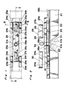
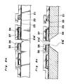
- a single-crystal silicon substrate 21 has an ink jet port 21a provided in the center thereof and an ink sump 21b provided on its side adjoining an ink chamber 20.
- the ink jet port 21a is formed as bored from the ink sump 21b through an oxide film 22 and a nitride film 23.
- a shutter 25 formed of polycrystalline-silicon has an ink passing hole 25a provided in its center and guide flots 25b, 25c provided on opposite sides thereof.
- nitride films (not shown) as lubricating layers.
- Guide pins 27b, 27c are formed also of polycrystalline-silicon.
- a front wall 28 illustrated by single dotted chain lines in Fig. 1, is integrated with the guide pins 27b, 27c, has an opening 28a provided in its center and ink recovering grooves 28b, 28c in its both ends.
- the ink chamber 20 and the ink sump 21b are charged with ink 31 composed of insulating material.
- the ink 31 is subject to working pressures corresponding to recording signals through ordinary means such as a pressure device comprising a piezoelectric element or a heating element as shown in Fig. 10, which means is not shown.
- the component parts shown in Figs. 1 to 3, as detailed later, are integrally manufactured onto the substrate 21 using semiconductor device manufacturing processes including lithography and etching.
- semiconductor device manufacturing processes including lithography and etching.
- the component parts are substantially compact in size, light in weight, and of high precision, comparable to semiconductor products. Therefore, an ink jet head in which the ink recording apparatuses of the present embodiment are integrated is manufactured without difficulty, and it is possible to select the arrangement pattern of the apparatus and/or the arrangement density of them in their integration.
- the protection plates 29, 30 shown in Fig. 2 may be manufactured by different method.
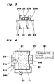
- the ink 31 is applied pressure by the pressure-applying unit 60 comprised with the piezoelectric device 60a which is driven by the piezoelectric device driving circuit 61 as shown in Fig. 4.
- the driving circuit 61 can drive the piezoelectric device 60a continuously, or intermittently, or at any timing desired so that the ink is simultaneously applied pressure.
- the pump 62 is arranged for recovering ink. The ink is recovered through the groove 28b into the ink chamber 20 by the pump 62. With respect to the groove 28c, the ink is recovered in the same manner that, however, is not shown.
- Fig. 5 is a block diagram showing a driving circuit for driving the shutter 25 of the ink recording apparatus here mentioned.
- a control circuit 141 receives a recording signal from the apparatus main body (not shown) via an input terminal 142, subsequently deciding the status of the signal to control switches 143 to 145.
- the switch 143 serves to turn on and off a power supply 146, while the switches 144 and 145 serve to control one group of connected electrodes 24a, 24b, 24e, and 24f and the other group of like electrodes 24c, 24d, 24g, and 24h, respectively, so as to render the two groups of electrodes oppositely phased. More specifically, while a voltage is applied to the side of the electrodes 24a, 24b, 24e, and 24f, the electrodes 24c, 24d, 24g, and 24h are grounded; and vice versa.
- the ink recording apparatus arranged as stated above will be explained with respect to its operation.
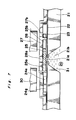
- the state thereof shown in Figs. l to 3 is such that the control circuit 141 judges the apparatus to be in ink-jetting operation according to an input signal delivered from the apparatus main body via the input terminal 142, turning on the switch 143 and activating the switches 144, 145, with the result that a voltage of several times 10 V or so is applied to the side of the electrodes 24a, 24b, 24e, and 24f.
- the shutter 25 is stably positioned as shown in the figures with its ends 25p, 25q, 25r, and 25s sucked up by virtue of electrostatic attracting force acting between the ends and the surfaces of the electrodes 24a, 24b, 24e, and 24f, where the ink passing hole 25a of the shutter 25 is aligned with the ink jet port 21a. Then, due to the pressure created within the ink chamber 20 by the pressure-applying unit 60, the ink 31 charged in the ink sump 21b passes through the ink jet port 21a and ink passing hole 25a of the shutter 25 and further through the opening 28a of the front wall 28, thus making ink droplets 32 to be jetted out.
- setting recording paper at the outside of the protection plates 29, 30 allows the ink droplets 32 to record any patterns of characters, symbols, and the like.
- the protection plates 29, 30 surrounding the shutter 25 for coverage serves to prevent operator s hands or fingers and the like from touching the shutter from external, and foreign matters from entering to the internal structure including the shutter 25.
- the control circuit 141 judges that the apparatus completed the ink-jetting operation according to an input signal delivered from the apparatus main body via the input terminal 142, changing the condition of the switches 144, 145, with a result such that a voltage is applied to the side of the electrodes 24c, 24d, 24g, and 24h.
- the shutter 25 is stably positioned in rest as having moved from the position shown in Fig.
- the shutter 25 will remain as stable in rest in the same position thereof primarily by virtue of surface force.
- the apparatus therefore even if left unused for a long period, can prevent any recording failure or any head damage.
- the protection plates 29, 30 surrounding the shutter 25 for coverage serves to prevent operator,s hands or fingers or other foreign matters from touching the shutter from external, so that the shutter 25 is not moved thereby.
- Much of the ink shut off is backed into the ink sump 21b.
- the rest part of the ink is recovered into the ink chamber 20 through the rear side of the shutter 25, the grooves 28b, 28c and pump 62, and accumulated into the ink sump 21b.
- the shutter 25 When the shutter 25 shuts the ink jet port 21a, the shutter is applied a pressure to jet the ink through the port 21a, supported by the front wall 28 in the manner that the shutter is pushed against the front wall 28. Therefore, the shutter 25 is not distorted and keeps always itself stable in its performance. That is, after shifting the shutter 25 from the state described above to the state shown in Figs. 1 to 3, to reset the shutter 25 rapidly to the state shown in Figs. 6 and 7 makes it possible to record a recording minimum unit called a dot under the condition that the ink 31 is continuously applied pressure by the pressure-applying unit 60. Then, controlling the rest time of the shutter 25 at its each rest position, the apparatus can record dots in various manners. In this case, the control circuit 141 shown in Fig. 5 has a function to manage time, it is very easy to make up such a circuit.
- the shutter 25 has two rest positions, if the electrodes 24a to 24h are increased more, the rest positions are also increased.
- the shutter may have three rest positions so that the ink passing hole of the shutter allows ink to be jetted only at the center rest position.
- the rest time of the shutter may be also controlled as described above.
- an ink-jetting mode may be set such that the ink is continuously jetted without being cut into droplets corresponding to each one dot respectively.
- the shutter is required to stop at the position where the ink passes through the ink passing hole of the shutter. Consequently, the recording quality of the apparatus will be somewhat inferior.
- the embodiment shown in Fig. 1 has no problem when the shutter 25 reciprocates at enough high speed. Comparing the embodiment with another embodiment having three rest positions with respect to number of electrodes, namely number of wires, integration efficiency, both of them are substantially equal.
- the pressure-applying unit 60 can be operated in synchronization with recording frequency, the ink 31 will not be jetted through the ink passing hole 25a during the movement of the shutter 25.
- the piezoelectric device is employed in the present embodiment, other means can be employed as a pressure-creating means instead of the device.
- the size of a dot is controllable by varying the size (volume) of an ink droplet. Therefore, an area gradation recording can be performed, and especially it is very useful for recording a picture image such that the recording quality will be substantially improved. That means an improvement of roughness with respect to an image quality, and it is very valuable.
- an ink recording apparatus which makes it possible for the ink to be designed most suitably, because the ink is jetted and shut under the mechanical control of the shutter 25 which is shifted with applying voltage to the electrodes 24a to 24h, and which can be highly reliable and superior in recording quality.
- the ink recording apparatus of the first embodiment of the present invention can be manufactured.
- the component structures are integrally manufactured using the semiconductor device manufacturing processes, thereby allowing the integrated head to be manufactured very simply and furthermore rendering them high in precision as well as steady in performance.
- the integration degree can be substantially increased by arranging the apparatuses crosswise. According technicallyly, the ink recording apparatus can be steadily mass-prcduced which features their remarkably high reliability, light weight and compactness, low cost, quietness, high-speed and high-density recording, and further high precision.
- the ink jet head is actually formed by integrating the apparatuses in high density, so the ink chamber may have generally a plurality of ink jet ports and shutters.
- FIG. 9 An example of the ink jet head in which the seven shutters 25 having an ink jet port 21a respectively are integrated in staggered fashion arrangement to one ink chamber (not shown) is shown in Fig. 9.
- the electrodes 24a to 24h are also arranged corresponding to each shutter 25.
- one pressure-applying unit and one pump are provided with the head corresponding to the one ink chamber.
- the front wall a plurality of walls may be formed corresponding to either each shutter or some shutters. Otherwise, one front wall may be formed corresponding to all shutters.
- the condition of the shutter in recording is indicated by a signal "1"
- the condition of the shutter in non-recording is indicated by a signal "0".
- each shutter 25 When each shutter 25 is controlled by the signals, a pattern of characters, symbols, and any desired pictures are able to form on a sheet of recording paper.
- the control circuits are required corresponding to each of the shutter 25, but such integration of circuit is very easy and does not become burden.
- the ink recording apparatuses of the first embodiment can be made into the integrated ink jet head described above into even the full size of A4. Further, the arrangement density of them can be enough highly enhanced by arranging them in pattern of staggered fashion.
- the diameter of the ink droplet ought to be 50 ⁇ m.
- the size of ink droplet can be substantially freely set and such diameter is easily set. Then, the printer which employes the ink jet head described above is decidedly superior in high-speed recording performance thereof to the printer according to the prior art.
- the ink jet head takes a second to record a image of size A4 under such condition that the longitudinal recording density is equal to the lateral one, each dot must be recorded within 250 micro seconds. That is, the frequency of the shutter 25 is 4KHz. Such frequency, however, is enough attained even by heating elements, the heating elements have various problems as described before.
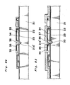
- the second embodiment of the invention can be arranged as shown in Figs. 10 to 13, wherein a single-crystal silicon substrate 41 has an ink jet port 41a provided in the center thereof and an ink sump 41b provided on its side adjoining an ink chamber 40.
- the ink jet port 41a is formed as bored from the ink sump 41b through an oxide film 42 and a nitride film 43.
- a shutter 45 formed of polycrystalline-silicon has an ink passing hole 45a provided in its center thereof.
- nitride films (not shown) as lubricating layers.
- Shaft 47 is formed also of polycrystalline-silicon, and supports the shutter 45 rotatably and also holds the shutter 45 by the upper flanged portion 47a thereof.
- the ink chamber 40 and the ink sump 41b are charged with ink 51 composed of insulating material.
- the component parts shown in Figs. 10 to 13, like the first embodiment, are integrally manufactured onto the substrate 41 using semiconductor device manufacturing processes including lithography and etching.
- the result, also like the first embodiment, is that the component parts are substantially compact in size, light in weight, and of high precision, comparable to semiconductor products. Therefore, an ink jet head in which the ink recording apparatuses of the present embodiment are integrated is manufactured without difficulty, and it is possible to select the arrangement pattern of the apparatus and/or the arrangement density of them in their integration.
- control circuit for the shutter 45 and the pressure-applying unit for the ink 51 are the same as the first embodiment.
- the ink recording apparatus arranged as stated above will be explained with respect to its operation.
- the state thereof shown in Figs. 10 and 11 is such that a voltage of several times 10 V or so is applied to the electrodes 44a and 44c.
- the shutter 45 is stably positioned as shown in the figures with its ends 45p and 45g sucked up by virtue of electrostatic attracting force acting between the ends and the surfaces of the electrodes 44a and 44c, where the ink jet port 41a of the substrate 41 is shut off by the shutter 45, so that the ink 51 charged in the ink sump 41b can not be jetted out through the ink passing hole 45a even if the ink is jetted through the ink jet port 41a due to the pressure applied to the ink.
- the shutter 25 does not allow the ink droplets to record any patterns of characters, symbols, and the like.
- the ink recording apparatus will be described in its states in which the shutter 45 has moved away from the position shown in Fig. 10.
- the control circuit judges that the apparatus completed the ink-jetting operation according to an input signal delivered from the apparatus main body via the input terminal, changing the condition of the switches with a result such that the applied voltage is changed from the electrodes 44a and 44c to the electrodes 44b and 44d.
- the shutter 45 is stably positioned in rest as having rotated about the shaft 47 in a clockwise direction from the position shown in Fig.
- setting recording paper at the outside of the shutter 45 allows the ink droplets to record any patterns of characters, symbols, and the like.
- the shutter 45 is stably positioned in rest as having rotated about the shaft 47 in a clockwise direction from the position shown in Fig. 12 with its ends 45p and 45g sucked up by virtue of electrostatic attracting force acting between the ends and the surfaces of the electrodes 44c and 44e, where the shutter 45 shuts again the ink jet port 41a.
- the shutter 25 does not allow the ink droplets to record any patterns of characters, symbols, and the like.
- the second embodiment is the same as the variation of the first embodiment having three rest positions of the shutter in operation, the second embodiment can perform the area gradation recording, too.
- the second embodiment of the present invention like as the first embodiment, it is possible to provide an ink recording apparatus which can control the jetting and shutting of the ink droplets under the mechanical control of the shutter 45 which is rotated with applying voltage to the electrodes 44a to 44e, and which can be highly reliable and superior in recording quality.
- the second embodiment may be faster than the first embodiment in the recording speed, and can be modified to an ink recording apparatus which needs neither heating elements nor piezoelectric elements (excepting means for applying pressure to whole of the ink chamber) in the ink chamber when the shutter 45 is driven with responding to recording signals.
- the front wall and protection plate are not mentioned in the explanation thereof, these elements can be easily formed as necessary.
- the electrostatic attracting force is, however, used as the driving force for the shutter, the other means of course may be used.
- the shape of the ink jet port is not required to be a circle, for example, the ink jet port may be a slit which cooperates with the ink passing hole in forming the ink droplets.
Landscapes
- Particle Formation And Scattering Control In Inkjet Printers (AREA)
- Ink Jet (AREA)
Applications Claiming Priority (2)
| Application Number | Priority Date | Filing Date | Title |
|---|---|---|---|
| JP1292899A JP2746703B2 (ja) | 1989-11-09 | 1989-11-09 | インクジェットヘッド装置及びその製造法 |
| JP292899/89 | 1989-11-09 |
Publications (3)
| Publication Number | Publication Date |
|---|---|
| EP0431338A2 true EP0431338A2 (de) | 1991-06-12 |
| EP0431338A3 EP0431338A3 (en) | 1991-10-30 |
| EP0431338B1 EP0431338B1 (de) | 1995-06-21 |
Family
ID=17787836
Family Applications (1)
| Application Number | Title | Priority Date | Filing Date |
|---|---|---|---|
| EP90121374A Expired - Lifetime EP0431338B1 (de) | 1989-11-09 | 1990-11-08 | Farbaufzeichnungsgerät |
Country Status (4)
| Country | Link |
|---|---|
| US (1) | US5200768A (de) |
| EP (1) | EP0431338B1 (de) |
| JP (1) | JP2746703B2 (de) |
| DE (1) | DE69020317T2 (de) |
Cited By (66)
| Publication number | Priority date | Publication date | Assignee | Title |
|---|---|---|---|---|
| WO1993017147A1 (en) * | 1992-02-25 | 1993-09-02 | Markpoint Development Ab | A method of coating a piezoelectric substrate with a semi-conducting material and a method of producing a droplet ejector arrangement including the coating method |
| EP0968825A1 (de) * | 1998-06-30 | 2000-01-05 | KRI International, Inc. | Zeilendruckkopf für Tintenstrahldrucker |
| EP0922582A3 (de) * | 1997-12-05 | 2000-03-15 | Canon Kabushiki Kaisha | Tintenstrahlaufzeichnungskopfherstellungsverfahren |
| EP0999934A4 (de) * | 1997-07-15 | 2001-06-27 | Silverbrook Res Pty Ltd | Thermisch betätigter tintenstrahl |
| US6746105B2 (en) | 1997-07-15 | 2004-06-08 | Silverbrook Research Pty. Ltd. | Thermally actuated ink jet printing mechanism having a series of thermal actuator units |
| US6776476B2 (en) | 1997-07-15 | 2004-08-17 | Silverbrook Research Pty Ltd. | Ink jet printhead chip with active and passive nozzle chamber structures |
| US6783217B2 (en) | 1997-07-15 | 2004-08-31 | Silverbrook Research Pty Ltd | Micro-electromechanical valve assembly |
| US6786570B2 (en) | 1997-07-15 | 2004-09-07 | Silverbrook Research Pty Ltd | Ink supply arrangement for a printing mechanism of a wide format pagewidth inkjet printer |
| US6824251B2 (en) | 1997-07-15 | 2004-11-30 | Silverbrook Research Pty Ltd | Micro-electromechanical assembly that incorporates a covering formation for a micro-electromechanical device |
| US6834939B2 (en) | 2002-11-23 | 2004-12-28 | Silverbrook Research Pty Ltd | Micro-electromechanical device that incorporates covering formations for actuators of the device |
| US6880914B2 (en) | 1997-07-15 | 2005-04-19 | Silverbrook Research Pty Ltd | Inkjet pagewidth printer for high volume pagewidth printing |
| US6880918B2 (en) | 1997-07-15 | 2005-04-19 | Silverbrook Research Pty Ltd | Micro-electromechanical device that incorporates a motion-transmitting structure |
| US6886918B2 (en) | 1998-06-09 | 2005-05-03 | Silverbrook Research Pty Ltd | Ink jet printhead with moveable ejection nozzles |
| US6886917B2 (en) | 1998-06-09 | 2005-05-03 | Silverbrook Research Pty Ltd | Inkjet printhead nozzle with ribbed wall actuator |
| US6916082B2 (en) | 1997-07-15 | 2005-07-12 | Silverbrook Research Pty Ltd | Printing mechanism for a wide format pagewidth inkjet printer |
| US6918707B2 (en) | 1997-07-15 | 2005-07-19 | Silverbrook Research Pty Ltd | Keyboard printer print media transport assembly |
| US6927786B2 (en) | 1997-07-15 | 2005-08-09 | Silverbrook Research Pty Ltd | Ink jet nozzle with thermally operable linear expansion actuation mechanism |
| US6929352B2 (en) | 1997-07-15 | 2005-08-16 | Silverbrook Research Pty Ltd | Inkjet printhead chip for use with a pulsating pressure ink supply |
| US6932459B2 (en) | 1997-07-15 | 2005-08-23 | Silverbrook Research Pty Ltd | Ink jet printhead |
| US6935724B2 (en) | 1997-07-15 | 2005-08-30 | Silverbrook Research Pty Ltd | Ink jet nozzle having actuator with anchor positioned between nozzle chamber and actuator connection point |
| US6976751B2 (en) | 1997-07-15 | 2005-12-20 | Silverbrook Research Pty Ltd | Motion transmitting structure |
| US6986613B2 (en) | 1997-07-15 | 2006-01-17 | Silverbrook Research Pty Ltd | Keyboard |
| US7004566B2 (en) | 1997-07-15 | 2006-02-28 | Silverbrook Research Pty Ltd | Inkjet printhead chip that incorporates micro-mechanical lever mechanisms |
| US7008041B2 (en) | 1997-07-15 | 2006-03-07 | Silverbrook Research Pty Ltd | Printing mechanism having elongate modular structure |
| US7008046B2 (en) | 1997-07-15 | 2006-03-07 | Silverbrook Research Pty Ltd | Micro-electromechanical liquid ejection device |
| US7022250B2 (en) | 1997-07-15 | 2006-04-04 | Silverbrook Research Pty Ltd | Method of fabricating an ink jet printhead chip with differential expansion actuators |
| US7040738B2 (en) | 1997-07-15 | 2006-05-09 | Silverbrook Research Pty Ltd | Printhead chip that incorporates micro-mechanical translating mechanisms |
| US7044584B2 (en) | 1997-07-15 | 2006-05-16 | Silverbrook Research Pty Ltd | Wide format pagewidth inkjet printer |
| US7066574B2 (en) | 1997-07-15 | 2006-06-27 | Silverbrook Research Pty Ltd | Micro-electromechanical device having a laminated thermal bend actuator |
| US7111924B2 (en) | 1998-10-16 | 2006-09-26 | Silverbrook Research Pty Ltd | Inkjet printhead having thermal bend actuator heating element electrically isolated from nozzle chamber ink |
| US7131715B2 (en) | 1997-07-15 | 2006-11-07 | Silverbrook Research Pty Ltd | Printhead chip that incorporates micro-mechanical lever mechanisms |
| US7144519B2 (en) | 1998-10-16 | 2006-12-05 | Silverbrook Research Pty Ltd | Method of fabricating an inkjet printhead chip having laminated actuators |
| US7147302B2 (en) | 1997-07-15 | 2006-12-12 | Silverbrook Researh Pty Ltd | Nozzle assembly |
| US7147305B2 (en) | 1997-07-15 | 2006-12-12 | Silverbrook Research Pty Ltd | Printer formed from integrated circuit printhead |
| US7175260B2 (en) | 2002-06-28 | 2007-02-13 | Silverbrook Research Pty Ltd | Ink jet nozzle arrangement configuration |
| US7195339B2 (en) | 1997-07-15 | 2007-03-27 | Silverbrook Research Pty Ltd | Ink jet nozzle assembly with a thermal bend actuator |
| US7207654B2 (en) | 1997-07-15 | 2007-04-24 | Silverbrook Research Pty Ltd | Ink jet with narrow chamber |
| US7240992B2 (en) | 1997-07-15 | 2007-07-10 | Silverbrook Research Pty Ltd | Ink jet printhead incorporating a plurality of nozzle arrangement having backflow prevention mechanisms |
| US7246883B2 (en) | 1997-07-15 | 2007-07-24 | Silverbrook Research Pty Ltd | Motion transmitting structure for a nozzle arrangement of a printhead chip for an inkjet printhead |
| US7246884B2 (en) | 1997-07-15 | 2007-07-24 | Silverbrook Research Pty Ltd | Inkjet printhead having enclosed inkjet actuators |
| US7252366B2 (en) | 1997-07-15 | 2007-08-07 | Silverbrook Research Pty Ltd | Inkjet printhead with high nozzle area density |
| US7267424B2 (en) | 1997-07-15 | 2007-09-11 | Silverbrook Research Pty Ltd | Wide format pagewidth printer |
| US7278711B2 (en) | 1997-07-15 | 2007-10-09 | Silverbrook Research Pty Ltd | Nozzle arrangement incorporating a lever based ink displacement mechanism |
| US7287836B2 (en) | 1997-07-15 | 2007-10-30 | Sil;Verbrook Research Pty Ltd | Ink jet printhead with circular cross section chamber |
| US7303254B2 (en) | 1997-07-15 | 2007-12-04 | Silverbrook Research Pty Ltd | Print assembly for a wide format pagewidth printer |
| US7334873B2 (en) | 2002-04-12 | 2008-02-26 | Silverbrook Research Pty Ltd | Discrete air and nozzle chambers in a printhead chip for an inkjet printhead |
| US7360872B2 (en) | 1997-07-15 | 2008-04-22 | Silverbrook Research Pty Ltd | Inkjet printhead chip with nozzle assemblies incorporating fluidic seals |
| US7381340B2 (en) | 1997-07-15 | 2008-06-03 | Silverbrook Research Pty Ltd | Ink jet printhead that incorporates an etch stop layer |
| US7401901B2 (en) | 1997-07-15 | 2008-07-22 | Silverbrook Research Pty Ltd | Inkjet printhead having nozzle plate supported by encapsulated photoresist |
| US7407269B2 (en) | 2002-06-28 | 2008-08-05 | Silverbrook Research Pty Ltd | Ink jet nozzle assembly including displaceable ink pusher |
| US7431446B2 (en) | 1997-07-15 | 2008-10-07 | Silverbrook Research Pty Ltd | Web printing system having media cartridge carousel |
| US7434915B2 (en) | 1997-07-15 | 2008-10-14 | Silverbrook Research Pty Ltd | Inkjet printhead chip with a side-by-side nozzle arrangement layout |
| US7461924B2 (en) | 1997-07-15 | 2008-12-09 | Silverbrook Research Pty Ltd | Printhead having inkjet actuators with contractible chambers |
| US7465030B2 (en) | 1997-07-15 | 2008-12-16 | Silverbrook Research Pty Ltd | Nozzle arrangement with a magnetic field generator |
| US7468139B2 (en) | 1997-07-15 | 2008-12-23 | Silverbrook Research Pty Ltd | Method of depositing heater material over a photoresist scaffold |
| US7524026B2 (en) | 1997-07-15 | 2009-04-28 | Silverbrook Research Pty Ltd | Nozzle assembly with heat deflected actuator |
| US7556356B1 (en) | 1997-07-15 | 2009-07-07 | Silverbrook Research Pty Ltd | Inkjet printhead integrated circuit with ink spread prevention |
| US7571988B2 (en) | 2000-05-23 | 2009-08-11 | Silverbrook Research Pty Ltd | Variable-volume nozzle arrangement |
| US7753463B2 (en) | 1997-07-15 | 2010-07-13 | Silverbrook Research Pty Ltd | Processing of images for high volume pagewidth printing |
| US7758142B2 (en) | 2002-04-12 | 2010-07-20 | Silverbrook Research Pty Ltd | High volume pagewidth printing |
| US7784902B2 (en) | 1997-07-15 | 2010-08-31 | Silverbrook Research Pty Ltd | Printhead integrated circuit with more than 10000 nozzles |
| US7802871B2 (en) | 1997-07-15 | 2010-09-28 | Silverbrook Research Pty Ltd | Ink jet printhead with amorphous ceramic chamber |
| US7854500B2 (en) | 1998-11-09 | 2010-12-21 | Silverbrook Research Pty Ltd | Tamper proof print cartridge for a video game console |
| US7891767B2 (en) | 1997-07-15 | 2011-02-22 | Silverbrook Research Pty Ltd | Modular self-capping wide format print assembly |
| US7967418B2 (en) | 1997-07-15 | 2011-06-28 | Silverbrook Research Pty Ltd | Printhead with nozzles having individual supply passages extending into substrate |
| US8109611B2 (en) | 2002-04-26 | 2012-02-07 | Silverbrook Research Pty Ltd | Translation to rotation conversion in an inkjet printhead |
Families Citing this family (13)
| Publication number | Priority date | Publication date | Assignee | Title |
|---|---|---|---|---|
| US6729002B1 (en) * | 1995-09-05 | 2004-05-04 | Seiko Epson Corporation | Method of producing an ink jet recording head |
| US6000787A (en) * | 1996-02-07 | 1999-12-14 | Hewlett-Packard Company | Solid state ink jet print head |
| US7527357B2 (en) | 1997-07-15 | 2009-05-05 | Silverbrook Research Pty Ltd | Inkjet nozzle array with individual feed channel for each nozzle |
| US7393083B2 (en) * | 1997-07-15 | 2008-07-01 | Silverbrook Research Pty Ltd | Inkjet printer with low nozzle to chamber cross-section ratio |
| US6302528B1 (en) * | 1997-07-15 | 2001-10-16 | Silverbrook Research Pty Ltd | Thermal actuated ink jet printing mechanism |
| US6258286B1 (en) * | 1999-03-02 | 2001-07-10 | Eastman Kodak Company | Making ink jet nozzle plates using bore liners |
| US6303042B1 (en) * | 1999-03-02 | 2001-10-16 | Eastman Kodak Company | Making ink jet nozzle plates |
| US6364460B1 (en) | 2000-06-13 | 2002-04-02 | Chad R. Sager | Liquid delivery system |
| US6629756B2 (en) | 2001-02-20 | 2003-10-07 | Lexmark International, Inc. | Ink jet printheads and methods therefor |
| SG116514A1 (en) * | 2002-11-13 | 2005-11-28 | Sony Corp | Liquid-ejecting method and liquid-ejecting apparatus. |
| US8079668B2 (en) | 2009-08-25 | 2011-12-20 | Silverbrook Research Pty Ltd | Crack-resistant thermal bend actuator |
| JP6606934B2 (ja) * | 2015-09-10 | 2019-11-20 | セイコーエプソン株式会社 | 液体噴射装置 |
| JP2017165017A (ja) * | 2016-03-17 | 2017-09-21 | セイコーエプソン株式会社 | 液体吐出装置および液体を吐出する方法 |
Family Cites Families (9)
| Publication number | Priority date | Publication date | Assignee | Title |
|---|---|---|---|---|
| US4199767A (en) * | 1979-02-21 | 1980-04-22 | International Business Machines Corporation | Nozzle valve for ink jet printers |
| US4458255A (en) * | 1980-07-07 | 1984-07-03 | Hewlett-Packard Company | Apparatus for capping an ink jet print head |
| US4367479A (en) * | 1980-11-03 | 1983-01-04 | Exxon Research And Engineering Co. | Method and apparatus for purging and/or priming an ink jet |
| JPS6179665A (ja) * | 1984-09-28 | 1986-04-23 | Toshiba Corp | オリフイス移動型インクジエツト装置 |
| JPS61242848A (ja) * | 1985-04-22 | 1986-10-29 | Ricoh Co Ltd | インクジエツト記録用シヤツタ |
| JPS62101445A (ja) * | 1985-10-29 | 1987-05-11 | Canon Inc | 記録装置 |
| JPS62156969A (ja) * | 1985-12-28 | 1987-07-11 | Canon Inc | 液体噴射記録ヘツド |
| JP2747600B2 (ja) * | 1989-03-31 | 1998-05-06 | キヤノン株式会社 | インクジェット記録装置 |
| JP2839345B2 (ja) * | 1989-09-11 | 1998-12-16 | 松下電器産業株式会社 | インク記録装置 |
-
1989
- 1989-11-09 JP JP1292899A patent/JP2746703B2/ja not_active Expired - Fee Related
-
1990
- 1990-11-08 EP EP90121374A patent/EP0431338B1/de not_active Expired - Lifetime
- 1990-11-08 DE DE69020317T patent/DE69020317T2/de not_active Expired - Fee Related
- 1990-11-09 US US07/610,967 patent/US5200768A/en not_active Expired - Fee Related
Cited By (240)
| Publication number | Priority date | Publication date | Assignee | Title |
|---|---|---|---|---|
| WO1993017147A1 (en) * | 1992-02-25 | 1993-09-02 | Markpoint Development Ab | A method of coating a piezoelectric substrate with a semi-conducting material and a method of producing a droplet ejector arrangement including the coating method |
| US5518952A (en) * | 1992-02-25 | 1996-05-21 | Markpoint Development Ab | Method of coating a piezoelectric substrate with a semiconducting material |
| US7588316B2 (en) | 1997-07-15 | 2009-09-15 | Silverbrook Research Pty Ltd | Wide format print assembly having high resolution printhead |
| US7591534B2 (en) | 1997-07-15 | 2009-09-22 | Silverbrook Research Pty Ltd | Wide format print assembly having CMOS drive circuitry |
| EP0999934A4 (de) * | 1997-07-15 | 2001-06-27 | Silverbrook Res Pty Ltd | Thermisch betätigter tintenstrahl |
| US8029107B2 (en) | 1997-07-15 | 2011-10-04 | Silverbrook Research Pty Ltd | Printhead with double omega-shaped heater elements |
| US6746105B2 (en) | 1997-07-15 | 2004-06-08 | Silverbrook Research Pty. Ltd. | Thermally actuated ink jet printing mechanism having a series of thermal actuator units |
| US6776476B2 (en) | 1997-07-15 | 2004-08-17 | Silverbrook Research Pty Ltd. | Ink jet printhead chip with active and passive nozzle chamber structures |
| US6783217B2 (en) | 1997-07-15 | 2004-08-31 | Silverbrook Research Pty Ltd | Micro-electromechanical valve assembly |
| US6786570B2 (en) | 1997-07-15 | 2004-09-07 | Silverbrook Research Pty Ltd | Ink supply arrangement for a printing mechanism of a wide format pagewidth inkjet printer |
| US6824251B2 (en) | 1997-07-15 | 2004-11-30 | Silverbrook Research Pty Ltd | Micro-electromechanical assembly that incorporates a covering formation for a micro-electromechanical device |
| US7976130B2 (en) | 1997-07-15 | 2011-07-12 | Silverbrook Research Pty Ltd | Printhead micro-electromechanical nozzle arrangement with motion-transmitting structure |
| US6840600B2 (en) | 1997-07-15 | 2005-01-11 | Silverbrook Research Pty Ltd | Fluid ejection device that incorporates covering formations for actuators of the fluid ejection device |
| US6848780B2 (en) | 1997-07-15 | 2005-02-01 | Sivlerbrook Research Pty Ltd | Printing mechanism for a wide format pagewidth inkjet printer |
| US6880914B2 (en) | 1997-07-15 | 2005-04-19 | Silverbrook Research Pty Ltd | Inkjet pagewidth printer for high volume pagewidth printing |
| US6880918B2 (en) | 1997-07-15 | 2005-04-19 | Silverbrook Research Pty Ltd | Micro-electromechanical device that incorporates a motion-transmitting structure |
| US7976129B2 (en) | 1997-07-15 | 2011-07-12 | Silverbrook Research Pty Ltd | Nozzle structure with reciprocating cantilevered thermal actuator |
| US7967416B2 (en) | 1997-07-15 | 2011-06-28 | Silverbrook Research Pty Ltd | Sealed nozzle arrangement for printhead |
| US6916082B2 (en) | 1997-07-15 | 2005-07-12 | Silverbrook Research Pty Ltd | Printing mechanism for a wide format pagewidth inkjet printer |
| US6918707B2 (en) | 1997-07-15 | 2005-07-19 | Silverbrook Research Pty Ltd | Keyboard printer print media transport assembly |
| US6921221B2 (en) | 1997-07-15 | 2005-07-26 | Silverbrook Research Pty Ltd | Combination keyboard and printer apparatus |
| US6923583B2 (en) | 1997-07-15 | 2005-08-02 | Silverbrook Research Pty Ltd | Computer Keyboard with integral printer |
| US6927786B2 (en) | 1997-07-15 | 2005-08-09 | Silverbrook Research Pty Ltd | Ink jet nozzle with thermally operable linear expansion actuation mechanism |
| US6929352B2 (en) | 1997-07-15 | 2005-08-16 | Silverbrook Research Pty Ltd | Inkjet printhead chip for use with a pulsating pressure ink supply |
| US6932459B2 (en) | 1997-07-15 | 2005-08-23 | Silverbrook Research Pty Ltd | Ink jet printhead |
| US6935724B2 (en) | 1997-07-15 | 2005-08-30 | Silverbrook Research Pty Ltd | Ink jet nozzle having actuator with anchor positioned between nozzle chamber and actuator connection point |
| US6948799B2 (en) | 1997-07-15 | 2005-09-27 | Silverbrook Research Pty Ltd | Micro-electromechanical fluid ejecting device that incorporates a covering formation for a micro-electromechanical actuator |
| US6953295B2 (en) | 1997-07-15 | 2005-10-11 | Silverbrook Research Pty Ltd | Small footprint computer system |
| US7967418B2 (en) | 1997-07-15 | 2011-06-28 | Silverbrook Research Pty Ltd | Printhead with nozzles having individual supply passages extending into substrate |
| US7942503B2 (en) | 1997-07-15 | 2011-05-17 | Silverbrook Research Pty Ltd | Printhead with nozzle face recess to contain ink floods |
| US7938509B2 (en) | 1997-07-15 | 2011-05-10 | Silverbrook Research Pty Ltd | Nozzle arrangement with sealing structure |
| US6976751B2 (en) | 1997-07-15 | 2005-12-20 | Silverbrook Research Pty Ltd | Motion transmitting structure |
| US7934803B2 (en) | 1997-07-15 | 2011-05-03 | Kia Silverbrook | Inkjet nozzle arrangement with rectangular plan nozzle chamber and ink ejection paddle |
| US7934796B2 (en) | 1997-07-15 | 2011-05-03 | Silverbrook Research Pty Ltd | Wide format printer having high speed printhead |
| US6986613B2 (en) | 1997-07-15 | 2006-01-17 | Silverbrook Research Pty Ltd | Keyboard |
| US6988841B2 (en) | 1997-07-15 | 2006-01-24 | Silverbrook Research Pty Ltd. | Pagewidth printer that includes a computer-connectable keyboard |
| US6988788B2 (en) | 1997-07-15 | 2006-01-24 | Silverbrook Research Pty Ltd | Ink jet printhead chip with planar actuators |
| US6994420B2 (en) | 1997-07-15 | 2006-02-07 | Silverbrook Research Pty Ltd | Print assembly for a wide format pagewidth inkjet printer, having a plurality of printhead chips |
| US7004566B2 (en) | 1997-07-15 | 2006-02-28 | Silverbrook Research Pty Ltd | Inkjet printhead chip that incorporates micro-mechanical lever mechanisms |
| US7008041B2 (en) | 1997-07-15 | 2006-03-07 | Silverbrook Research Pty Ltd | Printing mechanism having elongate modular structure |
| US7008046B2 (en) | 1997-07-15 | 2006-03-07 | Silverbrook Research Pty Ltd | Micro-electromechanical liquid ejection device |
| US7011390B2 (en) | 1997-07-15 | 2006-03-14 | Silverbrook Research Pty Ltd | Printing mechanism having wide format printing zone |
| US7022250B2 (en) | 1997-07-15 | 2006-04-04 | Silverbrook Research Pty Ltd | Method of fabricating an ink jet printhead chip with differential expansion actuators |
| US7032998B2 (en) | 1997-07-15 | 2006-04-25 | Silverbrook Research Pty Ltd | Ink jet printhead chip that incorporates through-wafer ink ejection mechanisms |
| US7040738B2 (en) | 1997-07-15 | 2006-05-09 | Silverbrook Research Pty Ltd | Printhead chip that incorporates micro-mechanical translating mechanisms |
| US7044584B2 (en) | 1997-07-15 | 2006-05-16 | Silverbrook Research Pty Ltd | Wide format pagewidth inkjet printer |
| US7055935B2 (en) | 1997-07-15 | 2006-06-06 | Silverbrook Research Pty Ltd | Ink ejection devices within an inkjet printer |
| US7055934B2 (en) | 1997-07-15 | 2006-06-06 | Silverbrook Research Pty Ltd | Inkjet nozzle comprising a motion-transmitting structure |
| US7055933B2 (en) | 1997-07-15 | 2006-06-06 | Silverbrook Research Pty Ltd | MEMS device having formations for covering actuators of the device |
| US7066574B2 (en) | 1997-07-15 | 2006-06-27 | Silverbrook Research Pty Ltd | Micro-electromechanical device having a laminated thermal bend actuator |
| US7066578B2 (en) | 1997-07-15 | 2006-06-27 | Silverbrook Research Pty Ltd | Inkjet printhead having compact inkjet nozzles |
| US7067067B2 (en) | 1997-07-15 | 2006-06-27 | Silverbrook Research Pty Ltd | Method of fabricating an ink jet printhead chip with active and passive nozzle chamber structures |
| US7077588B2 (en) | 1997-07-15 | 2006-07-18 | Silverbrook Research Pty Ltd | Printer and keyboard combination |
| US7083263B2 (en) | 1997-07-15 | 2006-08-01 | Silverbrook Research Pty Ltd | Micro-electromechanical fluid ejection device with actuator guide formations |
| US7083264B2 (en) | 1997-07-15 | 2006-08-01 | Silverbrook Research Pty Ltd | Micro-electromechanical liquid ejection device with motion amplification |
| US7083261B2 (en) | 1997-07-15 | 2006-08-01 | Silverbrook Research Pty Ltd | Printer incorporating a microelectromechanical printhead |
| US7922298B2 (en) | 1997-07-15 | 2011-04-12 | Silverbrok Research Pty Ltd | Ink jet printhead with displaceable nozzle crown |
| US7086709B2 (en) | 1997-07-15 | 2006-08-08 | Silverbrook Research Pty Ltd | Print engine controller for high volume pagewidth printing |
| US7922293B2 (en) | 1997-07-15 | 2011-04-12 | Silverbrook Research Pty Ltd | Printhead having nozzle arrangements with magnetic paddle actuators |
| US7097285B2 (en) | 1997-07-15 | 2006-08-29 | Silverbrook Research Pty Ltd | Printhead chip incorporating electro-magnetically operable ink ejection mechanisms |
| US7101023B2 (en) | 1997-07-15 | 2006-09-05 | Silverbrook Research Pty Ltd | Inkjet printhead having multiple-sectioned nozzle actuators |
| US7914114B2 (en) | 1997-07-15 | 2011-03-29 | Silverbrook Research Pty Ltd | Print assembly having high speed printhead |
| US7914122B2 (en) | 1997-07-15 | 2011-03-29 | Kia Silverbrook | Inkjet printhead nozzle arrangement with movement transfer mechanism |
| US7914118B2 (en) | 1997-07-15 | 2011-03-29 | Silverbrook Research Pty Ltd | Integrated circuit (IC) incorporating rows of proximal ink ejection ports |
| US7131715B2 (en) | 1997-07-15 | 2006-11-07 | Silverbrook Research Pty Ltd | Printhead chip that incorporates micro-mechanical lever mechanisms |
| US7137686B2 (en) | 1997-07-15 | 2006-11-21 | Silverbrook Research Pty Ltd | Inkjet printhead having inkjet nozzle arrangements incorporating lever mechanisms |
| US7901041B2 (en) | 1997-07-15 | 2011-03-08 | Silverbrook Research Pty Ltd | Nozzle arrangement with an actuator having iris vanes |
| US7140719B2 (en) | 1997-07-15 | 2006-11-28 | Silverbrook Research Pty Ltd | Actuator for a micro-electromechanical valve assembly |
| US7144098B2 (en) | 1997-07-15 | 2006-12-05 | Silverbrook Research Pty Ltd | Printer having a printhead with an inkjet printhead chip for use with a pulsating pressure ink supply |
| US7901049B2 (en) | 1997-07-15 | 2011-03-08 | Kia Silverbrook | Inkjet printhead having proportional ejection ports and arms |
| US7147302B2 (en) | 1997-07-15 | 2006-12-12 | Silverbrook Researh Pty Ltd | Nozzle assembly |
| US7147305B2 (en) | 1997-07-15 | 2006-12-12 | Silverbrook Research Pty Ltd | Printer formed from integrated circuit printhead |
| US7891779B2 (en) | 1997-07-15 | 2011-02-22 | Silverbrook Research Pty Ltd | Inkjet printhead with nozzle layer defining etchant holes |
| US7147791B2 (en) | 1997-07-15 | 2006-12-12 | Silverbrook Research Pty Ltd | Method of fabricating an injket printhead chip for use with a pulsating pressure ink supply |
| US7152949B2 (en) | 1997-07-15 | 2006-12-26 | Silverbrook Research Pty Ltd | Wide-format print engine with a pagewidth ink reservoir assembly |
| US7152960B2 (en) | 1997-07-15 | 2006-12-26 | Silverbrook Research Pty Ltd | Micro-electromechanical valve having transformable valve actuator |
| US7891767B2 (en) | 1997-07-15 | 2011-02-22 | Silverbrook Research Pty Ltd | Modular self-capping wide format print assembly |
| US7866797B2 (en) | 1997-07-15 | 2011-01-11 | Silverbrook Research Pty Ltd | Inkjet printhead integrated circuit |
| US7850282B2 (en) | 1997-07-15 | 2010-12-14 | Silverbrook Research Pty Ltd | Nozzle arrangement for an inkjet printhead having dynamic and static structures to facilitate ink ejection |
| US7159965B2 (en) | 1997-07-15 | 2007-01-09 | Silverbrook Research Pty Ltd | Wide format printer with a plurality of printhead integrated circuits |
| US7845869B2 (en) | 1997-07-15 | 2010-12-07 | Silverbrook Research Pty Ltd | Computer keyboard with internal printer |
| US7172265B2 (en) | 1997-07-15 | 2007-02-06 | Silverbrook Research Pty Ltd | Print assembly for a wide format printer |
| US7802871B2 (en) | 1997-07-15 | 2010-09-28 | Silverbrook Research Pty Ltd | Ink jet printhead with amorphous ceramic chamber |
| US7794053B2 (en) | 1997-07-15 | 2010-09-14 | Silverbrook Research Pty Ltd | Inkjet printhead with high nozzle area density |
| US7182435B2 (en) | 1997-07-15 | 2007-02-27 | Silverbrook Research Pty Ltd | Printhead chip incorporating laterally displaceable ink flow control mechanisms |
| US7784902B2 (en) | 1997-07-15 | 2010-08-31 | Silverbrook Research Pty Ltd | Printhead integrated circuit with more than 10000 nozzles |
| US7780269B2 (en) | 1997-07-15 | 2010-08-24 | Silverbrook Research Pty Ltd | Ink jet nozzle assembly having layered ejection actuator |
| US7775655B2 (en) | 1997-07-15 | 2010-08-17 | Silverbrook Research Pty Ltd | Printing system with a data capture device |
| US7195339B2 (en) | 1997-07-15 | 2007-03-27 | Silverbrook Research Pty Ltd | Ink jet nozzle assembly with a thermal bend actuator |
| US7201471B2 (en) | 1997-07-15 | 2007-04-10 | Silverbrook Research Pty Ltd | MEMS device with movement amplifying actuator |
| US7771017B2 (en) | 1997-07-15 | 2010-08-10 | Silverbrook Research Pty Ltd | Nozzle arrangement for an inkjet printhead incorporating a protective structure |
| US7207654B2 (en) | 1997-07-15 | 2007-04-24 | Silverbrook Research Pty Ltd | Ink jet with narrow chamber |
| US7207657B2 (en) | 1997-07-15 | 2007-04-24 | Silverbrook Research Pty Ltd | Ink jet printhead nozzle arrangement with actuated nozzle chamber closure |
| US7216957B2 (en) | 1997-07-15 | 2007-05-15 | Silverbrook Research Pty Ltd | Micro-electromechanical ink ejection mechanism that incorporates lever actuation |
| US7217048B2 (en) | 1997-07-15 | 2007-05-15 | Silverbrook Research Pty Ltd | Pagewidth printer and computer keyboard combination |
| US7226145B2 (en) | 1997-07-15 | 2007-06-05 | Silverbrook Research Pty Ltd | Micro-electromechanical valve shutter assembly |
| US7240992B2 (en) | 1997-07-15 | 2007-07-10 | Silverbrook Research Pty Ltd | Ink jet printhead incorporating a plurality of nozzle arrangement having backflow prevention mechanisms |
| US7246883B2 (en) | 1997-07-15 | 2007-07-24 | Silverbrook Research Pty Ltd | Motion transmitting structure for a nozzle arrangement of a printhead chip for an inkjet printhead |
| US7246884B2 (en) | 1997-07-15 | 2007-07-24 | Silverbrook Research Pty Ltd | Inkjet printhead having enclosed inkjet actuators |
| US7246881B2 (en) | 1997-07-15 | 2007-07-24 | Silverbrook Research Pty Ltd | Printhead assembly arrangement for a wide format pagewidth inkjet printer |
| US7252367B2 (en) | 1997-07-15 | 2007-08-07 | Silverbrook Research Pty Ltd | Inkjet printhead having paddled inkjet nozzles |
| US7252366B2 (en) | 1997-07-15 | 2007-08-07 | Silverbrook Research Pty Ltd | Inkjet printhead with high nozzle area density |
| US7258425B2 (en) | 1997-07-15 | 2007-08-21 | Silverbrook Research Pty Ltd | Printhead incorporating leveraged micro-electromechanical actuation |
| US7261392B2 (en) | 1997-07-15 | 2007-08-28 | Silverbrook Research Pty Ltd | Printhead chip that incorporates pivotal micro-mechanical ink ejecting mechanisms |
| US7267424B2 (en) | 1997-07-15 | 2007-09-11 | Silverbrook Research Pty Ltd | Wide format pagewidth printer |
| US7270399B2 (en) | 1997-07-15 | 2007-09-18 | Silverbrook Research Pty Ltd | Printhead for use with a pulsating pressure ink supply |
| US7270492B2 (en) | 1997-07-15 | 2007-09-18 | Silverbrook Research Pty Ltd | Computer system having integrated printer and keyboard |
| US7275811B2 (en) | 1997-07-15 | 2007-10-02 | Silverbrook Research Pty Ltd | High nozzle density inkjet printhead |
| US7278796B2 (en) | 1997-07-15 | 2007-10-09 | Silverbrook Research Pty Ltd | Keyboard for a computer system |
| US7278711B2 (en) | 1997-07-15 | 2007-10-09 | Silverbrook Research Pty Ltd | Nozzle arrangement incorporating a lever based ink displacement mechanism |
| US7278712B2 (en) | 1997-07-15 | 2007-10-09 | Silverbrook Research Pty Ltd | Nozzle arrangement with an ink ejecting displaceable roof structure |
| US7753463B2 (en) | 1997-07-15 | 2010-07-13 | Silverbrook Research Pty Ltd | Processing of images for high volume pagewidth printing |
| US7717543B2 (en) | 1997-07-15 | 2010-05-18 | Silverbrook Research Pty Ltd | Printhead including a looped heater element |
| US7284834B2 (en) | 1997-07-15 | 2007-10-23 | Silverbrook Research Pty Ltd | Closure member for an ink passage in an ink jet printhead |
| US7712872B2 (en) | 1997-07-15 | 2010-05-11 | Silverbrook Research Pty Ltd | Inkjet nozzle arrangement with a stacked capacitive actuator |
| US7287836B2 (en) | 1997-07-15 | 2007-10-30 | Sil;Verbrook Research Pty Ltd | Ink jet printhead with circular cross section chamber |
| US7287827B2 (en) | 1997-07-15 | 2007-10-30 | Silverbrook Research Pty Ltd | Printhead incorporating a two dimensional array of ink ejection ports |
| US7290856B2 (en) | 1997-07-15 | 2007-11-06 | Silverbrook Research Pty Ltd | Inkjet print assembly for high volume pagewidth printing |
| US7303254B2 (en) | 1997-07-15 | 2007-12-04 | Silverbrook Research Pty Ltd | Print assembly for a wide format pagewidth printer |
| US7669970B2 (en) | 1997-07-15 | 2010-03-02 | Silverbrook Research Pty Ltd | Ink nozzle unit exploiting magnetic fields |
| US7568791B2 (en) | 1997-07-15 | 2009-08-04 | Silverbrook Research Pty Ltd | Nozzle arrangement with a top wall portion having etchant holes therein |
| US7506961B2 (en) | 1997-07-15 | 2009-03-24 | Silverbrook Research Pty Ltd | Printer with serially arranged printhead modules for wide format printing |
| US7322679B2 (en) | 1997-07-15 | 2008-01-29 | Silverbrook Research Pty Ltd | Inkjet nozzle arrangement with thermal bend actuator capable of differential thermal expansion |
| US7325918B2 (en) | 1997-07-15 | 2008-02-05 | Silverbrook Research Pty Ltd | Print media transport assembly |
| US7641315B2 (en) | 1997-07-15 | 2010-01-05 | Silverbrook Research Pty Ltd | Printhead with reciprocating cantilevered thermal actuators |
| US7641314B2 (en) | 1997-07-15 | 2010-01-05 | Silverbrook Research Pty Ltd | Printhead micro-electromechanical nozzle arrangement with a motion-transmitting structure |
| US7337532B2 (en) | 1997-07-15 | 2008-03-04 | Silverbrook Research Pty Ltd | Method of manufacturing micro-electromechanical device having motion-transmitting structure |
| US7637595B2 (en) | 1997-07-15 | 2009-12-29 | Silverbrook Research Pty Ltd | Nozzle arrangement for an inkjet printhead having an ejection actuator and a refill actuator |
| US7341672B2 (en) | 1997-07-15 | 2008-03-11 | Silverbrook Research Pty Ltd | Method of fabricating printhead for ejecting ink supplied under pulsed pressure |
| US7628471B2 (en) | 1997-07-15 | 2009-12-08 | Silverbrook Research Pty Ltd | Inkjet heater with heater element supported by sloped sides with less resistance |
| US7347952B2 (en) | 1997-07-15 | 2008-03-25 | Balmain, New South Wales, Australia | Method of fabricating an ink jet printhead |
| US7357488B2 (en) | 1997-07-15 | 2008-04-15 | Silverbrook Research Pty Ltd | Nozzle assembly incorporating a shuttered actuation mechanism |
| US7360872B2 (en) | 1997-07-15 | 2008-04-22 | Silverbrook Research Pty Ltd | Inkjet printhead chip with nozzle assemblies incorporating fluidic seals |
| US7364271B2 (en) | 1997-07-15 | 2008-04-29 | Silverbrook Research Pty Ltd | Nozzle arrangement with inlet covering cantilevered actuator |
| US7367729B2 (en) | 1997-07-15 | 2008-05-06 | Silverbrook Research Pty Ltd | Printer within a computer keyboard |
| US7611227B2 (en) | 1997-07-15 | 2009-11-03 | Silverbrook Research Pty Ltd | Nozzle arrangement for a printhead integrated circuit |
| US7381340B2 (en) | 1997-07-15 | 2008-06-03 | Silverbrook Research Pty Ltd | Ink jet printhead that incorporates an etch stop layer |
| US7585050B2 (en) | 1997-07-15 | 2009-09-08 | Silverbrook Research Pty Ltd | Print assembly and printer having wide printing zone |
| US7387364B2 (en) | 1997-07-15 | 2008-06-17 | Silverbrook Research Pty Ltd | Ink jet nozzle arrangement with static and dynamic structures |
| US7581816B2 (en) | 1997-07-15 | 2009-09-01 | Silverbrook Research Pty Ltd | Nozzle arrangement with a pivotal wall coupled to a thermal expansion actuator |
| US7401901B2 (en) | 1997-07-15 | 2008-07-22 | Silverbrook Research Pty Ltd | Inkjet printhead having nozzle plate supported by encapsulated photoresist |
| US7401902B2 (en) | 1997-07-15 | 2008-07-22 | Silverbrook Research Pty Ltd | Inkjet nozzle arrangement incorporating a thermal bend actuator with an ink ejection paddle |
| US7407261B2 (en) | 1997-07-15 | 2008-08-05 | Silverbrook Research Pty Ltd | Image processing apparatus for a printing mechanism of a wide format pagewidth inkjet printer |
| US7571983B2 (en) | 1997-07-15 | 2009-08-11 | Silverbrook Research Pty Ltd | Wide-format printer with a pagewidth printhead assembly |
| US7566114B2 (en) | 1997-07-15 | 2009-07-28 | Silverbrook Research Pty Ltd | Inkjet printer with a pagewidth printhead having nozzle arrangements with an actuating arm having particular dimension proportions |
| US7431446B2 (en) | 1997-07-15 | 2008-10-07 | Silverbrook Research Pty Ltd | Web printing system having media cartridge carousel |
| US7431429B2 (en) | 1997-07-15 | 2008-10-07 | Silverbrook Research Pty Ltd | Printhead integrated circuit with planar actuators |
| US7434915B2 (en) | 1997-07-15 | 2008-10-14 | Silverbrook Research Pty Ltd | Inkjet printhead chip with a side-by-side nozzle arrangement layout |
| US7566110B2 (en) | 1997-07-15 | 2009-07-28 | Silverbrook Research Pty Ltd | Printhead module for a wide format pagewidth inkjet printer |
| US7461924B2 (en) | 1997-07-15 | 2008-12-09 | Silverbrook Research Pty Ltd | Printhead having inkjet actuators with contractible chambers |
| US7461923B2 (en) | 1997-07-15 | 2008-12-09 | Silverbrook Research Pty Ltd | Inkjet printhead having inkjet nozzle arrangements incorporating dynamic and static nozzle parts |
| US7465027B2 (en) | 1997-07-15 | 2008-12-16 | Silverbrook Research Pty Ltd | Nozzle arrangement for a printhead integrated circuit incorporating a lever mechanism |
| US7465026B2 (en) | 1997-07-15 | 2008-12-16 | Silverbrook Research Pty Ltd | Nozzle arrangement with thermally operated ink ejection piston |
| US7465030B2 (en) | 1997-07-15 | 2008-12-16 | Silverbrook Research Pty Ltd | Nozzle arrangement with a magnetic field generator |
| US7556355B2 (en) | 1997-07-15 | 2009-07-07 | Silverbrook Research Pty Ltd | Inkjet nozzle arrangement with electro-thermally actuated lever arm |
| US7468139B2 (en) | 1997-07-15 | 2008-12-23 | Silverbrook Research Pty Ltd | Method of depositing heater material over a photoresist scaffold |
| US7470003B2 (en) | 1997-07-15 | 2008-12-30 | Silverbrook Research Pty Ltd | Ink jet printhead with active and passive nozzle chamber structures arrayed on a substrate |
| US7556356B1 (en) | 1997-07-15 | 2009-07-07 | Silverbrook Research Pty Ltd | Inkjet printhead integrated circuit with ink spread prevention |
| US7549728B2 (en) | 1997-07-15 | 2009-06-23 | Silverbrook Research Pty Ltd | Micro-electromechanical ink ejection mechanism utilizing through-wafer ink ejection |
| US7506965B2 (en) | 1997-07-15 | 2009-03-24 | Silverbrook Research Pty Ltd | Inkjet printhead integrated circuit with work transmitting structures |
| US7506969B2 (en) | 1997-07-15 | 2009-03-24 | Silverbrook Research Pty Ltd | Ink jet nozzle assembly with linearly constrained actuator |
| US7517164B2 (en) | 1997-07-15 | 2009-04-14 | Silverbrook Research Pty Ltd | Computer keyboard with a planar member and endless belt feed mechanism |
| US7517057B2 (en) | 1997-07-15 | 2009-04-14 | Silverbrook Research Pty Ltd | Nozzle arrangement for an inkjet printhead that incorporates a movement transfer mechanism |
| US7537301B2 (en) | 1997-07-15 | 2009-05-26 | Silverbrook Research Pty Ltd. | Wide format print assembly having high speed printhead |
| US7524026B2 (en) | 1997-07-15 | 2009-04-28 | Silverbrook Research Pty Ltd | Nozzle assembly with heat deflected actuator |
| US7524031B2 (en) | 1997-07-15 | 2009-04-28 | Silverbrook Research Pty Ltd | Inkjet printhead nozzle incorporating movable roof structures |
| EP0922582A3 (de) * | 1997-12-05 | 2000-03-15 | Canon Kabushiki Kaisha | Tintenstrahlaufzeichnungskopfherstellungsverfahren |
| US6331259B1 (en) | 1997-12-05 | 2001-12-18 | Canon Kabushiki Kaisha | Method for manufacturing ink jet recording heads |
| US7481518B2 (en) | 1998-03-25 | 2009-01-27 | Silverbrook Research Pty Ltd | Ink jet printhead integrated circuit with surface-processed thermal actuators |
| US7325904B2 (en) | 1998-06-08 | 2008-02-05 | Silverbrook Research Pty Ltd | Printhead having multiple thermal actuators for ink ejection |
| US7140720B2 (en) | 1998-06-08 | 2006-11-28 | Silverbrook Research Pty Ltd | Micro-electromechanical fluid ejection device having actuator mechanisms located in chamber roof structure |
| US7753490B2 (en) | 1998-06-08 | 2010-07-13 | Silverbrook Research Pty Ltd | Printhead with ejection orifice in flexible element |
| US7374695B2 (en) | 1998-06-08 | 2008-05-20 | Silverbrook Research Pty Ltd | Method of manufacturing an inkjet nozzle assembly for volumetric ink ejection |
| US7182436B2 (en) | 1998-06-09 | 2007-02-27 | Silverbrook Research Pty Ltd | Ink jet printhead chip with volumetric ink ejection mechanisms |
| US7086721B2 (en) | 1998-06-09 | 2006-08-08 | Silverbrook Research Pty Ltd | Moveable ejection nozzles in an inkjet printhead |
| US7326357B2 (en) | 1998-06-09 | 2008-02-05 | Silverbrook Research Pty Ltd | Method of fabricating printhead IC to have displaceable inkjets |
| US7520593B2 (en) | 1998-06-09 | 2009-04-21 | Silverbrook Research Pty Ltd | Nozzle arrangement for an inkjet printhead chip that incorporates a nozzle chamber reduction mechanism |
| US6886918B2 (en) | 1998-06-09 | 2005-05-03 | Silverbrook Research Pty Ltd | Ink jet printhead with moveable ejection nozzles |
| US7399063B2 (en) | 1998-06-09 | 2008-07-15 | Silverbrook Research Pty Ltd | Micro-electromechanical fluid ejection device with through-wafer inlets and nozzle chambers |
| US7381342B2 (en) | 1998-06-09 | 2008-06-03 | Silverbrook Research Pty Ltd | Method for manufacturing an inkjet nozzle that incorporates heater actuator arms |
| US7971969B2 (en) | 1998-06-09 | 2011-07-05 | Silverbrook Research Pty Ltd | Printhead nozzle arrangement having ink ejecting actuators annularly arranged around ink ejection port |
| US7413671B2 (en) | 1998-06-09 | 2008-08-19 | Silverbrook Research Pty Ltd | Method of fabricating a printhead integrated circuit with a nozzle chamber in a wafer substrate |
| US7604323B2 (en) | 1998-06-09 | 2009-10-20 | Silverbrook Research Pty Ltd | Printhead nozzle arrangement with a roof structure having a nozzle rim supported by a series of struts |
| US7438391B2 (en) | 1998-06-09 | 2008-10-21 | Silverbrook Research Pty Ltd | Micro-electromechanical nozzle arrangement with non-wicking roof structure for an inkjet printhead |
| US7347536B2 (en) | 1998-06-09 | 2008-03-25 | Silverbrook Research Pty Ltd | Ink printhead nozzle arrangement with volumetric reduction actuators |
| US6886917B2 (en) | 1998-06-09 | 2005-05-03 | Silverbrook Research Pty Ltd | Inkjet printhead nozzle with ribbed wall actuator |
| US7637594B2 (en) | 1998-06-09 | 2009-12-29 | Silverbrook Research Pty Ltd | Ink jet nozzle arrangement with a segmented actuator nozzle chamber cover |
| US6959982B2 (en) | 1998-06-09 | 2005-11-01 | Silverbrook Research Pty Ltd | Flexible wall driven inkjet printhead nozzle |
| US7334877B2 (en) | 1998-06-09 | 2008-02-26 | Silverbrook Research Pty Ltd. | Nozzle for ejecting ink |
| US6959981B2 (en) | 1998-06-09 | 2005-11-01 | Silverbrook Research Pty Ltd | Inkjet printhead nozzle having wall actuator |
| US7942507B2 (en) | 1998-06-09 | 2011-05-17 | Silverbrook Research Pty Ltd | Ink jet nozzle arrangement with a segmented actuator nozzle chamber cover |
| US6966633B2 (en) | 1998-06-09 | 2005-11-22 | Silverbrook Research Pty Ltd | Ink jet printhead chip having an actuator mechanisms located about ejection ports |
| US7188933B2 (en) | 1998-06-09 | 2007-03-13 | Silverbrook Research Pty Ltd | Printhead chip that incorporates nozzle chamber reduction mechanisms |
| US7284838B2 (en) | 1998-06-09 | 2007-10-23 | Silverbrook Research Pty Ltd | Nozzle arrangement for an inkjet printing device with volumetric ink ejection |
| US7284833B2 (en) | 1998-06-09 | 2007-10-23 | Silverbrook Research Pty Ltd | Fluid ejection chip that incorporates wall-mounted actuators |
| US7562967B2 (en) | 1998-06-09 | 2009-07-21 | Silverbrook Research Pty Ltd | Printhead with a two-dimensional array of reciprocating ink nozzles |
| US7284326B2 (en) | 1998-06-09 | 2007-10-23 | Silverbrook Research Pty Ltd | Method for manufacturing a micro-electromechanical nozzle arrangement on a substrate with an integrated drive circutry layer |
| US7938507B2 (en) | 1998-06-09 | 2011-05-10 | Silverbrook Research Pty Ltd | Printhead nozzle arrangement with radially disposed actuators |
| US6979075B2 (en) | 1998-06-09 | 2005-12-27 | Silverbrook Research Pty Ltd | Micro-electromechanical fluid ejection device having nozzle chambers with diverging walls |
| US7758161B2 (en) | 1998-06-09 | 2010-07-20 | Silverbrook Research Pty Ltd | Micro-electromechanical nozzle arrangement having cantilevered actuators |
| US7204582B2 (en) | 1998-06-09 | 2007-04-17 | Silverbrook Research Pty Ltd. | Ink jet nozzle with multiple actuators for reducing chamber volume |
| US7533967B2 (en) | 1998-06-09 | 2009-05-19 | Silverbrook Research Pty Ltd | Nozzle arrangement for an inkjet printer with multiple actuator devices |
| US7192120B2 (en) | 1998-06-09 | 2007-03-20 | Silverbrook Research Pty Ltd | Ink printhead nozzle arrangement with thermal bend actuator |
| US7708386B2 (en) | 1998-06-09 | 2010-05-04 | Silverbrook Research Pty Ltd | Inkjet nozzle arrangement having interleaved heater elements |
| US7179395B2 (en) | 1998-06-09 | 2007-02-20 | Silverbrook Research Pty Ltd | Method of fabricating an ink jet printhead chip having actuator mechanisms located about ejection ports |
| US7568790B2 (en) | 1998-06-09 | 2009-08-04 | Silverbrook Research Pty Ltd | Printhead integrated circuit with an ink ejecting surface |
| US7168789B2 (en) | 1998-06-09 | 2007-01-30 | Silverbrook Research Pty Ltd | Printer with ink printhead nozzle arrangement having thermal bend actuator |
| US7669973B2 (en) | 1998-06-09 | 2010-03-02 | Silverbrook Research Pty Ltd | Printhead having nozzle arrangements with radial actuators |
| US7156495B2 (en) | 1998-06-09 | 2007-01-02 | Silverbrook Research Pty Ltd | Ink jet printhead having nozzle arrangement with flexible wall actuator |
| US7934809B2 (en) | 1998-06-09 | 2011-05-03 | Silverbrook Research Pty Ltd | Printhead integrated circuit with petal formation ink ejection actuator |
| US7857426B2 (en) | 1998-06-09 | 2010-12-28 | Silverbrook Research Pty Ltd | Micro-electromechanical nozzle arrangement with a roof structure for minimizing wicking |
| US7156494B2 (en) | 1998-06-09 | 2007-01-02 | Silverbrook Research Pty Ltd | Inkjet printhead chip with volume-reduction actuation |
| US7156498B2 (en) | 1998-06-09 | 2007-01-02 | Silverbrook Research Pty Ltd | Inkjet nozzle that incorporates volume-reduction actuation |
| US7147303B2 (en) | 1998-06-09 | 2006-12-12 | Silverbrook Research Pty Ltd | Inkjet printing device that includes nozzles with volumetric ink ejection mechanisms |
| US6981757B2 (en) | 1998-06-09 | 2006-01-03 | Silverbrook Research Pty Ltd | Symmetric ink jet apparatus |
| US7901055B2 (en) | 1998-06-09 | 2011-03-08 | Silverbrook Research Pty Ltd | Printhead having plural fluid ejection heating elements |
| US7465029B2 (en) | 1998-06-09 | 2008-12-16 | Silverbrook Research Pty Ltd | Radially actuated micro-electromechanical nozzle arrangement |
| US7131717B2 (en) | 1998-06-09 | 2006-11-07 | Silverbrook Research Pty Ltd | Printhead integrated circuit having ink ejecting thermal actuators |
| US7931353B2 (en) | 1998-06-09 | 2011-04-26 | Silverbrook Research Pty Ltd | Nozzle arrangement using unevenly heated thermal actuators |
| US7104631B2 (en) | 1998-06-09 | 2006-09-12 | Silverbrook Research Pty Ltd | Printhead integrated circuit comprising inkjet nozzles having moveable roof actuators |
| US7093928B2 (en) | 1998-06-09 | 2006-08-22 | Silverbrook Research Pty Ltd | Printer with printhead having moveable ejection port |
| US7922296B2 (en) | 1998-06-09 | 2011-04-12 | Silverbrook Research Pty Ltd | Method of operating a nozzle chamber having radially positioned actuators |
| EP0968825A1 (de) * | 1998-06-30 | 2000-01-05 | KRI International, Inc. | Zeilendruckkopf für Tintenstrahldrucker |
| US7338151B1 (en) | 1998-06-30 | 2008-03-04 | Canon Kabushiki Kaisha | Head for ink-jet printer having piezoelectric elements provided for each ink nozzle |
| US7144519B2 (en) | 1998-10-16 | 2006-12-05 | Silverbrook Research Pty Ltd | Method of fabricating an inkjet printhead chip having laminated actuators |
| US7111924B2 (en) | 1998-10-16 | 2006-09-26 | Silverbrook Research Pty Ltd | Inkjet printhead having thermal bend actuator heating element electrically isolated from nozzle chamber ink |
| US7854500B2 (en) | 1998-11-09 | 2010-12-21 | Silverbrook Research Pty Ltd | Tamper proof print cartridge for a video game console |
| US7942504B2 (en) | 2000-05-23 | 2011-05-17 | Silverbrook Research Pty Ltd | Variable-volume nozzle arrangement |
| US7571988B2 (en) | 2000-05-23 | 2009-08-11 | Silverbrook Research Pty Ltd | Variable-volume nozzle arrangement |
| US7758142B2 (en) | 2002-04-12 | 2010-07-20 | Silverbrook Research Pty Ltd | High volume pagewidth printing |
| US7334873B2 (en) | 2002-04-12 | 2008-02-26 | Silverbrook Research Pty Ltd | Discrete air and nozzle chambers in a printhead chip for an inkjet printhead |
| US7631957B2 (en) | 2002-04-12 | 2009-12-15 | Silverbrook Research Pty Ltd | Pusher actuation in a printhead chip for an inkjet printhead |
| US7832837B2 (en) | 2002-04-12 | 2010-11-16 | Silverbrook Research Pty Ltd | Print assembly and printer having wide printing zone |
| US8011754B2 (en) | 2002-04-12 | 2011-09-06 | Silverbrook Research Pty Ltd | Wide format pagewidth inkjet printer |
| US8109611B2 (en) | 2002-04-26 | 2012-02-07 | Silverbrook Research Pty Ltd | Translation to rotation conversion in an inkjet printhead |
| US7175260B2 (en) | 2002-06-28 | 2007-02-13 | Silverbrook Research Pty Ltd | Ink jet nozzle arrangement configuration |
| US7303262B2 (en) | 2002-06-28 | 2007-12-04 | Silverbrook Research Pty Ltd | Ink jet printhead chip with predetermined micro-electromechanical systems height |
| US7753486B2 (en) | 2002-06-28 | 2010-07-13 | Silverbrook Research Pty Ltd | Inkjet printhead having nozzle arrangements with hydrophobically treated actuators and nozzles |
| US7407269B2 (en) | 2002-06-28 | 2008-08-05 | Silverbrook Research Pty Ltd | Ink jet nozzle assembly including displaceable ink pusher |
| US6834939B2 (en) | 2002-11-23 | 2004-12-28 | Silverbrook Research Pty Ltd | Micro-electromechanical device that incorporates covering formations for actuators of the device |
Also Published As
| Publication number | Publication date |
|---|---|
| DE69020317D1 (de) | 1995-07-27 |
| JP2746703B2 (ja) | 1998-05-06 |
| DE69020317T2 (de) | 1996-03-07 |
| JPH03153359A (ja) | 1991-07-01 |
| EP0431338B1 (de) | 1995-06-21 |
| US5200768A (en) | 1993-04-06 |
| EP0431338A3 (en) | 1991-10-30 |
Similar Documents
| Publication | Publication Date | Title |
|---|---|---|
| EP0431338A2 (de) | Farbaufzeichnungsgerät | |
| US5581861A (en) | Method for making a solid-state ink jet print head | |
| US20040140732A1 (en) | Flextensional transducer and method of forming flextensional transducer | |
| JP4223965B2 (ja) | 基板を貫いて開口部を形成する方法および流体射出装置の基板 | |
| JPH1199652A (ja) | インクジェットのプリントヘッド及びその形成方法 | |
| US6951383B2 (en) | Fluid ejection device having a substrate to filter fluid and method of manufacture | |
| KR20080033111A (ko) | 잉크 젯 프린트 헤드 및 잉크 젯 프린트 헤드의 제조 방법 | |
| EP0427186B1 (de) | Tintenaufzeichnungsvorrichtung | |
| KR100527221B1 (ko) | 잉크젯 헤드 및 잉크젯 프린터 | |
| US6649074B2 (en) | Bubble-jet type ink-jet print head and manufacturing method thereof | |
| EP1802467B1 (de) | System und verfahren zum ausstossen von flüssigkeitstropfen | |
| US6923528B2 (en) | Liquid-jet head and liquid-jet apparatus | |
| JPWO1999034979A1 (ja) | インクジェットヘッド及びその製造方法並びにインクジェット記録装置 | |
| US6981759B2 (en) | Substrate and method forming substrate for fluid ejection device | |
| US20070002092A1 (en) | Liquid discharge head and recording device | |
| US6910758B2 (en) | Substrate and method of forming substrate for fluid ejection device | |
| US7188932B2 (en) | Electrostatic actuator, droplet ejection head and droplet ejection device | |
| TW201348008A (zh) | 流體噴出裝置 | |
| JP2921116B2 (ja) | インク記録装置 | |
| JP2000246896A (ja) | インクジェット式記録ヘッド及びインクジェット式記録装置 | |
| US5955022A (en) | Process of making an orifice plate for a page-wide ink jet printhead | |
| KR950004570B1 (ko) | 잉크제트헤드장치 및 그 제조법 | |
| US20250194425A1 (en) | Actuator, liquid ejection head, and method for manufacturing actuator | |
| JP2002011876A (ja) | インクジェットプリントヘッド及びインクジェットプリンタ | |
| JPS62253456A (ja) | インクジエツト記録装置 |
Legal Events
| Date | Code | Title | Description |
|---|---|---|---|
| PUAI | Public reference made under article 153(3) epc to a published international application that has entered the european phase |
Free format text: ORIGINAL CODE: 0009012 |
|
| 17P | Request for examination filed |
Effective date: 19901108 |
|
| AK | Designated contracting states |
Kind code of ref document: A2 Designated state(s): DE FR GB |
|
| PUAL | Search report despatched |
Free format text: ORIGINAL CODE: 0009013 |
|
| AK | Designated contracting states |
Kind code of ref document: A3 Designated state(s): DE FR GB |
|
| 17Q | First examination report despatched |
Effective date: 19930915 |
|
| GRAA | (expected) grant |
Free format text: ORIGINAL CODE: 0009210 |
|
| AK | Designated contracting states |
Kind code of ref document: B1 Designated state(s): DE FR GB |
|
| REF | Corresponds to: |
Ref document number: 69020317 Country of ref document: DE Date of ref document: 19950727 |
|
| ET | Fr: translation filed | ||
| PLBE | No opposition filed within time limit |
Free format text: ORIGINAL CODE: 0009261 |
|
| STAA | Information on the status of an ep patent application or granted ep patent |
Free format text: STATUS: NO OPPOSITION FILED WITHIN TIME LIMIT |
|
| 26N | No opposition filed | ||
| REG | Reference to a national code |
Ref country code: GB Ref legal event code: 746 Effective date: 19970901 |
|
| REG | Reference to a national code |
Ref country code: GB Ref legal event code: IF02 |
|
| PGFP | Annual fee paid to national office [announced via postgrant information from national office to epo] |
Ref country code: GB Payment date: 20031105 Year of fee payment: 14 |
|
| PGFP | Annual fee paid to national office [announced via postgrant information from national office to epo] |
Ref country code: FR Payment date: 20031110 Year of fee payment: 14 |
|
| PGFP | Annual fee paid to national office [announced via postgrant information from national office to epo] |
Ref country code: DE Payment date: 20031120 Year of fee payment: 14 |
|
| PG25 | Lapsed in a contracting state [announced via postgrant information from national office to epo] |
Ref country code: GB Free format text: LAPSE BECAUSE OF NON-PAYMENT OF DUE FEES Effective date: 20041108 |
|
| PG25 | Lapsed in a contracting state [announced via postgrant information from national office to epo] |
Ref country code: DE Free format text: LAPSE BECAUSE OF NON-PAYMENT OF DUE FEES Effective date: 20050601 |
|
| GBPC | Gb: european patent ceased through non-payment of renewal fee |
Effective date: 20041108 |
|
| PG25 | Lapsed in a contracting state [announced via postgrant information from national office to epo] |
Ref country code: FR Free format text: LAPSE BECAUSE OF NON-PAYMENT OF DUE FEES Effective date: 20050729 |
|
| REG | Reference to a national code |
Ref country code: FR Ref legal event code: ST |