EP0431343A2 - Etiquette audible pour systèmes magnétiques et électroniques pour la surveillance d'articles - Google Patents
Etiquette audible pour systèmes magnétiques et électroniques pour la surveillance d'articles Download PDFInfo
- Publication number
- EP0431343A2 EP0431343A2 EP90121452A EP90121452A EP0431343A2 EP 0431343 A2 EP0431343 A2 EP 0431343A2 EP 90121452 A EP90121452 A EP 90121452A EP 90121452 A EP90121452 A EP 90121452A EP 0431343 A2 EP0431343 A2 EP 0431343A2
- Authority
- EP
- European Patent Office
- Prior art keywords
- tag
- resonant frequency
- magnetic field
- accordance
- antenna
- Prior art date
- Legal status (The legal status is an assumption and is not a legal conclusion. Google has not performed a legal analysis and makes no representation as to the accuracy of the status listed.)
- Withdrawn
Links
Images

Classifications
-
- G—PHYSICS
- G08—SIGNALLING
- G08B—SIGNALLING SYSTEMS, e.g. PERSONAL CALLING SYSTEMS; ORDER TELEGRAPHS; ALARM SYSTEMS
- G08B13/00—Burglar, theft or intruder alarms
- G08B13/22—Electrical actuation
- G08B13/24—Electrical actuation by interference with electromagnetic field distribution
- G08B13/2402—Electronic Article Surveillance [EAS], i.e. systems using tags for detecting removal of a tagged item from a secure area, e.g. tags for detecting shoplifting
- G08B13/2405—Electronic Article Surveillance [EAS], i.e. systems using tags for detecting removal of a tagged item from a secure area, e.g. tags for detecting shoplifting characterised by the tag technology used
- G08B13/2422—Electronic Article Surveillance [EAS], i.e. systems using tags for detecting removal of a tagged item from a secure area, e.g. tags for detecting shoplifting characterised by the tag technology used using acoustic or microwave tags
-
- G—PHYSICS
- G08—SIGNALLING
- G08B—SIGNALLING SYSTEMS, e.g. PERSONAL CALLING SYSTEMS; ORDER TELEGRAPHS; ALARM SYSTEMS
- G08B13/00—Burglar, theft or intruder alarms
- G08B13/22—Electrical actuation
- G08B13/24—Electrical actuation by interference with electromagnetic field distribution
- G08B13/2402—Electronic Article Surveillance [EAS], i.e. systems using tags for detecting removal of a tagged item from a secure area, e.g. tags for detecting shoplifting
- G08B13/2428—Tag details
- G08B13/2431—Tag circuit details
Definitions
- This invention relates to tags for article surveillance systems and, in particular, to tags for magnetic article surveillance systems.
- U.S. patent 4,622,543 discloses one type of magnetic tag in which the tag is formed from a magneto-strictive ferromagnetic strip encased within a hard magnetic container.
- the magnetic container is adapted, upon being magnetized, to arm the ferrogmagnetic strip so that it mechanically resonates at a preselected frequency.
- the magneto-strictive strip When the tag of the '543 patent passes through an interrogation zone in which magnetic energy is transmitted at or near the resonant frequency, the magneto-strictive strip mechanically resonates or vibrates at the resonant frequency. This vibration produces an acoustic signal which is received by an acoustic receiver at a location remote from tag. The receiver processes the acoustic signal and generates an alarm, indicating presence of the tag and its corresponding article in the zone.
- a tag comprising an antenna means and a piezoelectric means responsive to the antenna means for generating an audible acoustic signal.
- the antenna means and piezoelectric means are adapted to form a circuit responsive to signals at the acoustic resonant frequency of the piezoelectric means, thereby resulting in an audible signal when the antenna means is subjected to a magnetic signal.
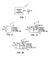
- FIG. 1 shows an article surveillance system utilizing a tag in accordance with the principles of the present invention
- FIGS. 2 and 3 illustrate first and second embodiments of the tag of FIG. 1;
- FIG. 4 shows a further article surveillance system using a tag in accordance with the principles of the present invention.
- FIG. 1 shows a magnetic article surveillance system 1 utilizing a tag 11 in accordance with the principles of the present invention.
- the system 1 is adapted to detect the presence of articles, such as, for example, the article 12. This is accomplished by affixing the tag 11 to the article 12 and detecting the presence of the tag.
- the system 1 comprises a transmitter 2 which propagates or transmits a magnetic field in the region of the article 12.
- the tag 11 is adapted to respond to the magnetic field by generating an acoustic signal.
- the tag 11 is further adapted so that the acoustic signal generated is audible. This permits the location of the tag and article to be more easily and quickly determined.
- FIG. 2 shows the details of the tag 11.
- the tag comprises an antenna 13, which may be fabricated from a number of turns of wire, and a piezoelectric element or crystal 14 whose resonant frequency is in the audible range.
- the antenna 13 and the crystal 14 are connected in parallel and act to respond to signals at the acoustic resonant frequency of the crystal. This is accomplished by forming the antenna 13 so that its equivalent inductance L and the equivalent capacitance C of the piezoelectric crystal 14 enable the desired response.
- the transmitter 2 transmits a magnetic field of suitable magnitude at or near the resonant frequency of the crystal 14, this field induces a voltage in the circuit formed by the crystal and antenna 13 of the tag 11.
- the induced voltage then excites the crystal 14 causing it to mechanically vibrate at its resonant frequency. This, in turn, produces the aforementioned audible acoustic signal, which allows the location of the tag 11 to be determined by following the sound.
- FIG. 3 shows a second embodiment of the tag 11.
- This embodiment permits the transmitter 2 to operate at frequencies other than the resonant frequency of piezoelectric crystal 14.
- the transmitter 2 transmits a higher frequency signal which is amplitude modulated at the resonant frequency of the crystal.
- the tag 11 of FIG. 3 is provided with an AM demodulator which demodulates the signal to recover the resonant frequency signal.
- the AM demodulator comprises a rectifier, shown as Schotky diode 15, placed in series with the antenna 13 and crystal 14, and a resistor 16 placed in parallel with the crystal.
- the demodulator makes the circuit of the antenna and crystal responsive to the resonant frequency signal, causing the crystal to mechanically vibrate and deliver the desired audible signal.
- the electrical circuit formed by the crystal 14 and the antenna 13 need not itself be resonant at the acoustic resonant frequency of the crystal. All that is required is that the circuit be sufficiently responsive at such acoustic resonant frequency to provide a signal to the crystal 14 of high enough level to cause the crystal to mechanically vibrate. Accordingly, in the case of the FIG. 3 embodiment, the resonant frequency of the circuit may be selected to be at the frequency of transmission of the magnetic field so as to promote efficient reception of the signal, as long as the circuit is also sufficiently responsive to the demodulated signal to provide an audible signal from the crystal.
- the piezoelectric crystal 14 was a 7BB-27-4 piezoelectric sounder manufactured by Murata Erie.
- the crystal had a resonant frequency of approximately 3.3 kHz and an equivalent capacitance of 17nf.
- the antenna 13 comprised 173 turns of 39 gauge MAG wire and had an equivalent inductance of 3.3 mH.
- the same tag 11 was formed in accordance with the Fig. 3 embodiment by using an HP 2800311 Schotky diode as rectifier element 15 and a 10K resistor as resistor 16.
- the nature of the transmitter 2 will depend upon a variety of factors, an important one of which is the level of the magnetic field needed to cause a discernible audible output from the tag 11.
- the transmitter 2 may be a unit which is situated in or can be brought into close proximity to the article 12.
- the transmitter 2 may be included in a hand held unit which scans the articles.
- FIG. 4 illustrates an electronic article surveillance system 41 in which the transmitter 2 is such a hand held unit, and in which, prior to use of the transmitter 2, a further transmitter 42 is used to first detect the presenece of the tag 11 and article 12 in an interrogation zone 43. More particularly, in the FIG. 4 embodiment, the tag 11 causes perturbations to the magnetic field transmitted from the transmitter 42. These perturbations are electrically detected by an antenna and receiver 44 and the detected perturbations used to sound an alarm 45 to indicate presence of the tag 11 in the zone 43.
- the transmitter 2 in the hand held unit is brought close to the article 12 in the zone 43 and the transmitter 2 is then caused to transmit its magnetic field.
- the tag 11 responds to this field by generating an audible acoustic signal, as above-described, thereby identifying the location of the article 12.
- the field transmitted by the transmitter 42 is preferably at frequency which promotes efficient coupling of energy into the tag 11. More preferably, it is at the resonant frequency of the circuit of the antenna 13 and piezoelectric crystal 14 making up the tag 11.
- the field transmitted by the transmitter 2 is preferably at a frequency to ensure an audible tag output. More preferably, it is at the acoustic resonant frequency of the crystal 14 of the tag 11.
- the system of FIG. 4 may be realized without use of a separate hand held unit for the transmitter 2.
- the field of the transmitter 42 can serve to cause both an alarm output from the alarm 45 and an audible output from the tag 11 when the tag 11 is present in the zone 43. This can be accomplished by the transmitter 42 transmitting a field which is at the resonant frequency of the circuit of the antenna 13 and crystal 14 and which is also amplitude modulated at the acoustic resonant frequency of the crystal. With this type of field, the circuit of the tag will cause a sufficient perturbation of the transmitted field to alarm the unit 45, while at the same time recovering sufficient modulated signal to cause audible vibration of the crystal 14 in the manner described above.
- Another possible modification of the system of FIG. 4, is to also use a single transmitter 42 and to replace the antenna and receiver 44 with an acoustic receiver.
- the tag of FIG. 2 would be used.
- the transmitted field would be at the acoustic resonant frequency of the crystal 14 and of such magnitude that the resultant acoustic signal from the crystal would be audible and at a high enough level to be picked up by the receiver 44, causing the alarm 45 to also sound.
- the tag 11 of the invention was adapted to provide to transmitted electromagnetic field that was amplitude modulated at the acoustic resonant frequency of the crystal 14.
- the tag 11 may instead be designed to be responsive to transmitted electromagnetic waves which are frequency modulated at the latter acoustic resonant frequency.
- the tag 11 of FIG. 3 would be further modified to include capacitor C1 (shown in dotted line in FIG. 3) which together with the antenna inductance L forms a resonant circuit at the acoustic resonant frequency.
- the tag 11 will act to frequency demodulate the transmitted signal to recover the acoustic resonant frequency signal. The recovered signal will, in turn, then cause the crystal to resonate and provide the audible response.
Landscapes
- Physics & Mathematics (AREA)
- Engineering & Computer Science (AREA)
- Automation & Control Theory (AREA)
- Computer Security & Cryptography (AREA)
- Electromagnetism (AREA)
- General Physics & Mathematics (AREA)
- Acoustics & Sound (AREA)
- Burglar Alarm Systems (AREA)
- Geophysics And Detection Of Objects (AREA)
- Piezo-Electric Transducers For Audible Bands (AREA)
Applications Claiming Priority (2)
| Application Number | Priority Date | Filing Date | Title |
|---|---|---|---|
| US44632289A | 1989-12-05 | 1989-12-05 | |
| US446322 | 1995-05-22 |
Publications (2)
| Publication Number | Publication Date |
|---|---|
| EP0431343A2 true EP0431343A2 (fr) | 1991-06-12 |
| EP0431343A3 EP0431343A3 (en) | 1992-04-08 |
Family
ID=23772155
Family Applications (1)
| Application Number | Title | Priority Date | Filing Date |
|---|---|---|---|
| EP19900121452 Withdrawn EP0431343A3 (en) | 1989-12-05 | 1990-11-09 | Audible tag for magnetic electronic article surveillance systems |
Country Status (5)
| Country | Link |
|---|---|
| EP (1) | EP0431343A3 (fr) |
| JP (1) | JPH03244099A (fr) |
| AR (1) | AR247308A1 (fr) |
| BR (1) | BR9005420A (fr) |
| CA (1) | CA2020952A1 (fr) |
Cited By (1)
| Publication number | Priority date | Publication date | Assignee | Title |
|---|---|---|---|---|
| WO2014043177A1 (fr) * | 2012-09-12 | 2014-03-20 | Strata Proximity Systems, Llc | Dispositif intégré d'alarme |
Families Citing this family (2)
| Publication number | Priority date | Publication date | Assignee | Title |
|---|---|---|---|---|
| CN108564754B (zh) * | 2018-06-15 | 2024-06-04 | 宁波讯强电子科技有限公司 | 一种声磁防盗标签及其偏置片 |
| JP7163273B2 (ja) * | 2019-12-26 | 2022-10-31 | 第一三共エスファ株式会社 | 薬剤包装体及び薬剤所在確認システム |
Family Cites Families (1)
| Publication number | Priority date | Publication date | Assignee | Title |
|---|---|---|---|---|
| GB1292380A (en) * | 1969-04-02 | 1972-10-11 | Unisearch Ltd | Electronic surveillance systems |
-
1990
- 1990-07-11 CA CA 2020952 patent/CA2020952A1/fr not_active Abandoned
- 1990-08-16 AR AR31761590A patent/AR247308A1/es active
- 1990-10-26 BR BR909005420A patent/BR9005420A/pt active Search and Examination
- 1990-11-09 EP EP19900121452 patent/EP0431343A3/en not_active Withdrawn
- 1990-11-29 JP JP2326187A patent/JPH03244099A/ja active Pending
Cited By (2)
| Publication number | Priority date | Publication date | Assignee | Title |
|---|---|---|---|---|
| WO2014043177A1 (fr) * | 2012-09-12 | 2014-03-20 | Strata Proximity Systems, Llc | Dispositif intégré d'alarme |
| US9280885B2 (en) | 2012-09-12 | 2016-03-08 | Strata Safety Products, Llc | Integrated alarm device |
Also Published As
| Publication number | Publication date |
|---|---|
| BR9005420A (pt) | 1991-09-17 |
| AR247308A1 (es) | 1994-11-30 |
| JPH03244099A (ja) | 1991-10-30 |
| EP0431343A3 (en) | 1992-04-08 |
| CA2020952A1 (fr) | 1991-06-06 |
Similar Documents
| Publication | Publication Date | Title |
|---|---|---|
| AU704042B2 (en) | Multi-bit EAS marker powered by interrogation signal in the eight Mhz band | |
| US5012224A (en) | Audible tag for magnetic electronic article surveillance systems | |
| CA2119774C (fr) | Systeme d'identification automatique radiofrequence | |
| EP0377257A1 (fr) | Système d'identification | |
| WO2010108022A1 (fr) | Dispositif de protection rfid et procédés associés | |
| WO2001086967A3 (fr) | Systeme de detection et d'identification par frequence radioelectrique | |
| US10019663B1 (en) | RFID disruption device and related methods | |
| ES2002150A6 (es) | Transpondedor portatil, etiqueta codificada que lo incluye y sistema detector de presencia, especialmente para vigilar articulos en tiendas. | |
| WO1990012474A1 (fr) | Systeme d'identification de pneus de vehicules | |
| EP0369622A2 (fr) | Lecture rapprochée d'une étiquette codée | |
| ATE265726T1 (de) | Sicherheitssystem zur durchgangsüberwachung von artikeln | |
| EP0431343A2 (fr) | Etiquette audible pour systèmes magnétiques et électroniques pour la surveillance d'articles | |
| US5010320A (en) | Self modulating electronic article surveillance marker | |
| CA2075991C (fr) | Systeme de securite pour surveiller le passage de produits dans des zones definies | |
| EP1793355A3 (fr) | Système de surveillance d'article électronique magnétomécanique et procédé utilisant la détection de bande latérale | |
| JP2000339422A (ja) | Idタグ | |
| JPS5857796B2 (ja) | アクテイブソシニヨル ハンベツソウチ | |
| EP2465103A1 (fr) | Procédé et dispositif à des fins d' identification | |
| CN1003747B (zh) | 按“号码”配对的射频物品防失报警系统 | |
| JPH0810357A (ja) | ゴルフボール探知システム | |
| JP2001356156A (ja) | 電磁波方式レーンマーカ統合検出装置 | |
| KR20030021656A (ko) | 물품분실 방지경보 및 물품 관리장치 | |
| Lawrence | Radio tags and microchip tagging | |
| JPS62226078A (ja) | 移動体識別方法 |
Legal Events
| Date | Code | Title | Description |
|---|---|---|---|
| PUAI | Public reference made under article 153(3) epc to a published international application that has entered the european phase |
Free format text: ORIGINAL CODE: 0009012 |
|
| AK | Designated contracting states |
Kind code of ref document: A2 Designated state(s): DE FR GB SE |
|
| PUAL | Search report despatched |
Free format text: ORIGINAL CODE: 0009013 |
|
| AK | Designated contracting states |
Kind code of ref document: A3 Designated state(s): DE FR GB SE |
|
| STAA | Information on the status of an ep patent application or granted ep patent |
Free format text: STATUS: THE APPLICATION IS DEEMED TO BE WITHDRAWN |
|
| 18D | Application deemed to be withdrawn |
Effective date: 19921009 |