EP0431401A1 - Rohrschelle - Google Patents
Rohrschelle Download PDFInfo
- Publication number
- EP0431401A1 EP0431401A1 EP90122261A EP90122261A EP0431401A1 EP 0431401 A1 EP0431401 A1 EP 0431401A1 EP 90122261 A EP90122261 A EP 90122261A EP 90122261 A EP90122261 A EP 90122261A EP 0431401 A1 EP0431401 A1 EP 0431401A1
- Authority
- EP
- European Patent Office
- Prior art keywords
- pipe clamp
- pipe
- clamp according
- cylinders
- pipe ends
- Prior art date
- Legal status (The legal status is an assumption and is not a legal conclusion. Google has not performed a legal analysis and makes no representation as to the accuracy of the status listed.)
- Granted
Links
- 238000007789 sealing Methods 0.000 claims abstract description 30
- 230000005489 elastic deformation Effects 0.000 claims 1
- 241001484259 Lacuna Species 0.000 abstract 1
- 235000002566 Capsicum Nutrition 0.000 description 2
- 241000758706 Piperaceae Species 0.000 description 2
- 235000013312 flour Nutrition 0.000 description 2
- 238000010276 construction Methods 0.000 description 1
- 238000006073 displacement reaction Methods 0.000 description 1
- 235000013599 spices Nutrition 0.000 description 1
Images
Classifications
-
- F—MECHANICAL ENGINEERING; LIGHTING; HEATING; WEAPONS; BLASTING
- F16—ENGINEERING ELEMENTS AND UNITS; GENERAL MEASURES FOR PRODUCING AND MAINTAINING EFFECTIVE FUNCTIONING OF MACHINES OR INSTALLATIONS; THERMAL INSULATION IN GENERAL
- F16L—PIPES; JOINTS OR FITTINGS FOR PIPES; SUPPORTS FOR PIPES, CABLES OR PROTECTIVE TUBING; MEANS FOR THERMAL INSULATION IN GENERAL
- F16L21/00—Joints with sleeve or socket
- F16L21/06—Joints with sleeve or socket with a divided sleeve or ring clamping around the pipe ends
- F16L21/065—Joints with sleeve or socket with a divided sleeve or ring clamping around the pipe ends tightened by tangentially-arranged threaded pins
-
- F—MECHANICAL ENGINEERING; LIGHTING; HEATING; WEAPONS; BLASTING
- F16—ENGINEERING ELEMENTS AND UNITS; GENERAL MEASURES FOR PRODUCING AND MAINTAINING EFFECTIVE FUNCTIONING OF MACHINES OR INSTALLATIONS; THERMAL INSULATION IN GENERAL
- F16L—PIPES; JOINTS OR FITTINGS FOR PIPES; SUPPORTS FOR PIPES, CABLES OR PROTECTIVE TUBING; MEANS FOR THERMAL INSULATION IN GENERAL
- F16L21/00—Joints with sleeve or socket
- F16L21/002—Sleeves or nipples for pipes of the same diameter; Reduction pieces
- F16L21/005—Sleeves or nipples for pipes of the same diameter; Reduction pieces made of elastic material, e.g. partly or completely surrounded by clamping devices
Definitions
- the invention relates to a pipe clamp according to the preamble of claim 1.
- Such a pipe clamp has become known, for example, from DE-A-1 750 138.
- the tensioning device is actuated, which here consists of an elastically screwable ring. Sliding the rings on means that the pipes cannot be pre-assembled butt-to-butt, and that there is inevitably a gap between their two butting surfaces. This is irrelevant if the same medium is always passed through the pipes, but is unpleasant if different media have to be conveyed through one after the other.
- the invention is based on the object of designing a pipe connection clamp of the type mentioned above in such a way that the two abutting surfaces of the pipes to be connected to one another are avoided with certainty. According to the invention, this object is achieved by the characterizing features of claim 1.
- the sealing ring can also evade in the circumferential direction if it is subject to the pressure of the tensioning device.
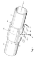
- FIG. 1 shows two pipe ends R1 and R2 joined to one another at a joint S, the connection area of the pipe ends being enclosed by a pipe clamp RS according to the invention.
- This pipe clamp RS can, due to the design described below, also be retrofitted after the pipes R1, R2 (eg by other clamps of a conventional type, not shown here, removed from the clamp RS, or by other fastening means) Fig. 1 apparent position have been brought.
- the pipe clamp RS has two half cylinders H1 and H2, which have fastening flanges 13 along their two longitudinal section lines, which are clamped against one another by means of bolts 12 in such a way that the two half cylinders H1 and H2 clamp the pipe ends R1 and R2 in a force-locking manner and thereby the ones shown in FIG 3 clamp the sealing and train protection devices shown between the half cylinders H1, H2 and the pipe ends R1, R2.
- this design is not absolutely necessary, since it would also be possible to keep the two half cylinders H1, H2 constantly pivotally connected by means of a hinge instead of one of the flanges 13 and to provide a fastening flange 13 only on the opposite side.
- One of the two half cylinders, H2 has a fastening flange 18 lying transversely to the pipe axis A, with the aid of which the entire pipe clamp can be fastened to a fastening plate BP by means of one or more screw bolts SB, which can be screwed into screw holes 1.
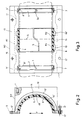
- Fig. 2 which shows a radial section through the half cylinder H2
- a semicircle cut cylinder body 14 of the pipe clamp as well as the axially extending fastening flanges 13 and the fastening flange 18 running transversely to the pipe axis, which has screw holes 1 for fastening the pipe clamp to a fastening plate BP, as shown in FIG. 1.
- a hole 12 'for receiving a screw bolt 12 by means of which the half cylinder H2 shown can be screwed to the symmetrical half cylinder H1 (see FIG. 1).
- the bolt 12 can optionally be screwed with a nut (not shown), or one of the two half-cylinders H1 or H2 has an internal thread within the hole 12 '.
- FIG. 3 shows a section through the pipe clamp according to the invention along the division plane T (see FIG. 2), in which the arrangement of the strain relief rings 2, 4 and the sealing device 6 on the inside of the half cylinder H2 can be seen.
- the essentially cylindrical inner surface of the half cylinder H2 has a recess 9 in its central region, the depth of which in certain regions is less than the radial thickness of the sealing device 6.
- This recess 9 has a central region 11, the diameter of which is smaller than the diameter of two ring grooves 10 and 10 'adjacent to the central region 11, so that when the pipe clamp is tensioned, a force acting radially on the sealing device 6 and further on the pipe ends R1 and R2 essentially acts on the loading range of the central region 11 is limited, whereas the recesses 10 and 10 ', which can accommodate material displacements occurring in the region of the central region 11 due to the pinching of the sealing device 6. In particular, this also prevents the pipe joint S from being widened when screwed together by the gasket that is constrained.
- two annular grooves 14 'and 14 are provided, which serve to partially accommodate the strain relief rings 2 and 4.
- These strain relief rings essentially have a triangular profile, the cylindrical outer surface 7 of the strain relief rings being at the bottom of the ring grooves 14 'and 14 "come to rest, whereas the cutting edges 8 and 8' protrude from the ring grooves 14 'and 14" even when the strain relief rings are in the maximum recessed position.
- the outer surfaces 15 'of the half cylinders H1 and H2 can either be formed by straight cylinder surfaces, or depressions 16 and 17 can be formed to save material and to reduce weight.
- the annular elements which are formed by the strain relief rings 2 and 4, as well as by the sealing device 6, can be provided with slots in order to facilitate a reduction in their circumference or diameter when the two half-shells H1 and H2 are clamped together.
- Such slots can either be parallel to the axis or, advantageously, according to one of the shapes shown.
- the strain relief ring 2 with a slot 3 that extends obliquely to the axis
- the strain relief ring 4 with a type of Tongue and groove connection shaped slot 3a
- the sealing device 6 equipped with a step-shaped slot 5, the latter in the area of the butt plane S between the two pipe ends R1 and R2, an area running obliquely to the pipe axis and in the edge areas adjacent to this area axially parallel dividing slots having.
- the sealing device 6 it is possible, which is particularly advantageous in the case of the sealing device 6, to provide the dividing slot approximately tangentially, so that the opposite ends of the sealing device overlap like a wedge, as is the case, for example, with the wedge cut of a motion picture film.
- an approximately tangential division slot could also be stepped, as is shown by the slot 19 in FIG. 2.
- a slot area is obtained which is larger than would correspond to an axially parallel dividing slot.
- all the ring-shaped elements can also have two or more slots, although all slots are expediently arranged outside the division plane T in order to ensure an optimal seal.
- the central region 11 of the half-cylinders H1 and H2 can also be formed by a spring ring encompassing the sealing device 6, or, in the event that the sealing ring consists of relatively hard material, the central region 11 with an elastic covering or at least be provided with individual cushions.
- the sealing cylinder 6 in any case has a radial thickness which is greater than the difference in the diameter of the central region 11 and the pipe ends R1 and R2. This ensures that when the inner surfaces of the half-cylinders H1 and H2 and the outer surfaces R1 and R2 lie tightly against one another, the sealing device 6 at least in the region of the central part Reichs 11 of the half cylinder, which is to be arranged during assembly in the area of the butt surface S, is pressurized.
- the radial depth of the ring grooves 14 'and 14 "or the radial dimension of the profile of the strain relief rings 2 and 4 can be selected so that the outstanding height of the cutting edge 8 is pressed into the outer sides of the pipe ends to the extent that the tensioning device is tensioned with the usual effort the outer sides of the tube ends come to lie essentially snugly on the inner surfaces of the half cylinders H1 and H2.
- strain relief rings 2, 4 may be unnecessary for some applications.
- a mere clamp fit within the half cylinders H1, H2 can also be provided.
Landscapes
- Engineering & Computer Science (AREA)
- General Engineering & Computer Science (AREA)
- Mechanical Engineering (AREA)
- Clamps And Clips (AREA)
- Flanged Joints, Insulating Joints, And Other Joints (AREA)
- Mutual Connection Of Rods And Tubes (AREA)
- Supports For Pipes And Cables (AREA)
- Joints With Pressure Members (AREA)
- Quick-Acting Or Multi-Walled Pipe Joints (AREA)
- Discharge Heating (AREA)
Abstract
Description
- Die Erfindung bezieht sich auf eine Rohrschelle nach dem Oberbegriffe des Anspruches 1.
- Eine derartige Rohrschelle ist beispielsweise aus der DE-A-1 750 138 bekannt geworden. Dabei werden nach dem Überziehen des zylindrischen Dichtungsringes über die Rohrenden bzw. dem Aufsetzen von Zugsicherungsringen auf die Rohrenden die Spanneinrichtung betätigt, die hier aus einem elastisch zusammenschraubbaren Ring besteht. Das Aufschieben der Ringe bedingt, dass die Rohre nicht Stoss an Stoss vormontiert sein können, ja dass zwangsläufig zwischen ihren beiden Stossflächen ein Spalt verbleibt. Dies spielt dann keine Rolle, wenn durch die Rohre stets ein und dasselbe Medium geführt wird, ist aber unangenehm, wenn nacheinander verschiedene Medien hindurchbefördert werden müssen. So ist es verständlich, dass es im Falle pneumatischer Förderleitungen vielleicht einmal erwünscht ist, Gewürzpaprika hindurchzuleiten, das nächste Mal aber etwa Mehl, wobei niemand die Reste des vorher transportierten Paprika in Form roter Spuren im Mehl entdecken möchte. Zwar lassen sich Rohre durch alle möglichen bekannten Einrichtungen im allgemeinen gut reinigen, nicht jedoch, wenn dazwischen Dichtungsspalte klaffen.
- Hinzu tritt noch ein weiterer Effekt, der den oben geschilderten Nachteil noch verstärkt. Wird nämlich der Dichtungsring durch die Spanneinrichtung gegen die Rohrwände gepresst, so weicht er elastisch nach den Seiten, d.h. in Axialrichtung, aus. Dabei nimmt er auch die Rohre mit, die dann, selbst wenn sie vorher Stoss an Stoss lagen, nun eine Dichtungsfuge erhalten. Obwohl Zugentlastungsringe dieser Erscheinung ziemlich gut entgegenwirken können, vermögen sie ihn nicht völlig zu verhindern.
- Der Erfindung liegt die Aufgabe zugrunde, eine Rohrverbindungsschelle der oben genannten Art so auszubilden, dass ein Auseinanderklaffen der beiden Stossflächen der miteinander zu verbindenden Rohre mit Sicherheit vermieden wird. Erfindungsgemäss wird diese Aufgabe durch die kennzeichnenden Merkmale des Anspruches 1 gelöst.
- Dadurch, dass die Dichtung Raum erhält, um sich beim Spannen zu verformen, überträgt sie keine axialen Kräfte mehr auf die Rohre, und diese können Stossfläche an Stossfläche aneinandergelegt bleiben.
- Zweckmässig sind die Merkmale des Anspruches 3 als zusätzliche Sicherung vorgesehen, da auf diese Weise auch anderen, als von der Dichtung ausgehenden, Axialkräften begegnet werden kann.
- Durch die Ausbildung mit geteilten Ringen gemäss Anspruch 4 ist es möglich, dieselben auch nach der Montage der Rohre anzubringen, so dass die Rohre bereits Stoss an Stoss vormontiert werden können. Ausserdem kann dadurch der Dichtungsring gegebenenfalls auch in Umfangsrichtung ausweichen, wenn er dem Drucke der Spanneinrichtung unterliegt.
- Durch die Ausführung der Rohrschelle in Form von radial aufeinander zu spannbaren Halbzylindern gemäss Anspruch 7 wird ein gleichmässigerer Druck auf den Dichtungsring ausgeübt, als es bei dar gattungsbildenden Konstruktion der Fall war.
- Die Erfindung wird nunmehr anhand der Zeichnung beispielsweise erläutert, wobei die
- Fig. 1
- eine über zwei zu verbindende Rohrenden montierte Rohrschelle entsprechend der vorliegenden Erfindung in fertig montierter Weise,
- Fig. 2
- einen Radialschnitt durch einen Halbzylinder der er findungsgemässen Rohrschelle, und
- Fig. 3
- einen Axialschnitt durch dieselbe erfindungsgemässe Rohrschelle darstellt.
- In Fig. 1 sind zwei an einem Stoss S aneinandergefügte Rohrenden R1 und R2 dargestellt, wobei der Verbindungsbereich der Rohrenden mittels einer erfindungsgemässen Rohrschelle RS umschlossen ist. Diese Rohrschelle RS kann, auf Grund ihrer in der Folge beschriebenen Ausbildung, auch nachträglich angebracht werden, nachdem die Rohre R1, R2 (z.B. durch andere, von der Schelle RS entfernte, hier nicht gezeigte Schellen herkömmlicher Art oder durch andere Befestigungsmittel) in die aus Fig. 1 ersichtliche Lage gebracht worden sind.
- Die Rohrschelle RS weist zwei Halbzylinder H1 und H2 auf, welche entlang ihrer beiden Längsschnittlinien Befestigungsflansche 13 besitzen, welche mittels Bolzen 12 derart gegeneinander verspannt sind, dass die beiden Halbzylinder H1 und H2 die Rohrenden R1 und R2 in kraftschlüssiger Weise umspannen und hierbei die in Fig. 3 dargestellten Dichtungs- und Zugsicherungseinrichtungen zwischen den Halbzylindern H1, H2, und den Rohrenden R1, R2, einklemmen. Diese Ausbildung ist aber nicht zwingend erforderlich, da es ebenso möglich wäre, die beiden Halbzylinder H1, H2 mittels eines Scharniers, an Stelle eines der Flanschen 13 ständig schwenkbar verbunden zu halten und nur an der gegenüberliegenden Seite einen Befestigungsflansch 13 vorzusehen.
- Einer der beiden Halbzylinder, H2, weist einen quer zur Rohrachse A liegenden Befestigungsflansch 18 auf, mit Hilfe dessen die gesamte Rohrschelle an einer Befestigungsplatte BP mittels eines oder mehrerer Schraubbolzen SB, welche in Schraublöcher 1 ein-schraubbar sind, befestigt werden kann.
- In Fig. 2, welche einen Radialschnitt durch den Halbzylinder H2 zeigt, erkennt man den durch die Teilungsebene T in einen Halb-kreis zerschnittenen Zylinderkörper 14 der Rohrschelle, sowie die axial verlaufenden Befestigungsflansche 13 und den quer zur Rohrachse verlaufenden Befestigungsflansch 18, welcher Schraublöcher 1 zur Befestigung der Rohrschelle an einer Befestigungsplatte BP, wie unter Fig. 1 dargestellt, aufweist.
- Auf der Innenseite des halbzylindrischen Körpers 14 erkennt man die zylinderförmige Dichtungseinrichtung 6, sowie die nach innen hervorstehende Schneidkante 8 der ringförmigen Elemente der Zugentlastungseinrichtung, welche im folgenden auch Zugentlastungsringe genannt werden.
- Ferner erkennt man in einem der Befestigungsflansche 13 ein Loch 12' zur Aufnahme eines Schraubbolzens 12, mit Hilfe dessen der dargestellte Halbzylinder H2 mit dem symmetrischen Halbzylinder H1 (s. Fig. 1) verschraubbar ist. Zum Zusammenspannen der beiden Halbschalen H1, H2 kann der Bolzen 12 wahlweise mit einer (nicht dargestellten) Mutter verschraubt werden, oder einer der beiden Halbzylinder H1 oder H2 besitzt ein Innengewinde innerhalb des Loches 12'.
- Die Fig. 3 zeigt einen Schnitt durch die erfindungsgemässe Rohr-schelle entlang der Teilungsebene T (s. Fig. 2), worin die Anordnung der Zugentlastungsringe 2, 4 sowie der Dichtungseinrichtung 6 auf der Innenseite des Halbzylinders H2 ersichtlich ist.
- Die im wesentlichen zylindrische Innenfläche des Halbzylinders H2 weist in ihrem Mittelbereich eine Ausnehmung 9 auf, deren Tiefe in bestimmten Bereichen geringer ist, als die radiale Dicke der Dichtungseinrichtung 6. Diese Ausnehmung 9 besitzt einen Mittelbereich 11, deren Durchmesser geringer ist, als der Durchmesser von zwei dem Mittelbereich 11 benachbarten Ringnuten 10 und 10', so dass beim Spannen der Rohrschelle eine radial auf die Dichtunseinrichtuing 6 und im weiteren auf die Rohrenden R1 und R2 wirkende Kraft im wesentlichen auf den Be reich des Mittelbereichs 11 beschränkt ist, wohingegen die Ausnehmungen 10 und 10', die durch die Quetschung der Dichtungseinrichtung 6 im Bereich des Mittelbereichs 11 auftretenden Materialverschiebungen aufnehmen können. Dies verhindert insbesondere auch, dass sich der Rohrstoss S beim Verschrauben durch die sich einzwängende Dichtung verbreitert werden könnte.
- In den axialen Randbereichen des Halbzylinders H2 sind zwei Ringnuten 14' und 14" vorgesehen, welche der teilweisen Aufnahme der Zugentlastungsringe 2 und 4 dienen. Diese Zugentlastungsringe weisen im wesentlichen ein dreieckförmiges Profil auf, wobei die zylindrische Aussenfläche 7 der Zugentlastungsringe auf den Grund der Ringnuten 14' und 14" zu liegen kommt, wohingegen die Schneidkanten 8 und 8' selbst bei maximal versenkter Stellung der Zugentlastungsringe aus den Ringnuten 14' und 14" hervorstehen.
- Hierdurch wird gewährleistet, dass beim Zusammenspannen der beiden Halbzylinder H1 und H2 die Schneidkanten 8 und 8' in die zylindrischen Aussenflächen der Rohrenden R1 und R2 eingepresst werden.
- Die Aussenflächen 15' der Halbzylinder H1 und H2 können entweder durch gerade Zylinderflächen gebildet werden, oder es können Einsenkungen 16 und 17 zur Materialeinsparung und Gewichtserleichterung gebildet werden.
- Die ringförmigen Elemente, welche von den Zugentlastungsringen 2 und 4, sowie von der Dichtungseinrichtung 6 gebildet werden, können mit Schlitzen versehen sein, um eine Verminderung ihres Umfangs bzw. Durchmessers beim Zusammenspannen der beiden Halb-schalen H1 und H2 zu erleichtern. Derartige Schlitze können entweder achs-parallel oder, vorteilhafterweise, entsprechend einer der dargestellten Formen ausgebildet sein. Beispielsweise ist der Zugentlastungsring 2 mit einem schräg zur Achse verlaufenden Schlitz 3, der Zugentlastungsring 4 mit einem nach Art einer Feder- und Nutverbindung geformten Schlitz 3a, und die Dichtungseinrichtung 6 mit einem stufenförmigen Schlitz 5 ausgestattet, welcher letztere im Bereich der Stossebene S zwischen beiden Rohrenden R1 und R2 einen schräg zur Rohrachse verlaufenden Bereich und in den zu diesem Bereich benachbarten Randbereichen achs-parallele Teilungsschlitze aufweist.
- Ferner besteht die Möglichkeit, welche besonders im Falle der Dichtungseinrichtung 6 von Vorteil ist, den Teilungsschlitz etwa tangential anzubringen, so dass die sich gegenüberliegenden Enden der Dichtungseinrichtung sich keilartig überlappen, wie dies beispielsweise beim Keilschnitt eines Kinofilms der Fall ist. Prinzipiell könnte ein solcher, annähernd tangentialer Teilungsschlitz auch gestuft verlaufen, wie dies an Hand des Schlitzes 19 in Fig. 2 dargestellt ist. In jedem der beschriebenen Fälle erhält man eine Schlitzfläche, die grösser ist, als einem achsparallelen Teilungsschlitz entspräche.
- Vorteilhafterweise können alle ringförmigen Elemente auch zwei oder mehrere Schlitze aufweisen, wobei jedoch zweckmässig alle Schlitze ausserhalb der Teilungsebene T angeordnet werden, um eine optimale Dichtung zu gewährleisten.
- Entsprechend einer Ausführungsart der Erfindung kann der Mittelbereich 11 der Halbzylinder H1 und H2 auch durch einen, die Dichtungseinrichtung 6 umspannenden Federring gebildet sein, oder es kann, im Falle dass der Dichtungsring aus relativ hartem Material besteht, der Mittelbereich 11 mit einem elastischen Belag oder zumindest mit einzelnen Polstern versehen sein. Der Dichtungszylinder 6 weist jedoch in jedem Fall eine radiale Dicke auf, welche grösser ist als der Unterschied der Durchmesser des Mittelbereichs 11 und der Rohrenden R1 und R2. Hierdurch wird gewährleistet, dass beim satten Aneinanderliegen der Innenflächen der Halbzylinder H1 und H2 und der Aussenflächen R1 und R2 die Dichtungseinrichtung 6 zumindest im Bereich des Mittelbe reichs 11 der Halbzylinder, welcher bei der Montage im Bereich der Stossfläche S anzuordnen ist, unter Druck gesetzt wird.
- Vorteilhafterweise kann die radiale Tiefe der Ringnuten 14' und 14" oder die Radialdimension des Profils der Zugentlastungsringe 2 und 4 so gewählt werden, dass die herausragende Höhe der Schneidkante 8 beim Spannen der Spanneinrichtung unter üblichem Kraftaufwand in die Aussenseiten der Rohrenden soweit hineingepresst werden, dass die Aussenseiten der Rohrenden im wesentlichen satt auf die Innenflächen der Halbzylinder H1 und H2 zu liegen kommen.
- Die Erfindung wurde anhand eines Ausführungsbeispiels im Detail beschrieben, ohne jedoch auf die konstruktiven Einzelheiten dieses Ausführungsbeispiels beschränkt zu sein. Beispielsweise mögen die Zugentlastungsringe 2, 4 für manche Anwendungen entbehrlich sein. Beispielsweise zur Zugentlastung auch ein blosser Klemmsitz innerhalb der Halbzylinder H1, H2 vorgesehen sein.
Claims (9)
- Rohrschelle zum Verbinden zweier Rohrenden (R1, R2), von denen jedes eine Stossfläche aufweist, die mit der Stossfläche des anderen Rohrendes im wesentlichen glatt zusammenfügbar ist, mit einem die Stossfläche beider Rohrenden umfangsmässig umschliessenden, radial flach gegen die Rohrenden spannbaren zylindrischen Dichtungsring (6) und vorzugsweise einer, radial von aussen gegen die Rohrenden spannbaren und diese gegen axiales Auseinanderziehen sichernden Zugssicherungseinrichtung (2, 4), wobei der Dichtungsring (6), gegebenenfalls auch gemeinsam mit der Zugssicherungseinrichtung (2, 4), mittels einer einen radialen Druck ausübenden Spanneinrichtung (H1, H2) gegen die Aussenwände der Rohrenden (R1, R2) spannbar ist, dadurch gekennzeichnet, dass die Spanneinrichtung (H1, H2) neben einer Klemmfläche (11), mit deren Hilfe beim Spannen der Spanneinrichtung ein gleichmässig über den Umfang der Dichtungseinrichtung (6) verteilter, diese in radialer Richtung gegen die Stelle der aneinanderstossenden Stossflächen (S) zusammengepressender Druck erzeugbar ist, wenigstens einen Ring (10, 10') verminderten Durchmessers zur Aufnahme der elastischen Verformung beim Spannen des Dichtungsringes (6) aufweist.
- Rohrschelle nach Anspruch 1, dadurch gekennzeichnet, dass im axialen Mittelbereich der Spanneinrichtung ein die Klemmfläche (11) bildender, nach innen hervorstehende Ring angeordnet ist, zu dessen beiden Seiten je eine Ringnut (10, 10') mit entsprechend verringertem Durchmesser angeordnet ist.
- Rohrschelle nach Anspruch 2, dadurch gekennzeichnet, dass jeder Ringnut (10, 10') eine jeweils im axialen Randbereich der Spanneinrichtung gelegene Ringnut (14, 14') zur teilweisen Aufnahme der ringförmiger Elemente (2, 4) der Zugsicherungseinrichtung zugeordnet ist.
- Rohrschelle nach Anspruch 1, 2 oder 3, dadurch gekennzeichnet, dass wenigstens die Dichtungseinrichtung (6), gegebenenfalls auch die Zugsicherungseinrichtung (2, 4), zumindest einen Teilungsschlitz (3, 3a, 5) besitzt, an dem er zum Herumlegen um das Rohr (R1, R2) zu öffnen ist.
- Rohrschelle nach Anspruch 4, dadurch gekennzeichnet, dass der Schlitz (3, 3a, 5) einen von der Axialrichtung abweicheden Verlauf aufweist, der zweckmässig einen schräg zur Achsrichtung (a) ausgerichteten Verlauf und/oder einen von einer Geraden abweichenden, z.B. einen gestuften (5) oder geschlängelten, Verlauf aufweist.
- Rohrschelle nach Anspruch 4 oder 5, dadurch gekennzeichnet, dass der Schlitz, gesehen im Querschnitt, etwa tangential ausgeführt ist, wobei der Ring (2, 4, 6) sich überlappende Bereiche aufweist.
- Rohrschelle nach einem der Ansprüche 1 bis 6, dadurch gekennzeichnet, dass die Spanneinrichtung zwei entlang einer Teilungsebene (T) zusammenspannbare, schalenartige Halbzylinder (H1, H2) besitzt, und dass vorzugsweise der Teilungschlitz (3, 3a, 5) des Dichtungsringes (6) ausserhalb der Teilungsebene (T) angeordnet ist bzw. jeder Halbzylinder (H1, H2) entlang seiner beiden Längsschnittlinien Flansche (13) aufweist, welche beim Zusammenfügen der beiden Halbzylinder zu einem, die beiden aufeinander ausgerichteten und aneinander anstossenden Rohrenden umschliessenden Vollzylinder paarweise in einander gegenüberliegende Positionen bringbar und mittels Spann- und Halteelementen (12, 12') gegeneinander spannbar und in gespannter Relativstellung fixierbar sind.
- Rohrschelle nach Anspruch 7, dadurch gekennzeichnet, dass zumindest einer der Halbzylinder (H1, H2) der Spanneinrichtung auf seiner Aussenfläche einen Befestigungsflansch (18) auf weist, mit Hilfe dessen die gesamte Rohrschelle an einer Haltefläche (BP) befestigbar ist.
- Rohrschelle nach Anspruch 8, dadurch gekennzeichnet, dass der Befestigungsflansch (18) zumindest zwei Schraublöcher (1) zur Aufnahme von mit der Haltefläche verbindbaren Bolzen (SB) aufweist.
Priority Applications (1)
| Application Number | Priority Date | Filing Date | Title |
|---|---|---|---|
| AT90122261T ATE82373T1 (de) | 1989-12-02 | 1990-11-22 | Rohrschelle. |
Applications Claiming Priority (2)
| Application Number | Priority Date | Filing Date | Title |
|---|---|---|---|
| DE3939979A DE3939979A1 (de) | 1989-12-02 | 1989-12-02 | Rohrschelle |
| DE3939979 | 1989-12-02 |
Publications (2)
| Publication Number | Publication Date |
|---|---|
| EP0431401A1 true EP0431401A1 (de) | 1991-06-12 |
| EP0431401B1 EP0431401B1 (de) | 1992-11-11 |
Family
ID=6394730
Family Applications (1)
| Application Number | Title | Priority Date | Filing Date |
|---|---|---|---|
| EP90122261A Expired - Lifetime EP0431401B1 (de) | 1989-12-02 | 1990-11-22 | Rohrschelle |
Country Status (6)
| Country | Link |
|---|---|
| EP (1) | EP0431401B1 (de) |
| AT (1) | ATE82373T1 (de) |
| DE (2) | DE3939979A1 (de) |
| DK (1) | DK0431401T3 (de) |
| ES (1) | ES2035694T3 (de) |
| GR (1) | GR3006351T3 (de) |
Families Citing this family (2)
| Publication number | Priority date | Publication date | Assignee | Title |
|---|---|---|---|---|
| DE10024951C2 (de) * | 2000-05-22 | 2002-04-18 | Coperion Waeschle Gmbh & Co Kg | Rohrhalterung für Förderleitungen, insbesondere in pneumatischen Langsamfördersystemen |
| DE20110994U1 (de) | 2001-07-03 | 2001-09-27 | Mick, Peter, 58708 Menden | Montagehilfe zum Montieren von Rohrleitungssträngen mit flexiblen Abschnitten |
Citations (4)
| Publication number | Priority date | Publication date | Assignee | Title |
|---|---|---|---|---|
| DE1750138A1 (de) * | 1967-05-10 | 1970-01-22 | Aeroquip Ag | Anschluss fuer glatte Rohrenden |
| US3790194A (en) * | 1972-08-02 | 1974-02-05 | Kelstan Plastic Prod Ltd | Pipe coupling |
| DE3626289C1 (en) * | 1986-08-02 | 1987-10-15 | Rasmussen Gmbh | Pipe coupling and process for producing a securing device for this pipe coupling |
| DE3737669C1 (de) * | 1987-11-06 | 1988-05-19 | Rasmussen Gmbh | Rohrkupplung |
Family Cites Families (9)
| Publication number | Priority date | Publication date | Assignee | Title |
|---|---|---|---|---|
| US2225208A (en) * | 1939-04-20 | 1940-12-17 | Merla Tod Company | Pipe coupling |
| US2227551A (en) * | 1939-06-07 | 1941-01-07 | Jolly L Morris | Pipe coupling and pipe clamp |
| US2776153A (en) * | 1948-01-26 | 1957-01-01 | Telford L Smith | Armored gasket for pipe repair clamp and the like |
| US2713352A (en) * | 1951-06-16 | 1955-07-19 | Edward H Schustack | Pipe coupling |
| DE2053949B2 (de) * | 1970-11-03 | 1971-12-16 | Rohrhalter insbesondere rohrschlitten | |
| DE2230920B1 (de) * | 1972-06-23 | 1973-10-11 | Sallhofer & Co, Braunau, Inn (Oesterreich) | Vorrichtung zum Verbinden von Rohrenden |
| JPS5136623A (en) * | 1974-09-25 | 1976-03-27 | Nippon Steel Corp | Paipukuranpu no shimetsukesochi |
| CH664430A5 (en) * | 1984-06-15 | 1988-02-29 | Geberit Ag | Half shell clamp for pipeline - has sliding grip on pipe via U=shaped clamping band |
| DE3632127A1 (de) * | 1986-09-22 | 1988-03-31 | Rasmussen Gmbh | Rohrkupplung |
-
1989
- 1989-12-02 DE DE3939979A patent/DE3939979A1/de not_active Withdrawn
-
1990
- 1990-11-22 EP EP90122261A patent/EP0431401B1/de not_active Expired - Lifetime
- 1990-11-22 ES ES199090122261T patent/ES2035694T3/es not_active Expired - Lifetime
- 1990-11-22 DK DK90122261.2T patent/DK0431401T3/da active
- 1990-11-22 AT AT90122261T patent/ATE82373T1/de not_active IP Right Cessation
- 1990-11-22 DE DE9090122261T patent/DE59000464D1/de not_active Expired - Fee Related
-
1992
- 1992-11-26 GR GR920402709T patent/GR3006351T3/el unknown
Patent Citations (4)
| Publication number | Priority date | Publication date | Assignee | Title |
|---|---|---|---|---|
| DE1750138A1 (de) * | 1967-05-10 | 1970-01-22 | Aeroquip Ag | Anschluss fuer glatte Rohrenden |
| US3790194A (en) * | 1972-08-02 | 1974-02-05 | Kelstan Plastic Prod Ltd | Pipe coupling |
| DE3626289C1 (en) * | 1986-08-02 | 1987-10-15 | Rasmussen Gmbh | Pipe coupling and process for producing a securing device for this pipe coupling |
| DE3737669C1 (de) * | 1987-11-06 | 1988-05-19 | Rasmussen Gmbh | Rohrkupplung |
Also Published As
| Publication number | Publication date |
|---|---|
| ATE82373T1 (de) | 1992-11-15 |
| DE59000464D1 (de) | 1992-12-17 |
| DE3939979A1 (de) | 1991-06-06 |
| EP0431401B1 (de) | 1992-11-11 |
| GR3006351T3 (de) | 1993-06-21 |
| ES2035694T3 (es) | 1993-04-16 |
| DK0431401T3 (da) | 1993-03-08 |
Similar Documents
| Publication | Publication Date | Title |
|---|---|---|
| DE4304611C2 (de) | Wellenkupplung | |
| DE2736920C2 (de) | Förderbandtrommel | |
| DE3874604T2 (de) | Rohrverbindung. | |
| EP0550813A1 (de) | Rohrkupplung | |
| DE69724392T2 (de) | Verfahren zum Verbinden von Rohren | |
| EP0816703B1 (de) | Konusschraubverbindung für Lamellenpaket-Wellenkupplungen | |
| DE1944560A1 (de) | Elastomer-Kupplung | |
| DE69204073T2 (de) | Zusammenbau von rad und antriebskeil. | |
| DE69305908T2 (de) | Vorrichtung zur Montage und Demontage von Lagern | |
| DE29509434U1 (de) | Entkopplungselement für Schwingungen in Rohrleitungen | |
| EP3601865B1 (de) | Rohrkupplung | |
| CH622597A5 (en) | Socket connection for pipes or pipe fittings | |
| EP0431401A1 (de) | Rohrschelle | |
| DE19828628C1 (de) | Schrumpfscheibe | |
| DE3882467T2 (de) | Dichtung mit variablen Durchmessern für die Abdichtung zwischen einem äusseren Rohr und inneren Rohren oder Stangen. | |
| DE19757751A1 (de) | Dichtungsvorrichtung zum abdichtenden Durchführen mindestens einer Leitung@ | |
| DE4231084A1 (de) | Rohrverbindung | |
| DE3908060C2 (de) | Rohrverbindung | |
| DE3315769C2 (de) | ||
| DE19728815A1 (de) | Rohrverbindung zweier sich überlappender Rohre | |
| DE2721558B1 (de) | Schnell Ioesbare Kupplung zweier Kupplungsflansche | |
| DE2611610A1 (de) | Foerderbandtrommel | |
| DE19740064C1 (de) | Gestängekupplung | |
| DE3814035C1 (en) | Connection between a straight steel pipe and an arcuate cast pipe | |
| WO1996008661A1 (de) | Spannsatz |
Legal Events
| Date | Code | Title | Description |
|---|---|---|---|
| PUAI | Public reference made under article 153(3) epc to a published international application that has entered the european phase |
Free format text: ORIGINAL CODE: 0009012 |
|
| 17P | Request for examination filed |
Effective date: 19910313 |
|
| AK | Designated contracting states |
Kind code of ref document: A1 Designated state(s): AT BE CH DE DK ES FR GB GR IT LI LU NL SE |
|
| 17Q | First examination report despatched |
Effective date: 19911106 |
|
| ITF | It: translation for a ep patent filed | ||
| GRAA | (expected) grant |
Free format text: ORIGINAL CODE: 0009210 |
|
| PGFP | Annual fee paid to national office [announced via postgrant information from national office to epo] |
Ref country code: DK Payment date: 19921105 Year of fee payment: 3 |
|
| PGFP | Annual fee paid to national office [announced via postgrant information from national office to epo] |
Ref country code: SE Payment date: 19921106 Year of fee payment: 3 |
|
| AK | Designated contracting states |
Kind code of ref document: B1 Designated state(s): AT BE CH DE DK ES FR GB GR IT LI LU NL SE |
|
| PGFP | Annual fee paid to national office [announced via postgrant information from national office to epo] |
Ref country code: LU Payment date: 19921111 Year of fee payment: 3 |
|
| REF | Corresponds to: |
Ref document number: 82373 Country of ref document: AT Date of ref document: 19921115 Kind code of ref document: T |
|
| PGFP | Annual fee paid to national office [announced via postgrant information from national office to epo] |
Ref country code: FR Payment date: 19921127 Year of fee payment: 3 Ref country code: AT Payment date: 19921127 Year of fee payment: 3 |
|
| PGFP | Annual fee paid to national office [announced via postgrant information from national office to epo] |
Ref country code: NL Payment date: 19921130 Year of fee payment: 3 Ref country code: GR Payment date: 19921130 Year of fee payment: 3 |
|
| PGFP | Annual fee paid to national office [announced via postgrant information from national office to epo] |
Ref country code: CH Payment date: 19921201 Year of fee payment: 3 |
|
| PGFP | Annual fee paid to national office [announced via postgrant information from national office to epo] |
Ref country code: BE Payment date: 19921209 Year of fee payment: 3 |
|
| ET | Fr: translation filed | ||
| PGFP | Annual fee paid to national office [announced via postgrant information from national office to epo] |
Ref country code: DE Payment date: 19921217 Year of fee payment: 3 |
|
| REF | Corresponds to: |
Ref document number: 59000464 Country of ref document: DE Date of ref document: 19921217 |
|
| PGFP | Annual fee paid to national office [announced via postgrant information from national office to epo] |
Ref country code: ES Payment date: 19921230 Year of fee payment: 3 |
|
| GBT | Gb: translation of ep patent filed (gb section 77(6)(a)/1977) |
Effective date: 19930122 |
|
| REG | Reference to a national code |
Ref country code: DK Ref legal event code: T3 |
|
| EPTA | Lu: last paid annual fee | ||
| REG | Reference to a national code |
Ref country code: ES Ref legal event code: FG2A Ref document number: 2035694 Country of ref document: ES Kind code of ref document: T3 |
|
| REG | Reference to a national code |
Ref country code: GR Ref legal event code: FG4A Free format text: 3006351 |
|
| PLBE | No opposition filed within time limit |
Free format text: ORIGINAL CODE: 0009261 |
|
| STAA | Information on the status of an ep patent application or granted ep patent |
Free format text: STATUS: NO OPPOSITION FILED WITHIN TIME LIMIT |
|
| 26N | No opposition filed | ||
| PG25 | Lapsed in a contracting state [announced via postgrant information from national office to epo] |
Ref country code: LU Free format text: LAPSE BECAUSE OF NON-PAYMENT OF DUE FEES Effective date: 19931122 Ref country code: DK Effective date: 19931122 Ref country code: AT Effective date: 19931122 |
|
| REG | Reference to a national code |
Ref country code: DK Ref legal event code: EBP |
|
| PG25 | Lapsed in a contracting state [announced via postgrant information from national office to epo] |
Ref country code: SE Effective date: 19931123 Ref country code: ES Free format text: LAPSE BECAUSE OF NON-PAYMENT OF DUE FEES Effective date: 19931123 |
|
| PG25 | Lapsed in a contracting state [announced via postgrant information from national office to epo] |
Ref country code: LI Effective date: 19931130 Ref country code: CH Effective date: 19931130 Ref country code: BE Effective date: 19931130 |
|
| BERE | Be: lapsed |
Owner name: BUEHLER G.M.B.H. Effective date: 19931130 |
|
| PG25 | Lapsed in a contracting state [announced via postgrant information from national office to epo] |
Ref country code: GR Free format text: THE PATENT HAS BEEN ANNULLED BY A DECISION OF A NATIONAL AUTHORITY Effective date: 19940531 |
|
| PG25 | Lapsed in a contracting state [announced via postgrant information from national office to epo] |
Ref country code: NL Effective date: 19940601 |
|
| NLV4 | Nl: lapsed or anulled due to non-payment of the annual fee | ||
| PG25 | Lapsed in a contracting state [announced via postgrant information from national office to epo] |
Ref country code: FR Effective date: 19940729 |
|
| REG | Reference to a national code |
Ref country code: CH Ref legal event code: PL |
|
| PG25 | Lapsed in a contracting state [announced via postgrant information from national office to epo] |
Ref country code: DE Effective date: 19940802 |
|
| REG | Reference to a national code |
Ref country code: FR Ref legal event code: ST |
|
| PG25 | Lapsed in a contracting state [announced via postgrant information from national office to epo] |
Ref country code: GB Effective date: 19941122 |
|
| REG | Reference to a national code |
Ref country code: GR Ref legal event code: MM2A Free format text: 3006351 |
|
| EUG | Se: european patent has lapsed |
Ref document number: 90122261.2 Effective date: 19940610 |
|
| GBPC | Gb: european patent ceased through non-payment of renewal fee |
Effective date: 19941122 |
|
| REG | Reference to a national code |
Ref country code: ES Ref legal event code: FD2A Effective date: 19941214 |
|
| PG25 | Lapsed in a contracting state [announced via postgrant information from national office to epo] |
Ref country code: IT Free format text: LAPSE BECAUSE OF NON-PAYMENT OF DUE FEES;WARNING: LAPSES OF ITALIAN PATENTS WITH EFFECTIVE DATE BEFORE 2007 MAY HAVE OCCURRED AT ANY TIME BEFORE 2007. THE CORRECT EFFECTIVE DATE MAY BE DIFFERENT FROM THE ONE RECORDED. Effective date: 20051122 |