EP0431442B1 - Procédé et appareil pour la fabrication de préformes - Google Patents
Procédé et appareil pour la fabrication de préformes Download PDFInfo
- Publication number
- EP0431442B1 EP0431442B1 EP90122607A EP90122607A EP0431442B1 EP 0431442 B1 EP0431442 B1 EP 0431442B1 EP 90122607 A EP90122607 A EP 90122607A EP 90122607 A EP90122607 A EP 90122607A EP 0431442 B1 EP0431442 B1 EP 0431442B1
- Authority
- EP
- European Patent Office
- Prior art keywords
- preform
- mold
- binder resin
- blank
- applying
- Prior art date
- Legal status (The legal status is an assumption and is not a legal conclusion. Google has not performed a legal analysis and makes no representation as to the accuracy of the status listed.)
- Expired - Lifetime
Links
- 238000000034 method Methods 0.000 title claims description 81
- 239000011230 binding agent Substances 0.000 claims abstract description 123
- 230000002787 reinforcement Effects 0.000 claims abstract description 75
- 229920005989 resin Polymers 0.000 claims abstract description 73
- 239000011347 resin Substances 0.000 claims abstract description 73
- 239000000463 material Substances 0.000 claims abstract description 56
- 239000003365 glass fiber Substances 0.000 claims abstract description 6
- 238000007493 shaping process Methods 0.000 claims abstract description 4
- 239000000835 fiber Substances 0.000 claims description 21
- 239000002131 composite material Substances 0.000 claims description 20
- 238000000465 moulding Methods 0.000 claims description 16
- 239000012779 reinforcing material Substances 0.000 claims description 8
- 238000004519 manufacturing process Methods 0.000 claims description 6
- 239000011521 glass Substances 0.000 claims description 5
- 238000003825 pressing Methods 0.000 claims 7
- 238000005520 cutting process Methods 0.000 claims 5
- 238000009736 wetting Methods 0.000 claims 2
- 239000012780 transparent material Substances 0.000 abstract description 2
- 230000008569 process Effects 0.000 description 50
- 230000005855 radiation Effects 0.000 description 11
- 238000010438 heat treatment Methods 0.000 description 9
- 229920001169 thermoplastic Polymers 0.000 description 8
- 238000013461 design Methods 0.000 description 7
- 239000010410 layer Substances 0.000 description 7
- 239000004416 thermosoftening plastic Substances 0.000 description 7
- WYTGDNHDOZPMIW-RCBQFDQVSA-N alstonine Natural products C1=CC2=C3C=CC=CC3=NC2=C2N1C[C@H]1[C@H](C)OC=C(C(=O)OC)[C@H]1C2 WYTGDNHDOZPMIW-RCBQFDQVSA-N 0.000 description 5
- 238000006243 chemical reaction Methods 0.000 description 5
- 238000010134 structural reaction injection moulding Methods 0.000 description 5
- 239000011162 core material Substances 0.000 description 4
- 239000002657 fibrous material Substances 0.000 description 4
- 239000011159 matrix material Substances 0.000 description 4
- 239000002184 metal Substances 0.000 description 4
- 229920000728 polyester Polymers 0.000 description 4
- 230000004044 response Effects 0.000 description 4
- 229920001187 thermosetting polymer Polymers 0.000 description 4
- 239000002023 wood Substances 0.000 description 4
- NIXOWILDQLNWCW-UHFFFAOYSA-N acrylic acid group Chemical group C(C=C)(=O)O NIXOWILDQLNWCW-UHFFFAOYSA-N 0.000 description 3
- 238000010276 construction Methods 0.000 description 3
- 238000001035 drying Methods 0.000 description 3
- 238000012545 processing Methods 0.000 description 3
- 239000000047 product Substances 0.000 description 3
- 239000000126 substance Substances 0.000 description 3
- 238000012360 testing method Methods 0.000 description 3
- 239000004593 Epoxy Substances 0.000 description 2
- 230000004913 activation Effects 0.000 description 2
- 230000000712 assembly Effects 0.000 description 2
- 238000000429 assembly Methods 0.000 description 2
- 230000008901 benefit Effects 0.000 description 2
- 230000015556 catabolic process Effects 0.000 description 2
- 239000007795 chemical reaction product Substances 0.000 description 2
- 230000008878 coupling Effects 0.000 description 2
- 238000010168 coupling process Methods 0.000 description 2
- 238000005859 coupling reaction Methods 0.000 description 2
- 230000003247 decreasing effect Effects 0.000 description 2
- 238000006731 degradation reaction Methods 0.000 description 2
- 238000009826 distribution Methods 0.000 description 2
- 238000005538 encapsulation Methods 0.000 description 2
- 125000003700 epoxy group Chemical group 0.000 description 2
- 239000011152 fibreglass Substances 0.000 description 2
- 239000006260 foam Substances 0.000 description 2
- 229920000647 polyepoxide Polymers 0.000 description 2
- 238000006116 polymerization reaction Methods 0.000 description 2
- 238000005507 spraying Methods 0.000 description 2
- 238000003860 storage Methods 0.000 description 2
- 239000004616 structural foam Substances 0.000 description 2
- 238000003856 thermoforming Methods 0.000 description 2
- 238000001721 transfer moulding Methods 0.000 description 2
- 229920001567 vinyl ester resin Polymers 0.000 description 2
- 125000000391 vinyl group Chemical group [H]C([*])=C([H])[H] 0.000 description 2
- JOYRKODLDBILNP-UHFFFAOYSA-N Ethyl urethane Chemical compound CCOC(N)=O JOYRKODLDBILNP-UHFFFAOYSA-N 0.000 description 1
- 229920002396 Polyurea Polymers 0.000 description 1
- 229910000831 Steel Inorganic materials 0.000 description 1
- 229920006397 acrylic thermoplastic Polymers 0.000 description 1
- 230000003213 activating effect Effects 0.000 description 1
- 239000000654 additive Substances 0.000 description 1
- 238000003490 calendering Methods 0.000 description 1
- 239000006229 carbon black Substances 0.000 description 1
- 239000003054 catalyst Substances 0.000 description 1
- 230000003197 catalytic effect Effects 0.000 description 1
- 230000000295 complement effect Effects 0.000 description 1
- 238000001816 cooling Methods 0.000 description 1
- 230000001351 cycling effect Effects 0.000 description 1
- 230000007123 defense Effects 0.000 description 1
- 230000001419 dependent effect Effects 0.000 description 1
- 238000011161 development Methods 0.000 description 1
- 238000010586 diagram Methods 0.000 description 1
- 239000003814 drug Substances 0.000 description 1
- 238000005516 engineering process Methods 0.000 description 1
- 239000004744 fabric Substances 0.000 description 1
- 235000013305 food Nutrition 0.000 description 1
- 230000020169 heat generation Effects 0.000 description 1
- 230000005764 inhibitory process Effects 0.000 description 1
- 238000001746 injection moulding Methods 0.000 description 1
- 230000001678 irradiating effect Effects 0.000 description 1
- 238000005304 joining Methods 0.000 description 1
- 239000007769 metal material Substances 0.000 description 1
- 239000000178 monomer Substances 0.000 description 1
- 230000008520 organization Effects 0.000 description 1
- 230000000704 physical effect Effects 0.000 description 1
- 229920003229 poly(methyl methacrylate) Polymers 0.000 description 1
- 229920000582 polyisocyanurate Polymers 0.000 description 1
- 229920000642 polymer Polymers 0.000 description 1
- 239000002952 polymeric resin Substances 0.000 description 1
- 235000013824 polyphenols Nutrition 0.000 description 1
- 229920002635 polyurethane Polymers 0.000 description 1
- 239000004814 polyurethane Substances 0.000 description 1
- 238000010107 reaction injection moulding Methods 0.000 description 1
- 230000003014 reinforcing effect Effects 0.000 description 1
- 239000012783 reinforcing fiber Substances 0.000 description 1
- 238000009877 rendering Methods 0.000 description 1
- 230000003252 repetitive effect Effects 0.000 description 1
- 238000005096 rolling process Methods 0.000 description 1
- 239000002356 single layer Substances 0.000 description 1
- 239000007787 solid Substances 0.000 description 1
- 239000007921 spray Substances 0.000 description 1
- 239000010959 steel Substances 0.000 description 1
- 229920003002 synthetic resin Polymers 0.000 description 1
- ISXSCDLOGDJUNJ-UHFFFAOYSA-N tert-butyl prop-2-enoate Chemical compound CC(C)(C)OC(=O)C=C ISXSCDLOGDJUNJ-UHFFFAOYSA-N 0.000 description 1
- 239000004753 textile Substances 0.000 description 1
- 239000004634 thermosetting polymer Substances 0.000 description 1
- 150000003673 urethanes Chemical class 0.000 description 1
- 239000003039 volatile agent Substances 0.000 description 1
- 239000002699 waste material Substances 0.000 description 1
Images


Classifications
-
- H—ELECTRICITY
- H05—ELECTRIC TECHNIQUES NOT OTHERWISE PROVIDED FOR
- H05B—ELECTRIC HEATING; ELECTRIC LIGHT SOURCES NOT OTHERWISE PROVIDED FOR; CIRCUIT ARRANGEMENTS FOR ELECTRIC LIGHT SOURCES, IN GENERAL
- H05B6/00—Heating by electric, magnetic or electromagnetic fields
- H05B6/64—Heating using microwaves
- H05B6/70—Feed lines
- H05B6/707—Feed lines using waveguides
-
- B—PERFORMING OPERATIONS; TRANSPORTING
- B29—WORKING OF PLASTICS; WORKING OF SUBSTANCES IN A PLASTIC STATE IN GENERAL
- B29B—PREPARATION OR PRETREATMENT OF THE MATERIAL TO BE SHAPED; MAKING GRANULES OR PREFORMS; RECOVERY OF PLASTICS OR OTHER CONSTITUENTS OF WASTE MATERIAL CONTAINING PLASTICS
- B29B11/00—Making preforms
- B29B11/14—Making preforms characterised by structure or composition
- B29B11/16—Making preforms characterised by structure or composition comprising fillers or reinforcement
-
- B—PERFORMING OPERATIONS; TRANSPORTING
- B29—WORKING OF PLASTICS; WORKING OF SUBSTANCES IN A PLASTIC STATE IN GENERAL
- B29C—SHAPING OR JOINING OF PLASTICS; SHAPING OF MATERIAL IN A PLASTIC STATE, NOT OTHERWISE PROVIDED FOR; AFTER-TREATMENT OF THE SHAPED PRODUCTS, e.g. REPAIRING
- B29C35/00—Heating, cooling or curing, e.g. crosslinking or vulcanising; Apparatus therefor
- B29C35/02—Heating or curing, e.g. crosslinking or vulcanizing during moulding, e.g. in a mould
- B29C35/08—Heating or curing, e.g. crosslinking or vulcanizing during moulding, e.g. in a mould by wave energy or particle radiation
-
- B—PERFORMING OPERATIONS; TRANSPORTING
- B29—WORKING OF PLASTICS; WORKING OF SUBSTANCES IN A PLASTIC STATE IN GENERAL
- B29C—SHAPING OR JOINING OF PLASTICS; SHAPING OF MATERIAL IN A PLASTIC STATE, NOT OTHERWISE PROVIDED FOR; AFTER-TREATMENT OF THE SHAPED PRODUCTS, e.g. REPAIRING
- B29C70/00—Shaping composites, i.e. plastics material comprising reinforcements, fillers or preformed parts, e.g. inserts
- B29C70/04—Shaping composites, i.e. plastics material comprising reinforcements, fillers or preformed parts, e.g. inserts comprising reinforcements only, e.g. self-reinforcing plastics
- B29C70/28—Shaping operations therefor
- B29C70/40—Shaping or impregnating by compression not applied
- B29C70/42—Shaping or impregnating by compression not applied for producing articles of definite length, i.e. discrete articles
- B29C70/46—Shaping or impregnating by compression not applied for producing articles of definite length, i.e. discrete articles using matched moulds, e.g. for deforming sheet moulding compounds [SMC] or prepregs
-
- H—ELECTRICITY
- H05—ELECTRIC TECHNIQUES NOT OTHERWISE PROVIDED FOR
- H05B—ELECTRIC HEATING; ELECTRIC LIGHT SOURCES NOT OTHERWISE PROVIDED FOR; CIRCUIT ARRANGEMENTS FOR ELECTRIC LIGHT SOURCES, IN GENERAL
- H05B6/00—Heating by electric, magnetic or electromagnetic fields
- H05B6/64—Heating using microwaves
- H05B6/70—Feed lines
- H05B6/701—Feed lines using microwave applicators
-
- H—ELECTRICITY
- H05—ELECTRIC TECHNIQUES NOT OTHERWISE PROVIDED FOR
- H05B—ELECTRIC HEATING; ELECTRIC LIGHT SOURCES NOT OTHERWISE PROVIDED FOR; CIRCUIT ARRANGEMENTS FOR ELECTRIC LIGHT SOURCES, IN GENERAL
- H05B6/00—Heating by electric, magnetic or electromagnetic fields
- H05B6/64—Heating using microwaves
- H05B6/80—Apparatus for specific applications
-
- B—PERFORMING OPERATIONS; TRANSPORTING
- B29—WORKING OF PLASTICS; WORKING OF SUBSTANCES IN A PLASTIC STATE IN GENERAL
- B29C—SHAPING OR JOINING OF PLASTICS; SHAPING OF MATERIAL IN A PLASTIC STATE, NOT OTHERWISE PROVIDED FOR; AFTER-TREATMENT OF THE SHAPED PRODUCTS, e.g. REPAIRING
- B29C35/00—Heating, cooling or curing, e.g. crosslinking or vulcanising; Apparatus therefor
- B29C35/02—Heating or curing, e.g. crosslinking or vulcanizing during moulding, e.g. in a mould
- B29C35/08—Heating or curing, e.g. crosslinking or vulcanizing during moulding, e.g. in a mould by wave energy or particle radiation
- B29C35/0805—Heating or curing, e.g. crosslinking or vulcanizing during moulding, e.g. in a mould by wave energy or particle radiation using electromagnetic radiation
- B29C2035/0827—Heating or curing, e.g. crosslinking or vulcanizing during moulding, e.g. in a mould by wave energy or particle radiation using electromagnetic radiation using UV radiation
-
- B—PERFORMING OPERATIONS; TRANSPORTING
- B29—WORKING OF PLASTICS; WORKING OF SUBSTANCES IN A PLASTIC STATE IN GENERAL
- B29C—SHAPING OR JOINING OF PLASTICS; SHAPING OF MATERIAL IN A PLASTIC STATE, NOT OTHERWISE PROVIDED FOR; AFTER-TREATMENT OF THE SHAPED PRODUCTS, e.g. REPAIRING
- B29C35/00—Heating, cooling or curing, e.g. crosslinking or vulcanising; Apparatus therefor
- B29C35/02—Heating or curing, e.g. crosslinking or vulcanizing during moulding, e.g. in a mould
- B29C35/08—Heating or curing, e.g. crosslinking or vulcanizing during moulding, e.g. in a mould by wave energy or particle radiation
- B29C35/0805—Heating or curing, e.g. crosslinking or vulcanizing during moulding, e.g. in a mould by wave energy or particle radiation using electromagnetic radiation
- B29C2035/0855—Heating or curing, e.g. crosslinking or vulcanizing during moulding, e.g. in a mould by wave energy or particle radiation using electromagnetic radiation using microwave
-
- B—PERFORMING OPERATIONS; TRANSPORTING
- B29—WORKING OF PLASTICS; WORKING OF SUBSTANCES IN A PLASTIC STATE IN GENERAL
- B29K—INDEXING SCHEME ASSOCIATED WITH SUBCLASSES B29B, B29C OR B29D, RELATING TO MOULDING MATERIALS OR TO MATERIALS FOR MOULDS, REINFORCEMENTS, FILLERS OR PREFORMED PARTS, e.g. INSERTS
- B29K2105/00—Condition, form or state of moulded material or of the material to be shaped
- B29K2105/06—Condition, form or state of moulded material or of the material to be shaped containing reinforcements, fillers or inserts
- B29K2105/08—Condition, form or state of moulded material or of the material to be shaped containing reinforcements, fillers or inserts of continuous length, e.g. cords, rovings, mats, fabrics, strands or yarns
- B29K2105/0854—Condition, form or state of moulded material or of the material to be shaped containing reinforcements, fillers or inserts of continuous length, e.g. cords, rovings, mats, fabrics, strands or yarns in the form of a non-woven mat
Definitions
- the present invention is related to a method and to an apparatus for making structural reinforcement preforms for resin transfer molding (RTM) and reaction injection molding (SRIM) processes for structural composites.
- RTM resin transfer molding
- SRIM reaction injection molding
- thermoformed preforms it has heretofore been the practice to spray chopped fibers with a binder resin onto a form that has air pulled therethrough to locate and hold the fibers. The form with the fibers and the binder resin is then rotated into a hot air plenum chamber, dried and/or cured to set the binder resin. In addition, a great deal of storage space is required for the preforms for drying and curing.
- thermoformed preforms it has heretofore been the practice to use a continuous strand fiber mat that has been previously coated, by the fiber manufacturer, with a thermoplastic binder. The thermoformable mat is supplied in a roll form whereby it is unrolled into flat sheets of varied layer thicknesses and clamped into a holding frame at the edges.
- the frame network is then positioned in an oven chamber containing radiant heaters which slowly heat the reinforcement mat and thermoplastic binder from both sides.
- the thermoplastic binder softens, and, while soft, the frame network is quickly transferred unto a cold mold.
- the mold closes via a press forcing the reinforcement mat into the shape of a part.
- the thermoplastic binder stiffens and thus holds the thermoformable mat in its new shape.
- the processes described are slow, require a great deal of space and require a large amount of energy.
- the preforms can stay in the manufacturing location and leave only when they are cured.
- the present invention is more energy efficient in that the binder resin only is heated using the energy for curing.
- the reinforcement will not be heated, nor will the forms. There is therefore no requirement of large rooms with constantly operating ovens.
- the process is extremely fast with the cure range being in seconds, rather than hours.
- the process is environmentally safer in that there are few volatiles required and none are driven off as in a system requiring heated ovens.
- Thermoforming and directed fiber processes are slow, cumbersome and wasteful of energy and material.
- microwaves for generating heat
- many applications for microwave heating have been developed including U.S. 3,597,567, U.S. 2,560,903 and U.S. 3,277,580 for drying paper, textiles, veneers, foods, pharmaceuticals and the like.
- Such techniques may be employed in practicing the present invention.
- Air flow has also been incorporated in such systems for removing moisture created as steam in the drying process.
- the object of the present invention is to provide a new and improved method and apparatus using directed energy for manufacturing structural reinforcement preforms for resin transfer molding (RTM), resin injection molding (RIM) and structural reaction injection molding (SRIM) processes.
- RTM resin transfer molding
- RIM resin injection molding
- SRIM structural reaction injection molding
- Another object of the invention is to provide a process which is energy efficient, logical, basically simple and permits maximum usage of material with the lowest possible waste.
- Still another object of the invention is to provide freedom for a designer to include ribs, closed sections, cores, encapsulations of metal, foam wood or other materials in the design of preforms.
- a process is designed for high speed high-volume output of rigidized composite forms that will allow unlimited geometric configurations and detailed assemblies utilizing a wide variety of reinforcement materials.
- components such as structural foam, wood or metal can be utilized to achieve any shape or structure.
- the process of the present invention utilizes specifically developed binders along with directed energy systems for rigidizing the composite forms and attaching structural components to the preforms through energetic stitching techniques.
- the process capabilities and binder systems apply to and are compatible with RTM and RIM resin systems, i.e. polyesters, vinyl esters, urethanes, epoxies, phenolics and acrylics.
- the process of the present invention is designed to be fully automated and to enable specific distribution and placement of numerous types of reinforcements, where necessary, for the required structural properties of a preform. Complete freedom of design is therefore inherent in the process and allows for the most desirable reinforcement type and/or structures including closed structural shapes and varied wall sections to meet design criteria.
- the process of rigidizing and/or attaching component structures can be incremented and tailored to the cycle time of the molding machine or supply a variety or plurality of the preforms to more than one molding machine.
- Automation of the process is designed to make full use of statistical processing techniques to produce preforms of repeatable, consistent quality and structural integrity.
- Application of the process technology can be integrated into a wide variety of product areas such as marine, aircraft, aerospace, defense and sporting, and in consumer goods.
- engineered polymer resin chemistry along with directed energy systems are used in conjunction with specially designed automation machines for the manufacturing of structural carrier preforms.
- the preforms can be tailored for specific structural and size requirements necessary for RTM and SRIM components.
- the mats of fiberglass reinforcement material are precut to conforming shapes as blanks, binder is applied and each blank is then transferred into a specifically engineered mold set that replicates the shape of a part and directs energy to the preform binder. Energy is applied for a few seconds to activate the binder, in turn rigidizing the preform. When activation energy is discontinued, the mold sets are opened and the preform is transferred to a molding station or to an optional energetic stitching station.
- the preformable reinforcement mat is cut into predetermined patterns that allow it to conform to the contours of the forming mold.
- the reinforcement is permeated on either side with the binder resin.
- Single or multiple layers of reinforcement mat are sandwiched together to necessitate the carrier preform loading.
- Carrier preform is a term coined by the C.A. Lawton Company to describe a preform in process that will be used as a subassembly or have reinforcement subsequently attached thereto by energy stitching to create the final assembly.
- Energetic stitching is a term coined by the C.A. Lawton Company to describe the method of placing and attaching structures to a basic preform.
- the binder resin is promoted with a catalyst (microwave system) or used as supplied for an ultraviolet system and is metered into the applicator system.
- the binder resin can be sprayed, rolled or calendared as a film.
- the reinforcement mat is mechanically loaded onto a matched half of the forming mold (male or female).
- the mold is shuttled into a forming press and connected to a directed energy source.
- the forming press closes to form the reinforcement mat into the desired shape.
- ultraviolet or microwave energy is applied to the forming molding therefore rapidly curing the catalyzed binder resin.
- the binder resin in curing polymerizes to a rigid mass allowing the preform to retain the shape of the forming mold.
- the glass reinforcement acts as a heat sink allowing the preform to cool. Heating of the glass is minimal since it does not absorb energy from the input power, but only from the heat given off from the binder reaction. Heating of the mold surface is therefore also minimal.
- a reinforcement mat no longer has to be heated, stretched and cooled to conform to the shape of the carrier preform. Sections can be added where needed and rigidized into place by chemical stitching techniques, herein also referred to as the above-mentioned energetic stitching.
- the present invention is designed for a turnkey industrial manufacturing process with a high level of automation. With the use of automation/robotics, the glass distribution becomes highly uniform and repeatedly consistent, making all aspects of the process statistically controllable.
- the forming press is opened and the mold shuttled out where the carrier preform is mechanically unloaded and transferred to other processing locations for insert applications or molding.
- fiber layer thickness is adjusted to withstand strength requirements.
- the energetic stitching process allows for adding reinforcement materials selectively and specifically into high stress areas without increasing overall thickness and weight.
- the process of the present invention therefore lends itself to two types of stitching techniques, microwave and ultraviolet.
- Applications of inserts, closed sections and/or cores to the carrier preform can be processed with the use of energy stitching techniques.
- Precut sections of reinforcement materials can be tack welded into place using secondary microwave or ultraviolet energy applicators.
- the carrier preform with the added reinforcement and binder can be shuttled back into the forming press or into a secondary clamping device that holds the material into place while energy is applied.
- the ultraviolet stitching process reinforcement is pressed into place, a special UV-sensitive binder resin is applied in specific spot locations and then ultraviolet energy is applied to cure the binder resin.
- the finished preform can be transferred to a holding area or directly to the molding operation. Since rigidizing of the preform is faster than the molding cycle, various forming molds can also be set up in the rigidizing process, thus allowing for numerous preform shapes to be made to supply other molding stations.
- a suitable binder system is required.
- Typical standard binders used in conventional preforming usually are either thermoset polyesters or are various thermoplastic polymers.
- the requirements are more stringent. If a thermoplastic binder were to be used in the carrier preform, it would likely soften and release when the directed energy was re-applied during addition of fiber inserts to further strengthen various areas of the part to be molded. Therefore, in some cases, a thermoplastic binder would be acceptable for attachments, but not for the main carrier preform. For this a thermosetting polymer is necessary. Additional requirements are also necessary.
- the binder must be compatible with various matrix resins that will be used with preforms.
- the binder for this process must be highly active in response to the directed energy.
- the binder was specifically structured chemically thus rendering itself of being highly active in response to the applied energy. It is important that when the energy is applied, the binder is activated and cures within a few seconds. Since heat can be a part of the curing process, the heat must be generated rapidly when the energy is introduced, but heating must cease instantly when the energy is terminated.
- the reinforcement will act as a heat sink, preventing the preform itself from heating appreciably. Since heating of the mat is not a requirement in this process, as it is with thermoforming types, the reinforcement with the applied binder can be drawn into shape prior to activating the binder system. It is further required that additional application of the directed energy after cure is complete will result in no further activation of the binder, or at least will not degrade or release the bonding properties. After rigidizing, the binder in a cured state becomes sufficiently transparent to the applied energy so as to prevent degradation and loss of its rigidizing ability. This is particularly important for adding inserts.
- thermosetting polymeric binders that are highly active to directed energy tend to be highly active in the early stages of curing, but of decreasing activity as curing continues. It is therefore difficult to get a complete cure, because the polymer stops absorbing energy. Air inhibition also affects the completion of cure. Since the cure is incomplete, bonding sites for the matrix resins are available and result in enhanced physical properties when the molding is complete.
- Other thermosetting polymeric binders are highly active throughout the curing process and where volatile additives, such a monomers, are employed, excessive heating and degradation of the binder's bonding abilities occur.
- reaction temperature of the binder resin is designed for low temperatures, but sufficiently above ambient to allow adequate process shelf life when promoted. Localized and directed heating from the energy source can achieve temperatures in excess of 300° F. which is sufficient for completion of cure.
- a special binder developed for use in practicing the present invention in the microwave technique is known as Stypol XP44-AB12-51B of Freeman Chemical Corp. This is a diluted version of the Freeman 44-7010 binder.
- This binder has the necessary curing characteristics under the applied energy, proper chemistry to be compatible with all required matrix resins, good adhesion not only to glass fibers but also to most organic reinforcing fibers, excellent binding properties and making preforms that are rigid.
- the binder is also compatible with additional binders used in adding fibrous component inserts.
- Glass fibers in the form of a mat for carrier preforming is ideal for load-bearing parts.
- Continuous strand preformable mat lends itself to readily conforming to the part configuration during the forming process and may advantageously be used in making the preforms.
- reinforcement mat Multiple plies of reinforcement mat can be formed into desired shapes simultaneously.
- Other types of reinforcement materials may be encapsulated for stiffening, ribbing and attached components using the energetic stitching process.
- These types of reinforcement materials, fibrous, metallic and/or lightweight structural foams and low density cores can be added at the onset of the loading and shaping process as part of the carrier preform or as a secondary operation where placement of insert materials are necessary for the preform structure.
- Placement of reinforcements into specific locations allows fiber orientation where needed to obtain required strengths of the molded product.
- the directed energy power source employed in practice tests is a 0-6 kW microwave generator operating at 2450 MHz ; for ultraviolet systems, a commercially available ultraviolet radiation source was used.
- the power level requirement depends upon the size of the forming tool relative to the mass of material loading. Initial power level calibrations are required to optimize the rigidizing cycle time. Power output and reflected energy level are controlled. For larger tooling that requires higher power, additional generators can be added. Power ramping for decreasing power can be utilized to compensate for the binder curing process since during reaction the binder become somewhat transparent to the energy field and therefore does not require full output power. The power ramping also extends generator life and prevents power surges.
- Directed energy for energetic stitching and reinforcement inserts consists of either a localized microwave energy application or an ultraviolet energy system to direct the energy to specific locations of the preform to induce polymerization of the stitching binder resin.
- the mold surface can be constructed of metal screen, clear acrylic or other rigid materials, that will allow the ultraviolet radiation to pass through and into the preform.
- a material such as clear acrylic is desirable because it can be thermoformed into complex shapes inexpensively and is easily replaced when wear is evident.
- Specifically designed composite tools are used to form the shape of the preform.
- combinations of preform molds can be used simultaneously with the same energy source or several shapes independently formed (sub assemblies) and later combined in the overall preforming operation with energetic stitching.
- the tools are designed not only to form the shape of the preform, but also to specifically direct the energy into the reinforcement containing the binder.
- the key to this design depends upon placement of the preform section in a region of highest curing energy intensity and the proper tool construction to uniformly distribute the energy waves.
- three-dimensional conforming waveguides are placed directly into the mold design to produce multiaxial wave forming.
- waveguides consist of a channel having a specific cross-sectional dimension where the maximum energy is at the center
- the waveguide is split and each half placed at the surface of the corresponding half of the mold.
- the contours of the mold design produce serpentine patterns. It is also important to maintain proper cross-sectional dimensions within the bends of the waveguide. Fabrication of the bends must be carefully considered to achieve optimum performance.
- Each half section of the waveguide will consist of three sides made of a metallic material with the fourth side, facing the preform material, consisting of a material that is transparent to the microwaves and acts as the mold surface.
- the cavity of the mold or the spacing between each corresponding half of the waveguide section must be designed to prevent loss of stray energy and assure proper cross-sectional dimensions of the waveguide. Toward the center of the mold surface area, the spacing can be increased to allow cross-resonance of the waves.
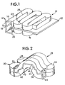
- a basic tool is generally illustrated at 10 as comprising a split serpentine waveguide 12 including an upper section 14 and a lower section 16 which are basically mirror images of each other and which are separated by a gap 18 and are provided with a microwave input coupling 20.
- the waveguide 14 comprises a top wall 24 and sidewalls 26 forming the serpentine structure.
- a composite material in the form of a web 22 is located in the gap 18 for the application for microwave energy thereto.
- a structure of the type which was employed for testing the invention is generally illustrated at 28 as comprising a split microwave waveguide 30 having an upper section which comprises a sidewall 32 and a top wall 34.
- the sidewalls 32 are shaped to conform to the profile of a mold as illustrated at 36 and 38, the mold includes an inner surface 40 and an inner surface 42 which conform to the shape of a preform to be molded.
- the material carrying the surfaces 40 and 42 and any support material between those surfaces and the waveguide are transparent to microwave energy.
- the waveguide is provided in sections and include couplings to each other and for the input of microwave energy as illustrated at 44.
- the composite material of reinforced material and binder resin is shown between the surfaces 40 and 42 at 46. With the composite material 46 loaded into the mold portion of the tool, microwave energy is applied to activate the binder resin for curing.
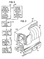
- a typical process for practicing the invention is illustrated at 48 as comprising a step 50 of stacking layers of reinforcing material (fiberglass mat) and uncured rigidizing material (binder resin) in which the layers are formed by applying binder resin to the reinforcement material or, in the alternative, the step 52 of spraying uncured rigidizing material onto a mat of reinforcing material.
- blanks are cut at 54 to conform to the shape of a planar development of the preform.
- the blank is pressed in the mold into the shape of the preform and microwave energy is applied at 58 to cause curing of the binder.
- the binder is cured and rigid, and the rigidized preform may be removed from the mold.
- FIG. 4 illustrates a similar process using robots for handling the material between processing stations.
- the first step is to precut a reinforcement material mat to conform to the developed shape of a preform, as indicated by the die cutter 62.
- a binder is added at 64 in a binder applicator 66 which comprises a source of binder resin 68 and a source of a catalytic promoter 70.
- the binder may be applied in the binder applicator 66 by spraying, rolling or calendaring.
- the composite blank of reinforcement material and binder is transferred from the binder applicator to a mold 72 by a robot 74.
- the mold 72 may be of the type illustrated in FIG.
- the mold 72 is then moved along a shuttle 78 to a press 76 where the two halves of the mold are pressed to replicate the desired shape of the preform and energy is applied from a directed energy source 80 such as a source of microwave energy.
- a directed energy source 80 such as a source of microwave energy.
- the mold 72 is unloaded by moving the same along the shuttle 78 to a position where a robot 82 unloads the cured preform 84.
- the preform becomes a carrier preform in that reinforcement is to be added in the form of a reinforcing structure.
- the robot 82 will then stack the preform for short term storage or move it directly into the energetic stitching process.
- the reinforcement material is precut, as before, at 86 and a robot 88 positions the precut material over a former 90 so that it takes a reinforcement shape 92.
- a robot 94 then retrieves a preform 84, now a carrier preform, and places the same over the formed element 92.
- the carrier preform 84 and the formed element 92 engage in intimate contact.
- the element 92 comprises a binder resin.
- an ultraviolet sensitive binder resin is applied at specific spot locations where the elements 84 and 92 are in intimate engagement. Ultraviolet energy is then applied to cure and bond.
- a directed energy source 96 is then employed to cure the binder and bond the two elements together to form a reinforced structure 98.
- the structure 98 is then transferred to a molding process for molding of the finished structure.
- attachments may be bonded to a carrier preform to increase structural strength of the molded end product or to add attachment devices for the molded end product by the energetic stitching of elements to the preforn. It is not necessary that one element to be attached to another be made by the same energy directed process, or at all by an energy directed process.
- One element may be attached to another by the application of a microwave-sensitive or ultraviolet-sensitive binder resin and the application of the corresponding energy to cure that binder resin. Therefore, this flexibility is an advantage of the energetic stitching process in that a preform made by the microwave technique may have a reinforcement element by energetic stitching using the ultraviolet technique and vice-versa.
- elements such as wood, steel, carbon black and the like may be attached to a preform by using either technique in combination with the appropriate binder resin.
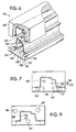
- a tool is illustrated at 100 as comprising a pair of separable mold sections including a shaped member 102 having a shaped member 104 complementary thereto.
- the shaped members 102, 104 are made of a microwave transparent material and form the inner surfaces of a mold cavity.
- the remainder of the mold is formed thereover and may comprise, an outer layer 106, 108, a plurality of waveguide sections 110 connected into a serpentine waveguide by way of a plurality of radius sections 112. When the two sections are brought together, a complete waveguide is formed and there is a space between the layers 102 and 104 defining the mold cavity.
- the mold may include support material, such as wood, foam or resin.
- a binder resin that is molecularly sensitive to ultraviolet radiation is applied to glass fiber reinforcement material.
- the reinforcement material in turn, is placed into a forming mold that is fabricated to conform to the shape of a finished part.
- the fibrous material conforms to the shape of the mold.
- the surfaces of the corresponding halves of the shaping mold in contact with the fibrous material are made of a material that transmits ultraviolet radiation.
- This material can be a solid transparent acrylic type thermoplastic or a metal wire mesh screen.
- the ultraviolet light source is therefore placed within the tooling structure to direct the radiation through the mold surface and at the fibrous material. For simple tooling, the light source is placed into an open chamber below the mold surface. For more complex preform shape requirements, where structural support to the mold surface is required, ultraviolet light sources are placed in multiple chamber sections and energize simultaneously to perform the rigidizing operation.
- binder resins may be employed in the ultraviolet technique. These are available from Freeman Chemical and are known as 80497 (slow system), 747-10 (medium system) and 19-4837 (fast system). Application is similar to that in the microwave technique.
- a tool for the ultraviolet process is illustrated at 118 as comprising an upper mold part 120 and a lower mold part 122.
- the mold surfaces are respectively shown at 124, 126.
- a chamber 128 is formed by the mold part 126 in the lower mold part 122 and has mounted therein a plurality of ultraviolet sources 130--140.
- a composite material is made to conform to the shape defined by the mold surfaces 124, 126 and is rigidized in that shape by the application of ultraviolet energy from the sources 130--140.
- FIGS. 8 and 9 another tool is illustrated at 144 as comprising an upper mold part 146 and a lower mold part 148.
- the upper mold part comprises a sidewall 150, a sidewall 152, an upper wall 154 and an inner wall which is completed by a mold wall 160.
- the lower tool part 148 there is a lower wall 170 and an inner wall which is completed by the mold wall 172.
- the walls In the uppermost part, the walls generally define a chamber 164 on both sides of the mold wall 160. Ultraviolet sources 166 and 168 are mounted in the chamber 164. In the lowermost part 148, the bottom wall 170 and the mold wall 172 define a chamber 174. An ultraviolet source 176 is mounted in the chamber 174.
- a composite material may be subjected to ultraviolet radiation by way of the ultraviolet sources 166, 168 and 176.
Landscapes
- Physics & Mathematics (AREA)
- Electromagnetism (AREA)
- Engineering & Computer Science (AREA)
- Health & Medical Sciences (AREA)
- Mechanical Engineering (AREA)
- Oral & Maxillofacial Surgery (AREA)
- Composite Materials (AREA)
- Toxicology (AREA)
- Chemical & Material Sciences (AREA)
- Thermal Sciences (AREA)
- Reinforced Plastic Materials (AREA)
- Casting Or Compression Moulding Of Plastics Or The Like (AREA)
- Processing And Handling Of Plastics And Other Materials For Molding In General (AREA)
- Moulding By Coating Moulds (AREA)
- Injection Moulding Of Plastics Or The Like (AREA)
- Sampling And Sample Adjustment (AREA)
- Blow-Moulding Or Thermoforming Of Plastics Or The Like (AREA)
Claims (16)
- Procédé de fabrication d'une préforme rigide (84), comprenant les étapes consistant à :- former une ébauche de préforme (54) de forme prédéterminée à partir de fibres de matériau de renforcement,- appliquer une résine de liant (64-68) à l'ébauche, et- faire durcir le liant pour terminer la préforme mise en forme (84),
procédé caractérisé par les étapes consistant à appliquer une résine de liant (64) durcissable par l'application d'énergie électromagnétique (58), et appliquer de l'énergie électromagnétique dirigée (58) n'affectant la résine de liant que pour rigidifier cette résine de liant et faire durcir le liant de manière à terminer la préforme mise en forme (84). - Procédé selon la revendication 1, caractérisé en ce qu'il comprend les étapes consistant à :- former l'ébauche de préforme en découpant une ébauche (54) de forme prédéterminée dans une natte de matériau de renforcement,- appliquer une résine de liant (64) à l'ébauche,- mettre en forme l'ébauche (56) pour lui donner la forme de la préforme (84) ; et- appliquer de l'énergie électromagnétique (58) à l'ébauche mise en forme, pour rigidifier la résine de liant.
- Procédé selon la revendication 1, caractérisé en ce qu'il comprend les étapes consistant à :- appliquer une résine de liant (64) à un renforcement de fibres de verre pour former une ébauche composite (46),- presser l'ébauche composite (46) pour lui donner une forme prédéterminée (56), et- appliquer de l'énergie ultraviolette (130-140, 166, 168, 176) à l'ébauche comprimée (56) pour polymériser la résine de liant et rigidifier l'ébauche comprimée (56) en une préforme rigide (84).
- Procédé selon la revendication 1, caractérisé en ce qu'il comprend les étapes consistant à :- fabriquer une préforme rigidifiée (84) à partir d'un produit composite (46) d'une ébauche souple (54) de matériau de renforcement et d'un matériau de rigidification non durci,- presser l'ébauche (54) dans un moule (36, 38, 72) pour lui donner la forme de la préforme (84), et- appliquer de l'énergie électromagnétique (58) à l'ébauche (54) pendant qu'elle se trouve dans le moule (36, 38, 72), de manière à faire durcir le matériau de rigidification.
- Procédé selon la revendication 4, caractérisé en ce qu'il comprend les étapes consistant à :- appliquer une couche de matériau de rigidification non durci à une couche de matériau de renforcement souple pour former une structure de couche imprégnée,- découper une ébauche (54) dans la structure de couche imprégnée,- presser l'ébauche (56) dans un moule (100) ayant une cavité de moule (102, 104) de la taille et de la forme de la préforme (84), et- appliquer de l'énergie ultraviolette (130-140, 166, 168, 176) à l'ébauche comprimée (56), pendant qu'elle se trouve dans le moule (100), pour faire durcir et rigidifier le matériau de rigidification.
- Procédé selon la revendication 1, caractérisé en ce qu'il comprend les étapes consistant à :- découper une ébauche (54) dans une natte de matériau de renforcement,- appliquer une résine de liant (64) à l'ébauche (54),- placer l'ébauche (54) entre deux parties d'un moule (36, 38, 72),- faire aller et venir le moule dans une presse (76),- presser ensemble les deux parties de moule (32, 38) ;- appliquer de l'énergie électromagnétique (58) à l'ébauche (54) pendant le pressage, pour rigidifier la résine de liant,- faire aller et venir le moule (36, 38, 72) hors de la presse (76), et- retirer la préforme rigide (84) du moule (36, 38, 72).
- Procédé selon l'une ou plusieurs des revendications 1 à 6, caractérisé en ce qu'il comprend les étapes consistant à :- attacher un élément de renforcement à une porteuse de préforme (84), appliquer en des emplacements ponctuels une résine de liant sensible à l'énergie électromagnétique, sur l'élément de renforcement,;- amener l'élément de renforcement en contact intime avec la porteuse de préforme (84) à l'endroit des emplacements ponctuels, et- appliquer de l'énergie électromagnétique (96) aux emplacements ponctuels de l'élément de renforcement, de manière à rigidifier la résine de liant et à souder l'élément de renforcement à la porteuse de préforme (84).
- Procédé selon la revendication 7, caractérisé en ce qu'il comprend les étapes consistant à :- appliquer en des emplacements ponctuels une résine de liant sensible aux micro-ondes, sur l'élément de renforcement,- amener l'élément de renforcement en contact intime avec la préforme porteuse (84) à l'endroit des emplacements ponctuels, et- appliquer de l'énergie micro-ondes (96) aux emplacements ponctuels de l'élément de renforcement, de manière à rigidifier la résine de liant et à souder l'élément de renforcement à la porteuse de préforme (84).
- Procédé selon la revendication 7, caractérisé en ce qu'il comprend les étapes consistant à :- appliquer en des emplacements ponctuels une résine de liant sensible aux ultraviolets , sur l'élément de renforcement ;- amener l'élément de renforcement en contact intime avec la préforme porteuse (84) à l'endroit des emplacements ponctuels, et- appliquer de l'énergie ultraviolette aux emplacements ponctuels de l'élément de renforcement, de manière à rigidifier la résine de liant et à souder l'élément de renforcement à la porteuse de préforme (84).
- Procédé selon l'une ou plusieurs des revendications 1 à 9, caractérisé en ce qu'il comprend les étapes consistant à :- fabriquer une première préforme (84) dont les fibres sont jointes à leurs points de jonction par un liant,- appliquer une résine de liant (64-68) sensible à l'énergie micro-ondes, à un emplacement de la préforme (84) où une section de renforcement ou une préforme supplémentaire (98) doivent être attachées,- positionner la section de renforcement de la préforme supplémentaire (98) contre la première préforme (84) à l'endroit de l'emplacement ci-dessus ; et- appliquer de l'énergie micro-ondes dirigée (58) à l'endroit de l'emplacement de façon que la résine de liant soit activée et que la première préforme (84) ainsi que le renforcement ou préforme supplémentaire (98) soient suturés ensemble ou soudés par points énergétiquement.
- Procédé selon l'une ou plusieurs des revendications 1 à 9, caractérisé en ce qu'il comprend les étapes consistant à :- fabriquer une première préforme (84) comportant des fibres jointes à leurs points de jonction par un liant,- appliquer une résine de liant (64-68) sensible à l'énergie ultraviolette, à un emplacement de la préforme (84) où une section de renforcement ou une préforme supplémentaire (98) doivent être attachés,- positionner la section de renforcement de la préforme supplémentaire (98) contre la première préforme (84) à l'endroit de l'emplacement ci-dessus, et- appliquer de l'énergie ultraviolette dirigée (130-140, 166, 168, 176) sur l'emplacement de façon que la résine de liant soit activée et que la première préforme (84) ainsi que le renforcement ou préforme supplémentaire (98) soient suturés ensemble ou soudés par points énergétiquement.
- Outil de moulage (28, 100, 118, 144) pour fabriquer une préforme (84), comprenant :- un moule (100) comportant une cavité de forme prédéterminée, ce moule (28, 100, 118, 144) comprenant une première partie de moule et une seconde partie de moule séparables (32, 38, 102, 104, 106, 108) définissant chacune une partie de la cavité de moule, outil de moulage caractérisé en ce qu'il comprend un guide d'ondes séparable (30, 110, 112) constitué d'une première partie et d'une seconde partie (32, 34, 110, 112), la première partie de moule (108) servant de montage à la première partie de guide d'ondes (110) et la seconde partie de moule (106) servant de montage à la seconde partie de guide d'ondes (112), tandis qu'une source (80) d'énergie micro-ondes est couplée au guide d'ondes (30, 110, 112).
- Outil de moulage selon la revendication 12, présentant une forme en trois dimensions prédéterminée obtenue à partir d'un matériau composite (46) constitué d'un matériau de renforcement et d'un matériau de rigidification, comprenant : une première partie de moule et une seconde partie de moule séparables (102, 104, 120, 122) pour recevoir le matériau composite (46) entre elles, comprenant des surfaces de moule séparables en coopération (102, 104, 124, 126) qui, lorsqu'elles sont jointes, constituent la forme en trois dimensions prédéterminée ; et un guide d'ondes de micro-ondes comprenant une première partie et une seconde partie (110, 112), la première partie (106) étant portée par la première partie de moule (108) et la seconde partie (112) étant portée par la seconde partie de moule (106), tandis qu'on peut exciter le guide d'ondes pour produire le durcissement du matériau de rigidification.
- Appareil de fabrication de préformes rigides (84), comprenant : des moyens de coupe (62) pour couper une natte de renforcement en fibres de verre de manière à obtenir des ébauches (54) de forme prédéterminée ; un applicateur de liant (66) pour appliquer une résine de liant aux ébauches (54) de manière à former des ébauches composites (46) de matériau de renforcement et de matériau de résine de liant ; des moyens de moule (36, 38, 72) comprenant une première partie de moule et une seconde partie de moule séparables (40, 42) définissant ensemble une cavité de moule destinée à recevoir et à presser un matériau de renforcement portant une résine de liant, appareil caractérisé en ce qu'il comprend : un guide d'ondes de micro-ondes (30) constitué d'une première et d'une seconde section de guide d'ondes séparables (32, 38), la première section (32) étant montée sur la première partie de moule (40) et la seconde section (38) étant montée sur la seconde partie de moule (42), en comprenant une entrée de micro-ondes ; des moyens de chargement (74) pour placer une ébauche composite (46) de matériau de renforcement et de résine de liant dans la cavité de moule (72) ; une presse (76) pour presser les parties de moule (40, 42) ensemble de façon que l'ébauche (46) reproduise la forme de la préforme (84) ; une navette (78) pour faire entrer et sortir le moule (72) de la presse (76) ; des moyens de générateur micro-ondes (80) destinés à se brancher à l'entrée de micro-ondes pour exciter le guide d'ondes de micro-ondes (30) et pour faire durcir et rigidifier la résine de liant ; et des moyens de déchargement (94) pour retirer la préforme rigide (84) du moule (72).
- Appareil selon la revendication 14, comprenant : des moyens pour fabriquer une ébauche de préforme (54) de forme prédéterminée, à partir de fibres d'un matériau de renforcement ; des moyens pour appliquer une résine de liant (64-68) à l'ébauche (54), cette résine étant durcissable par application d'énergie micro-ondes (58) lorsque le liant mouille les fibres de l'ébauche (54) ; et des moyens (80) pour appliquer de l'énergie micro-ondes dirigée (58) n'affectant que la résine de liant pour rigidifier cette résine de liant et pour faire durcir le liant afin de terminer la préforme formée (84).
- Appareil selon la revendication 14, comprenant : des moyens pour appliquer une résine de liant (64-68) à l'ébauche (54), cette résine étant durcissable par l'application d'énergie ultraviolette lorsque le liant mouille les fibres de l'ébauche (54) ; et des moyens (130-140, 166, 168, 176) appliquant de l'énergie ultraviolette dirigée n'affectant que la résine de liant pour rigidifier cette résine de liant et faire durcir le liant, afin de terminer la préforme formée (84).
Applications Claiming Priority (2)
| Application Number | Priority Date | Filing Date | Title |
|---|---|---|---|
| US446859 | 1989-12-06 | ||
| US07/446,859 US6001300A (en) | 1989-12-06 | 1989-12-06 | Method for making rigid three-dimensional preforms using directed electromagnetic energy |
Publications (3)
| Publication Number | Publication Date |
|---|---|
| EP0431442A2 EP0431442A2 (fr) | 1991-06-12 |
| EP0431442A3 EP0431442A3 (en) | 1991-09-11 |
| EP0431442B1 true EP0431442B1 (fr) | 1996-02-28 |
Family
ID=23774094
Family Applications (1)
| Application Number | Title | Priority Date | Filing Date |
|---|---|---|---|
| EP90122607A Expired - Lifetime EP0431442B1 (fr) | 1989-12-06 | 1990-11-27 | Procédé et appareil pour la fabrication de préformes |
Country Status (8)
| Country | Link |
|---|---|
| US (3) | US6001300A (fr) |
| EP (1) | EP0431442B1 (fr) |
| JP (1) | JP3185983B2 (fr) |
| KR (1) | KR100193588B1 (fr) |
| AT (1) | ATE134559T1 (fr) |
| CA (1) | CA2030419C (fr) |
| DE (2) | DE431442T1 (fr) |
| ES (1) | ES2025047T3 (fr) |
Cited By (1)
| Publication number | Priority date | Publication date | Assignee | Title |
|---|---|---|---|---|
| DE102010010802A1 (de) | 2010-03-09 | 2011-09-15 | Fraunhofer-Gesellschaft zur Förderung der angewandten Forschung e.V. | Verfahren zur Herstellung von faserverstärkten Polymer-Formteilen |
Families Citing this family (61)
| Publication number | Priority date | Publication date | Assignee | Title |
|---|---|---|---|---|
| DE69304042T2 (de) * | 1990-07-12 | 1996-12-19 | C A Lawton Co | Verfahren und Vorrichtung zur Herstellung von strukturellen verstärkten Vorformlingen, mit energetischen temporären Verkleben oder Heften |
| US5192387A (en) * | 1990-11-05 | 1993-03-09 | The C.A. Lawton Company | Method of making preforms |
| US5217654A (en) * | 1992-01-30 | 1993-06-08 | The C. A. Lawton Company | Two-stage mat forming preforming and molding process |
| ZA93819B (en) * | 1992-02-24 | 1993-10-15 | Cook Composites & Polymers | Process of making a rigid multi-layer preform |
| US5576358A (en) * | 1995-02-03 | 1996-11-19 | Alliedsignal Inc. | Composition for use in friction materials and articles formed therefrom |
| ATE213211T1 (de) * | 1997-04-17 | 2002-02-15 | Gruppo X Di X Gruppo S R L | Verfahren zur herstellung eines formstabilen wegwerfbehälters und behälter |
| US6280550B1 (en) * | 1998-12-15 | 2001-08-28 | General Electric Company | Fabrication of composite articles having an infiltrated matrix |
| US6692603B1 (en) * | 1999-10-14 | 2004-02-17 | Kimberly-Clark Worldwide, Inc. | Method of making molded cellulosic webs for use in absorbent articles |
| US6617490B1 (en) | 1999-10-14 | 2003-09-09 | Kimberly-Clark Worldwide, Inc. | Absorbent articles with molded cellulosic webs |
| US6478926B1 (en) | 2000-03-31 | 2002-11-12 | Solectria Corporation | Apparatus and method for forming structural preforms |
| DE10035237C1 (de) * | 2000-07-20 | 2001-09-06 | Daimler Chrysler Ag | Verfahren und Produktionsanlage zum Herstellen von schalenförmigen, fasermatten-verstärkten Kunststoffteilen |
| US6331028B1 (en) * | 2000-10-17 | 2001-12-18 | Advance Usa, Inc. | Fiber-reinforced composite structure |
| US6627018B1 (en) | 2000-10-17 | 2003-09-30 | Advance Usa, Llc | System and method of forming composite structures |
| ITVE20010026A1 (it) * | 2001-05-18 | 2002-11-18 | Giorgio Trani | Film flessibile strutturalmente modificabile, per realizzare oggetti dimensionalmente e strutturalmente stabili, in particolare contenitori |
| US20030062637A1 (en) * | 2001-10-02 | 2003-04-03 | Alden John C. | Method and apparatus for recoating optical fiber |
| US20030118761A1 (en) | 2001-12-21 | 2003-06-26 | Kimberly-Clark Worldwide, Inc. | Elastomeric articles having improved chemical resistance |
| US7799968B2 (en) | 2001-12-21 | 2010-09-21 | Kimberly-Clark Worldwide, Inc. | Sponge-like pad comprising paper layers and method of manufacture |
| US20040077943A1 (en) * | 2002-04-05 | 2004-04-22 | Meaney Paul M. | Systems and methods for 3-D data acquisition for microwave imaging |
| US7164105B2 (en) * | 2002-04-05 | 2007-01-16 | Microwave Imaging Systems Technologies, Inc. | Non-invasive microwave analysis systems |
| US20030196743A1 (en) * | 2002-04-17 | 2003-10-23 | Vincent Borbone | Apparatus and methods for producing tow based patterns |
| US7994079B2 (en) | 2002-12-17 | 2011-08-09 | Kimberly-Clark Worldwide, Inc. | Meltblown scrubbing product |
| US6878238B2 (en) | 2002-12-19 | 2005-04-12 | Kimberly-Clark Worldwide, Inc. | Non-woven through air dryer and transfer fabrics for tissue making |
| US6875315B2 (en) | 2002-12-19 | 2005-04-05 | Kimberly-Clark Worldwide, Inc. | Non-woven through air dryer and transfer fabrics for tissue making |
| US7144536B2 (en) * | 2003-04-10 | 2006-12-05 | Owens Corning Fiberglas Technology, Inc. | Methods for making pluralities of air diffusers from a single blank |
| US7052642B2 (en) | 2003-06-11 | 2006-05-30 | Kimberly-Clark Worldwide, Inc. | Composition for forming an elastomeric article |
| US7112299B2 (en) * | 2003-07-09 | 2006-09-26 | Michael Merrick | Systems and methods for fabricating composite fiberglass laminate articles |
| US7141142B2 (en) | 2003-09-26 | 2006-11-28 | Kimberly-Clark Worldwide, Inc. | Method of making paper using reformable fabrics |
| GB2407761A (en) * | 2003-11-04 | 2005-05-11 | Braitrim | Injection moulded garment hanger having an inverted J-shape transverse cross-section |
| EP1559533B1 (fr) * | 2004-01-28 | 2010-06-02 | Lightweight Structures B.V. | Procédé pour la fabrication de preformes de matière fibreuse en feuille |
| GB0425130D0 (en) * | 2004-11-13 | 2004-12-15 | Alderley Materials Ltd | Composite material formation |
| FR2879498B1 (fr) * | 2004-12-16 | 2009-01-30 | Snecma Propulsion Solide Sa | Densification de structures fibreuses par rtm pour la realisation de pieces en materiau composite |
| US20070023975A1 (en) * | 2005-08-01 | 2007-02-01 | Buckley Daniel T | Method for making three-dimensional preforms using anaerobic binders |
| US7842209B2 (en) * | 2006-02-21 | 2010-11-30 | The Boeing Company | Vacuum debulk and radiation cure method |
| US7955548B2 (en) * | 2006-04-13 | 2011-06-07 | American Gfm Corporation | Method for making three-dimensional preforms using electroluminescent devices |
| WO2008140567A2 (fr) * | 2006-11-15 | 2008-11-20 | Honeywell International Inc. | Traitement par micro-ondes de matériaux composites pare-balles |
| US20080290547A1 (en) * | 2007-05-25 | 2008-11-27 | Kashikar Sanjay P | Methods of forming muffler preforms |
| US7809230B2 (en) | 2007-09-25 | 2010-10-05 | Ksaria Corporation | Apparatus for shaping the end of an optical fiber |
| DE102007050312A1 (de) * | 2007-10-18 | 2009-04-23 | Deutsches Zentrum für Luft- und Raumfahrt e.V. | Verfahren zum Herstellen eines Faserverbundbauteils |
| WO2009058500A1 (fr) * | 2007-11-01 | 2009-05-07 | Lockheed Martin Corporation | Raidissage hautement personnalisé pour des composites avancés |
| FR2932410B1 (fr) * | 2008-06-11 | 2010-05-28 | Aircelle Sa | Procede de fabrication d'une piece a corps creux en materiau composite |
| DE102008029058A1 (de) * | 2008-06-18 | 2009-12-24 | GKN Aerospace Services Limited, East Cowes | Verfahren und Formwerkzeug zur Herstellung von Bauteilen aus faserverstärktem Verbundwerkstoff mit Mikrowellen |
| DE102008057403A1 (de) * | 2008-11-14 | 2010-05-20 | Krones Ag | Vorrichtung und Verfahren zum Herstellen von Kunststoffbehältnissen |
| US8268226B2 (en) * | 2009-07-07 | 2012-09-18 | The Boeing Company | Curing system and method using electromagnetic force and conductive heat transfer |
| US8254738B2 (en) | 2010-08-27 | 2012-08-28 | Ksaria Corporation | Methods and systems for efficient installation of cables in watercraft |
| FI20115323A7 (fi) * | 2011-04-04 | 2012-10-05 | Paroc Group Oy | Laitteisto ja menetelmä mineraalivillaa olevien putkieristyskourujen muodostamiseen |
| US9239428B2 (en) | 2011-09-28 | 2016-01-19 | Ksaria Corporation | Epoxy dispensing system and dispensing tip used therewith |
| US9561621B2 (en) * | 2012-05-21 | 2017-02-07 | GM Global Technology Operations LLC | Method and apparatus to mitigate the bond-line read-out defect in adhesive-bonded composite panels |
| GB201315084D0 (en) * | 2013-08-23 | 2013-10-09 | Pentaxia Ltd | Microwave curing of composite materials |
| CN103920809B (zh) * | 2014-04-15 | 2016-12-07 | 重庆市科学技术研究院 | 利用微波能量均匀制热生产弧形部件的装置 |
| DE102014018934A1 (de) * | 2014-12-22 | 2016-06-23 | Airbus Defence and Space GmbH | Vorrichtung zum Aufheizen eines Verbundwerkstoffs mit temperaturabhängigen Verarbeitungseigenschaften und damit zusammenhängende Verfahren |
| US20170057119A1 (en) * | 2015-08-26 | 2017-03-02 | Triumph Integrated Aircraft Interiors, Inc. | Automated press cell system and methods of using the same for forming composite materials |
| CN105415715B (zh) * | 2016-01-15 | 2017-07-18 | 中南大学 | 一种微波自动加热装置及方法 |
| CN105619848B (zh) * | 2016-01-15 | 2018-02-09 | 中南大学 | 一种微波加热装置及方法 |
| CN105666896B (zh) * | 2016-01-15 | 2017-08-25 | 中南大学 | 一种复合能场加热方法 |
| US10571892B2 (en) | 2016-02-02 | 2020-02-25 | The Boeing Company | Preform fabrication system |
| AT519830B1 (de) * | 2017-04-12 | 2019-07-15 | Engel Austria Gmbh | Verfahren zur Herstellung eines konsolidierten mehrlagigen Halbzeugs |
| US11472073B2 (en) * | 2018-04-11 | 2022-10-18 | Sunko Ink Co., Ltd. | Microwave-transmitting mould structure and method for using the same |
| WO2020123145A1 (fr) * | 2018-11-30 | 2020-06-18 | Arris Composites Inc. | Pièces composites renforcées par des fibres, moulées par compression et procédés de fabrication |
| DK4067038T3 (en) | 2021-04-01 | 2025-11-03 | Siemens Gamesa Renewable Energy As | Method for manufacturing of a pre-form part for a wind turbine blade and mould for the manufacturing of a pre-form part |
| CN113296184B (zh) * | 2021-06-22 | 2022-05-17 | 桂林电子科技大学 | 一种基于余弦弯曲的桥型交叉结构的聚合物微纳光纤 |
| KR102685833B1 (ko) * | 2022-03-14 | 2024-07-16 | 주식회사 성일 | Grp 물탱크 판넬 성형장치 |
Family Cites Families (118)
| Publication number | Priority date | Publication date | Assignee | Title |
|---|---|---|---|---|
| US2129711A (en) * | 1933-03-16 | 1938-09-13 | American Telephone & Telegraph | Guided transmission of ultra high frequency waves |
| US2129712A (en) * | 1933-12-09 | 1938-09-13 | American Telephone & Telegraph | Transmission of energy effects by guided electric waves in a dielectric medium |
| GB611708A (en) * | 1944-03-17 | 1948-11-03 | Columbian Rope Co | A method of producing shaped articles from a plastic composition |
| US2560903A (en) * | 1949-08-27 | 1951-07-17 | Raytheon Mfg Co | Wave guide dielectric heating apparatus |
| US2865790A (en) * | 1955-08-19 | 1958-12-23 | Carl A Baer | Method of treating fibrous material utilizing a radio-frequency field which extends predominantly at right angles to the length of said material |
| US3097125A (en) * | 1960-02-02 | 1963-07-09 | Plastic Age Sales Inc | Method of fabricating a glass fiber reinforced plastic luminaire globe |
| BE632793A (fr) * | 1960-06-20 | 1900-01-01 | ||
| US3207819A (en) * | 1961-07-13 | 1965-09-21 | Miller Hofft Inc | Method of making fibreboard |
| NL284802A (fr) * | 1962-10-26 | |||
| NL290076A (fr) * | 1963-03-11 | |||
| US3271220A (en) * | 1963-04-05 | 1966-09-06 | Chemotronics International Inc | Contacting fiber bonding |
| US3277580A (en) * | 1963-07-05 | 1966-10-11 | Hammtronics Systems Inc | Method and apparatus for drying |
| US3287474A (en) * | 1963-08-20 | 1966-11-22 | Eastman Kodak Co | Method of preparing non-woven fabrics |
| US3356781A (en) * | 1963-10-03 | 1967-12-05 | Johns Manville | Method of transfer molding |
| US3321605A (en) * | 1964-08-06 | 1967-05-23 | Gen Electric | Electronic oven |
| DE1565005C3 (de) * | 1965-03-27 | 1975-06-26 | Philips Patentverwaltung Gmbh, 2000 Hamburg | Hochfrequenzerwärmungsgerät mit Hohlleiter |
| US3412227A (en) * | 1965-11-18 | 1968-11-19 | Tappan Co | Electronic oven protection circuit |
| US3676537A (en) * | 1965-11-18 | 1972-07-11 | Thomas W Winstead | Continuous method of extruding and thero-forming skin-covered foamed thermoplastic articles |
| US3457385A (en) * | 1966-07-07 | 1969-07-22 | Canadian Patents Dev | Apparatus for dielectric heating |
| US3463894A (en) * | 1966-07-08 | 1969-08-26 | Canadian Patents Dev | Microwave drying system using phase shifters |
| GB1172228A (en) * | 1966-11-10 | 1969-11-26 | Hirst Microwave Heating Ltd | Microwave Heating Device |
| US3566447A (en) * | 1967-02-06 | 1971-03-02 | British Industrial Plastics | Moulding equipment |
| US3471672A (en) * | 1967-04-28 | 1969-10-07 | Varian Associates | Slotted waveguide applicator |
| US3474210A (en) * | 1967-07-13 | 1969-10-21 | Cryodry Corp | Access opening construction for microwave chambers |
| US3449836A (en) * | 1967-10-25 | 1969-06-17 | Bechtel Int Corp | Air suspension system in microwave drying |
| US3507050A (en) * | 1967-11-14 | 1970-04-21 | Cryodry Corp | Method and apparatus for drying sheet materials |
| US3475827A (en) * | 1967-12-06 | 1969-11-04 | Bechtel Int Corp | R.f. seal in microwave drier |
| FR1593575A (fr) * | 1968-09-17 | 1970-06-01 | ||
| US3666600A (en) * | 1969-03-10 | 1972-05-30 | North American Rockwell | Apparatus for forming layup laminate |
| US3684645A (en) * | 1969-03-25 | 1972-08-15 | Ppg Industries Inc | Glass fiber reinforced thermoplastic article |
| US3632945A (en) * | 1969-04-16 | 1972-01-04 | Cryodry Corp | System and method for heating material employing oversize waveguide applicator |
| US3597567A (en) * | 1969-09-24 | 1971-08-03 | Ray M Johnson | Microwave applicator for heating continuous web |
| US3622733A (en) * | 1970-01-28 | 1971-11-23 | Cryodry Corp | Method and apparatus for drying sheet materials |
| US3713962A (en) * | 1970-03-25 | 1973-01-30 | Ppg Industries Inc | Composite mat structure |
| US3669813A (en) * | 1970-03-31 | 1972-06-13 | Alfred Andrea | Auto body sectional shaping forms |
| US3859409A (en) * | 1970-04-27 | 1975-01-07 | Fibergrate Corp | Method of making a fiber reinforced plastic article |
| US3878019A (en) * | 1970-05-19 | 1975-04-15 | Ici Ltd | Process of producing spot bonded non-woven webs using ultra-violet radiation |
| US3796617A (en) * | 1970-06-05 | 1974-03-12 | Structural Fibers | Method for making fibrous preform |
| US3773638A (en) * | 1970-06-18 | 1973-11-20 | Atomic Energy Res Inst | Process for the radiation curing of unsaturated polyester resins in the presence of sulfur-vulcanized elastomer |
| US3765998A (en) * | 1971-01-11 | 1973-10-16 | Allied Chem | Shapable fiber-reinforced low molecular weight polyethylene terephthalate |
| US3790744A (en) * | 1971-07-19 | 1974-02-05 | American Can Co | Method of forming a line of weakness in a multilayer laminate |
| US3850723A (en) * | 1971-09-20 | 1974-11-26 | Ppg Industries Inc | Method of making a stampable reinforced sheet |
| US3802307A (en) * | 1972-02-22 | 1974-04-09 | Smithe Machine Co Inc F L | Method and apparatus for forming envelope blanks from a web |
| GB1422778A (en) * | 1972-04-10 | 1976-01-28 | Ici Ltd | Shaped polymeric articles |
| US3922426A (en) * | 1973-03-16 | 1975-11-25 | Ici America Inc | Method of making filament wound article |
| US4054713A (en) * | 1973-12-28 | 1977-10-18 | Kao Soap Co., Ltd. | Process for preparing glass fiber mats |
| US4012553A (en) * | 1974-08-01 | 1977-03-15 | Minnesota Mining And Manufacturing Company | Resinous repair pad |
| US4042654A (en) * | 1975-03-13 | 1977-08-16 | Eastman Kodak Company | Manufacture of plastic parts by radiation molding |
| US4042655A (en) * | 1975-09-05 | 1977-08-16 | Phillips Petroleum Company | Method for the production of a nonwoven fabric |
| US4092443A (en) * | 1976-02-19 | 1978-05-30 | Ciba-Geigy Corporation | Method for making reinforced composites |
| US4035215A (en) * | 1976-04-05 | 1977-07-12 | Allen Industries, Inc. | Process for making sound insulation components |
| US4146417A (en) * | 1976-05-04 | 1979-03-27 | Johnson & Johnson | Method for producing bonded nonwoven fabrics using ionizing radiation |
| GB1552046A (en) * | 1977-02-02 | 1979-09-05 | Ciba Geigy Ag | Film adhesives |
| SE412504B (sv) * | 1977-04-07 | 1980-03-03 | Inst For Mikrovagsteknik Vid T | Sett och anordning for att medelst mikrovagsenergi astadkomma en i huvudsak likformig uppvermning |
| US4101254A (en) * | 1977-05-27 | 1978-07-18 | Structural Fibers, Inc. | Preform machine |
| GB1587536A (en) * | 1977-07-05 | 1981-04-08 | Ciba Geigy Ag | Expoxide resin-impregnated composites |
| SE420991B (sv) * | 1978-02-13 | 1981-11-16 | Scandinavian Glasfiber Ab | Sett for framstellning av foremal av med glasfibrer armerad herdplast |
| US4265954A (en) * | 1978-04-11 | 1981-05-05 | Phillips Petroleum Company | Selective-area fusion of non-woven fabrics |
| CH652413A5 (fr) * | 1978-09-20 | 1985-11-15 | Deltaglass Sa | Composition adhesive photodurcissable. |
| US4208562A (en) * | 1978-11-17 | 1980-06-17 | Raytheon Company | Cavity feed system |
| US4231825A (en) * | 1979-04-23 | 1980-11-04 | Owens-Corning Fiberglas Corporation | Method of making jacketed foam pipe insulation |
| DE2931737A1 (de) * | 1979-08-04 | 1981-02-26 | Basf Ag | Verfahren zur herstellung von formkoerpern aus ungesaettigten polyesterharzen |
| US4269581A (en) * | 1979-09-14 | 1981-05-26 | Fusion Systems Corporation | Apparatus for molding thermosetting material |
| US4295907A (en) * | 1979-12-28 | 1981-10-20 | Freeman Chemical Corporation | Method of making glass fiber reinforced laminate |
| US4692291A (en) * | 1980-04-14 | 1987-09-08 | Union Carbide Corporation | Molding method using fast curing fiber reinforced, low viscosity thermosetting resin |
| US4352769A (en) * | 1980-05-27 | 1982-10-05 | Victor United, Inc. | Method for simultaneously molding a plurality of products |
| FR2497839A1 (fr) * | 1981-01-12 | 1982-07-16 | Brochier Fils J | Tissu tridimensionnel pour le renforcement de materiaux stratifies et elements en forme obtenus a partir d'un tel tissu |
| US4386042A (en) * | 1981-02-10 | 1983-05-31 | Akinori Tatebayashi | Molding of synthetic resin article having a hard coating |
| DE3109424A1 (de) * | 1981-03-12 | 1982-10-28 | Herbert 7140 Ludwigsburg Schreiber | Verfahren zur herstellung faserverstaerkter kunststoffgegenstaende und prepreg zu seiner durchfuehrung sowie danach hergestellte gegenstaende |
| NO812163L (no) * | 1981-06-24 | 1982-12-27 | Berg Ltd A S Laader | Fremgangsmaate ved fremstilling av fiberarmerte gjenstander, og innretning for utfoerelse av fremgangsmaaten |
| US4410561A (en) * | 1981-07-31 | 1983-10-18 | Bell Telephone Laboratories, Incorporated | Method of forming coated optical fiber |
| DE3367781D1 (en) * | 1982-04-03 | 1987-01-08 | Ciba Geigy Ag | Process for preparing prepregs from fibres that contain cellulose using aqueous resin compositions |
| NZ205990A (en) * | 1982-11-05 | 1987-04-30 | Deltaglass Sa | Radiation-curable, urethane acrylate-containing liquid adhesive composition and glass laminates |
| US4537823A (en) * | 1983-11-18 | 1985-08-27 | Allied Corporation | Method of manufacturing a friction article |
| JPS60135230A (ja) * | 1983-12-22 | 1985-07-18 | Yamamoto Tekkosho:Kk | 加圧真空プレス |
| US4840756A (en) * | 1984-04-27 | 1989-06-20 | E. I. Du Pont Nemours And Company | Radiation process for preparation of electrophoresis gel material |
| JPS6131214A (ja) * | 1984-07-23 | 1986-02-13 | Toyota Motor Corp | 車輛用装飾モ−ルの製造方法 |
| US4568581A (en) * | 1984-09-12 | 1986-02-04 | Collins & Aikman Corporation | Molded three dimensional fibrous surfaced article and method of producing same |
| ATE65745T1 (de) * | 1985-01-26 | 1991-08-15 | Olympia Aeg | Verfahren zum herstellen einer beschriftung auf aus sich bei einwirkung einer laserstrahlung verfaerbendem kunststoff bestehenden tastenknoepfen fuer schreib-oder bueromaschinen. |
| DE3507720C2 (de) * | 1985-03-05 | 1997-08-14 | Rieter Automotive Int Ag | Verfahren und Vorrichtung zum Herstellen eines Rohlings aus glasfaserverstärktem Kunststoff |
| DE3520152A1 (de) * | 1985-06-05 | 1986-12-18 | Ymos Aktiengesellschaft Industrieprodukte, 6053 Obertshausen | Verfahren und vorrichtung zum herstellen einer kunststoffhaut |
| GB8519778D0 (en) * | 1985-08-07 | 1985-09-11 | Ciba Geigy Ag | Moulded composites |
| CA1297835C (fr) * | 1985-09-05 | 1992-03-24 | Toyoda Gosei Co., Ltd. | Appareil et methode de traitement de moulages en resine |
| US4892764A (en) * | 1985-11-26 | 1990-01-09 | Loctite Corporation | Fiber/resin composites, and method of making the same |
| DE3605574A1 (de) * | 1986-02-21 | 1987-08-27 | Basf Ag | Metalldrahteinlagen enthaltende, photopolymerisierbare formmassen |
| US4741873A (en) * | 1986-04-15 | 1988-05-03 | Kaiser Aerotech, A Division Of Sowa & Sons | Method for forming rigid composite preforms |
| JPS62244621A (ja) * | 1986-04-17 | 1987-10-26 | Agency Of Ind Science & Technol | 炭素繊維強化プラスチツクパイプの連続成形方法及びその装置 |
| US4869855A (en) * | 1986-05-02 | 1989-09-26 | Allied Signal Inc. | Method of manufacturing molded articles |
| US4663225A (en) * | 1986-05-02 | 1987-05-05 | Allied Corporation | Fiber reinforced composites and method for their manufacture |
| US4812283A (en) * | 1986-05-02 | 1989-03-14 | Allied-Signal Inc. | Method of manufacture of formed article |
| JPS6319780A (ja) * | 1986-07-10 | 1988-01-27 | 矢崎総業株式会社 | 電線の結合部に被覆層を形成する方法 |
| US4863538A (en) * | 1986-10-17 | 1989-09-05 | Board Of Regents, The University Of Texas System | Method and apparatus for producing parts by selective sintering |
| US4883552A (en) * | 1986-12-05 | 1989-11-28 | Phillips Petroleum Company | Pultrusion process and apparatus |
| DE3780928T2 (de) * | 1986-12-19 | 1992-12-24 | Takeda Chemical Industries Ltd | Verfahren zum gussformen von faserverstaerkten kunststoffen. |
| JP2823016B2 (ja) * | 1986-12-25 | 1998-11-11 | ソニー株式会社 | 透過型スクリーンの製造方法 |
| US4898770A (en) * | 1987-04-07 | 1990-02-06 | Owens-Corning Fiberglas Corporation | Process for producing preformable continuous strand mats using a mixture of thermosetting and thermoplastic resin |
| CH672611A5 (fr) * | 1987-04-30 | 1989-12-15 | Fischer Ag Georg | |
| US4803022A (en) * | 1987-05-06 | 1989-02-07 | Glasteel Industrial Laminates, Inc. | Method of continuously bonding and curing a zinc-coated metal-clad polyester-epoxy-glass fiber laminate |
| US4762740A (en) * | 1987-06-15 | 1988-08-09 | Ford Motor Company | Resin transfer molding core, preform and process |
| US4950439A (en) * | 1987-07-10 | 1990-08-21 | C. H. Masland & Sons | Glossy finish fiber reinforced molded product |
| US4913859A (en) * | 1987-10-30 | 1990-04-03 | At&T Bell Laboratories | Methods of curing optical fiber coatings |
| US4879073A (en) * | 1988-04-22 | 1989-11-07 | United Technologies Corporation | Process of high pressure curing with ultraviolet radiation |
| US4921205A (en) * | 1988-05-17 | 1990-05-01 | Sola Usa, Inc. | Lens mold assembly |
| US4952366A (en) * | 1988-07-25 | 1990-08-28 | Owens-Corning Fiberglas Corporation | Molding process |
| GB8822520D0 (en) * | 1988-09-26 | 1988-11-02 | Tech Textiles Ltd | Process for continuously forming reinforced plastics articles |
| US4921647A (en) * | 1988-10-27 | 1990-05-01 | Shell Oil Company | Method of shaping a laminated thermoplastic billet |
| US4988469A (en) * | 1988-11-21 | 1991-01-29 | United Technologies Corporation | Method of fabricating fiber reinforced composite articles by resin transfer molding |
| US5110514A (en) * | 1989-05-01 | 1992-05-05 | Soane Technologies, Inc. | Controlled casting of a shrinkable material |
| US5041260A (en) * | 1989-10-30 | 1991-08-20 | Ford Motor Company | Resin transfer molding method |
| US5002476A (en) * | 1989-11-24 | 1991-03-26 | Lockheed Corporation | Tooling for composite parts |
| US5073315A (en) * | 1989-12-19 | 1991-12-17 | Bertelson Peter C | Methods for making fiber reinforced wheels and other structural moldings |
| US5318650A (en) * | 1990-06-05 | 1994-06-07 | E. I. Du Pont De Nemours And Company | Bonded fibrous articles |
| US5487853A (en) * | 1990-07-12 | 1996-01-30 | The C. A. Lawton Company | Energetic stitching for complex preforms |
| US5217656A (en) * | 1990-07-12 | 1993-06-08 | The C. A. Lawton Company | Method for making structural reinforcement preforms including energetic basting of reinforcement members |
| US5192387A (en) * | 1990-11-05 | 1993-03-09 | The C.A. Lawton Company | Method of making preforms |
| US5169571A (en) * | 1991-04-16 | 1992-12-08 | The C.A. Lawton Company | Mat forming process and apparatus |
| US5332536A (en) * | 1992-01-22 | 1994-07-26 | Cook Composites And Polymers Co. | Molding resins and UV-transparent molds made from the resins for making fiber reinforced articles |
| US5217654A (en) * | 1992-01-30 | 1993-06-08 | The C. A. Lawton Company | Two-stage mat forming preforming and molding process |
-
1989
- 1989-12-06 US US07/446,859 patent/US6001300A/en not_active Expired - Lifetime
-
1990
- 1990-11-21 CA CA002030419A patent/CA2030419C/fr not_active Expired - Fee Related
- 1990-11-27 EP EP90122607A patent/EP0431442B1/fr not_active Expired - Lifetime
- 1990-11-27 ES ES90122607T patent/ES2025047T3/es not_active Expired - Lifetime
- 1990-11-27 DE DE199090122607T patent/DE431442T1/de active Pending
- 1990-11-27 DE DE69025559T patent/DE69025559T2/de not_active Expired - Fee Related
- 1990-11-27 AT AT90122607T patent/ATE134559T1/de not_active IP Right Cessation
- 1990-11-30 JP JP33084190A patent/JP3185983B2/ja not_active Expired - Fee Related
- 1990-12-04 KR KR1019900019807A patent/KR100193588B1/ko not_active Expired - Fee Related
-
1995
- 1995-03-10 US US08/401,996 patent/US5866060A/en not_active Expired - Lifetime
-
1997
- 1997-11-07 US US08/965,874 patent/US6004123A/en not_active Expired - Lifetime
Cited By (1)
| Publication number | Priority date | Publication date | Assignee | Title |
|---|---|---|---|---|
| DE102010010802A1 (de) | 2010-03-09 | 2011-09-15 | Fraunhofer-Gesellschaft zur Förderung der angewandten Forschung e.V. | Verfahren zur Herstellung von faserverstärkten Polymer-Formteilen |
Also Published As
| Publication number | Publication date |
|---|---|
| DE431442T1 (de) | 1992-01-16 |
| JP3185983B2 (ja) | 2001-07-11 |
| CA2030419A1 (fr) | 1991-06-07 |
| US6001300A (en) | 1999-12-14 |
| ES2025047A4 (es) | 1992-03-16 |
| EP0431442A3 (en) | 1991-09-11 |
| ATE134559T1 (de) | 1996-03-15 |
| KR100193588B1 (ko) | 1999-06-15 |
| EP0431442A2 (fr) | 1991-06-12 |
| KR910011432A (ko) | 1991-08-07 |
| JPH03213310A (ja) | 1991-09-18 |
| US5866060A (en) | 1999-02-02 |
| CA2030419C (fr) | 1998-03-31 |
| ES2025047T3 (es) | 1996-06-01 |
| DE69025559D1 (de) | 1996-04-04 |
| US6004123A (en) | 1999-12-21 |
| DE69025559T2 (de) | 1996-09-12 |
Similar Documents
| Publication | Publication Date | Title |
|---|---|---|
| EP0431442B1 (fr) | Procédé et appareil pour la fabrication de préformes | |
| CA2089826C (fr) | Methode et appareil servant a fabriquer des preformes de piece de renforcement, notamment par le faufilage energetique de bandes de materiau de renforcement et de la piqure energetique d'elements de renforcement | |
| US5487853A (en) | Energetic stitching for complex preforms | |
| US5041260A (en) | Resin transfer molding method | |
| CA2085633C (fr) | Formage et preformage de mats en deux etapes | |
| CA2584581C (fr) | Methode de fabrication de preformes tridimensionnelles au moyen de dispositifs electroluminescents | |
| EP1749631B1 (fr) | Méthode de fabrication de préformes tridimensionnelles en utilisant des liants anaérobies | |
| EP0620091B1 (fr) | Procédé et dispositif pour la manufacture des demi-produits pour renforcement structural, avec collage-temporaire ou fixation énergétique | |
| TW201533109A (zh) | 複合物的一次完成製法 | |
| US7261794B2 (en) | Method and apparatus for bonding a cover to a substrate using high frequency microwaves | |
| JP5340239B2 (ja) | 繊維強化プラスチック成形物の成形方法 | |
| US4995931A (en) | Method for forming components from fibre-reinforced thermoplastic materials | |
| JPH07186281A (ja) | 繊維強化プラスチック成形品の成形方法及びその成形装置 | |
| JPH05147056A (ja) | 繊維強化プラスチツク成形品の成形方法及びその成形装置 | |
| JPH03227210A (ja) | 内装材の製造方法 |
Legal Events
| Date | Code | Title | Description |
|---|---|---|---|
| PUAI | Public reference made under article 153(3) epc to a published international application that has entered the european phase |
Free format text: ORIGINAL CODE: 0009012 |
|
| 17P | Request for examination filed |
Effective date: 19901218 |
|
| AK | Designated contracting states |
Kind code of ref document: A2 Designated state(s): AT DE ES FR GB IT |
|
| PUAL | Search report despatched |
Free format text: ORIGINAL CODE: 0009013 |
|
| AK | Designated contracting states |
Kind code of ref document: A3 Designated state(s): AT DE ES FR GB IT |
|
| TCAT | At: translation of patent claims filed | ||
| EL | Fr: translation of claims filed | ||
| DET | De: translation of patent claims | ||
| 17Q | First examination report despatched |
Effective date: 19930806 |
|
| GRAH | Despatch of communication of intention to grant a patent |
Free format text: ORIGINAL CODE: EPIDOS IGRA |
|
| GRAA | (expected) grant |
Free format text: ORIGINAL CODE: 0009210 |
|
| AK | Designated contracting states |
Kind code of ref document: B1 Designated state(s): AT DE ES FR GB IT |
|
| REF | Corresponds to: |
Ref document number: 134559 Country of ref document: AT Date of ref document: 19960315 Kind code of ref document: T |
|
| ET | Fr: translation filed | ||
| REF | Corresponds to: |
Ref document number: 69025559 Country of ref document: DE Date of ref document: 19960404 |
|
| ITF | It: translation for a ep patent filed | ||
| REG | Reference to a national code |
Ref country code: ES Ref legal event code: FG2A Ref document number: 2025047 Country of ref document: ES Kind code of ref document: T3 |
|
| PLBE | No opposition filed within time limit |
Free format text: ORIGINAL CODE: 0009261 |
|
| STAA | Information on the status of an ep patent application or granted ep patent |
Free format text: STATUS: NO OPPOSITION FILED WITHIN TIME LIMIT |
|
| 26N | No opposition filed | ||
| REG | Reference to a national code |
Ref country code: GB Ref legal event code: IF02 |
|
| PGFP | Annual fee paid to national office [announced via postgrant information from national office to epo] |
Ref country code: ES Payment date: 20061124 Year of fee payment: 17 |
|
| PGFP | Annual fee paid to national office [announced via postgrant information from national office to epo] |
Ref country code: IT Payment date: 20071129 Year of fee payment: 18 Ref country code: AT Payment date: 20071101 Year of fee payment: 18 |
|
| PGFP | Annual fee paid to national office [announced via postgrant information from national office to epo] |
Ref country code: FR Payment date: 20071119 Year of fee payment: 18 |
|
| PGFP | Annual fee paid to national office [announced via postgrant information from national office to epo] |
Ref country code: DE Payment date: 20071221 Year of fee payment: 18 |
|
| REG | Reference to a national code |
Ref country code: ES Ref legal event code: FD2A Effective date: 20071128 |
|
| PG25 | Lapsed in a contracting state [announced via postgrant information from national office to epo] |
Ref country code: ES Free format text: LAPSE BECAUSE OF NON-PAYMENT OF DUE FEES Effective date: 20071128 |
|
| PG25 | Lapsed in a contracting state [announced via postgrant information from national office to epo] |
Ref country code: IT Free format text: LAPSE BECAUSE OF NON-PAYMENT OF DUE FEES Effective date: 20081127 Ref country code: AT Free format text: LAPSE BECAUSE OF NON-PAYMENT OF DUE FEES Effective date: 20081127 |
|
| REG | Reference to a national code |
Ref country code: FR Ref legal event code: ST Effective date: 20090731 |
|
| PG25 | Lapsed in a contracting state [announced via postgrant information from national office to epo] |
Ref country code: DE Free format text: LAPSE BECAUSE OF NON-PAYMENT OF DUE FEES Effective date: 20090603 |
|
| PGFP | Annual fee paid to national office [announced via postgrant information from national office to epo] |
Ref country code: GB Payment date: 20091125 Year of fee payment: 20 |
|
| REG | Reference to a national code |
Ref country code: GB Ref legal event code: PE20 Expiry date: 20101126 |
|
| PG25 | Lapsed in a contracting state [announced via postgrant information from national office to epo] |
Ref country code: GB Free format text: LAPSE BECAUSE OF EXPIRATION OF PROTECTION Effective date: 20101126 |
|
| PG25 | Lapsed in a contracting state [announced via postgrant information from national office to epo] |
Ref country code: FR Free format text: LAPSE BECAUSE OF NON-PAYMENT OF DUE FEES Effective date: 20081130 |