EP0431447B1 - Vorrichtung zur Stabilisierung einer gekerbten Bahn in einem Saugkasten - Google Patents
Vorrichtung zur Stabilisierung einer gekerbten Bahn in einem Saugkasten Download PDFInfo
- Publication number
- EP0431447B1 EP0431447B1 EP90122671A EP90122671A EP0431447B1 EP 0431447 B1 EP0431447 B1 EP 0431447B1 EP 90122671 A EP90122671 A EP 90122671A EP 90122671 A EP90122671 A EP 90122671A EP 0431447 B1 EP0431447 B1 EP 0431447B1
- Authority
- EP
- European Patent Office
- Prior art keywords
- web
- ring
- loop
- chamber
- opening
- Prior art date
- Legal status (The legal status is an assumption and is not a legal conclusion. Google has not performed a legal analysis and makes no representation as to the accuracy of the status listed.)
- Expired - Lifetime
Links
- 239000000463 material Substances 0.000 claims description 30
- 230000000694 effects Effects 0.000 description 5
- 230000007423 decrease Effects 0.000 description 4
- 230000002411 adverse Effects 0.000 description 3
- 238000006748 scratching Methods 0.000 description 3
- 230000002393 scratching effect Effects 0.000 description 3
- 230000000087 stabilizing effect Effects 0.000 description 3
- 238000004804 winding Methods 0.000 description 3
- 229920000728 polyester Polymers 0.000 description 2
- 238000007789 sealing Methods 0.000 description 2
- 238000011144 upstream manufacturing Methods 0.000 description 2
- 239000004677 Nylon Substances 0.000 description 1
- 239000000853 adhesive Substances 0.000 description 1
- 230000001070 adhesive effect Effects 0.000 description 1
- 239000002390 adhesive tape Substances 0.000 description 1
- 238000010276 construction Methods 0.000 description 1
- 238000007599 discharging Methods 0.000 description 1
- 238000002372 labelling Methods 0.000 description 1
- 230000004048 modification Effects 0.000 description 1
- 238000012986 modification Methods 0.000 description 1
- 229920001778 nylon Polymers 0.000 description 1
- 238000000926 separation method Methods 0.000 description 1
- 230000006641 stabilisation Effects 0.000 description 1
- 238000011105 stabilization Methods 0.000 description 1
Images
Classifications
-
- B—PERFORMING OPERATIONS; TRANSPORTING
- B65—CONVEYING; PACKING; STORING; HANDLING THIN OR FILAMENTARY MATERIAL
- B65H—HANDLING THIN OR FILAMENTARY MATERIAL, e.g. SHEETS, WEBS, CABLES
- B65H20/00—Advancing webs
- B65H20/24—Advancing webs by looping or like devices
-
- B—PERFORMING OPERATIONS; TRANSPORTING
- B65—CONVEYING; PACKING; STORING; HANDLING THIN OR FILAMENTARY MATERIAL
- B65H—HANDLING THIN OR FILAMENTARY MATERIAL, e.g. SHEETS, WEBS, CABLES
- B65H23/00—Registering, tensioning, smoothing or guiding webs
- B65H23/04—Registering, tensioning, smoothing or guiding webs longitudinally
- B65H23/042—Sensing the length of a web loop
-
- G—PHYSICS
- G11—INFORMATION STORAGE
- G11B—INFORMATION STORAGE BASED ON RELATIVE MOVEMENT BETWEEN RECORD CARRIER AND TRANSDUCER
- G11B15/00—Driving, starting or stopping record carriers of filamentary or web form; Driving both such record carriers and heads; Guiding such record carriers or containers therefor; Control thereof; Control of operating function
- G11B15/56—Driving, starting or stopping record carriers of filamentary or web form; Driving both such record carriers and heads; Guiding such record carriers or containers therefor; Control thereof; Control of operating function the record carrier having reserve loop, e.g. to minimise inertia during acceleration measuring or control in connection therewith
- G11B15/58—Driving, starting or stopping record carriers of filamentary or web form; Driving both such record carriers and heads; Guiding such record carriers or containers therefor; Control thereof; Control of operating function the record carrier having reserve loop, e.g. to minimise inertia during acceleration measuring or control in connection therewith with vacuum column
-
- B—PERFORMING OPERATIONS; TRANSPORTING
- B65—CONVEYING; PACKING; STORING; HANDLING THIN OR FILAMENTARY MATERIAL
- B65H—HANDLING THIN OR FILAMENTARY MATERIAL, e.g. SHEETS, WEBS, CABLES
- B65H2408/00—Specific machines
- B65H2408/20—Specific machines for handling web(s)
- B65H2408/21—Accumulators
- B65H2408/215—Accumulators supported by vacuum or blown air
-
- B—PERFORMING OPERATIONS; TRANSPORTING
- B65—CONVEYING; PACKING; STORING; HANDLING THIN OR FILAMENTARY MATERIAL
- B65H—HANDLING THIN OR FILAMENTARY MATERIAL, e.g. SHEETS, WEBS, CABLES
- B65H2601/00—Problem to be solved or advantage achieved
- B65H2601/50—Diminishing, minimizing or reducing
- B65H2601/52—Diminishing, minimizing or reducing entities relating to handling machine
- B65H2601/524—Vibration
Definitions
- Vacuum boxes have long been used for applying tension to a loop of a web material, such as webs of paper or photographic film.
- a vacuum box is along the path between a supply of web material and a station where the web material is wound onto a spool.
- a loop of the web material is formed in the vacuum box by applying a vacuum to the bottom of the box, and the vacuum holds the loop in the box under slight tension.
- the web material can be driven out of the box intermittently during the spooling operation, and can be fed into the box from the web supply continuously or on an intermittent basis. It is known to provide sensors to detect the position of the bottom of the loop in the vacuum box and to shut off the drive mechanism between the supply and the vacuum box when the loop reaches a predetermined maximum size.
- the web passing through the vacuum box has one or more notches or other openings in it, the web will vibrate excessively as it passes through the box, and there will be a dramatic loss in tension in the web induced by the vacuum box when the notch passes through the bottom of the loop in the vacuum box.
- the vibration and the loss in tension result from a surge of air flowing through the notch. Such vibrations and the change in web tension are most undesirable and can adversely effect operations downstream of the vacuum box.
- U.S. Patent 2,862,675 issued December 2, 1958 in the name of D. N. McDonald, showing a device according to the preamble of claim 1, discloses a transport system for perforated tapes in which a ring is positioned inside the loop in a vacuum box to cover the perforations in the strip.
- U.S. Patent No. 3,871,597 issued March 18, 1975 in the name of H. LaMers, relates to a labeling apparatus that uses a web carrying a plurality of labels.
- a loop of the web is formed in a chamber, and vacuum is applied to the chamber to draw the web into a supply loop in the chamber.
- a curtain in the chamber maintains the web in the loop configuration.
- the curtain is described as comprising a thin flexible material, such as a 0.005 inch thick sheet of nylon, which is drawn by the vacuum and presses against the web to maintain it as a loop.
- One end of the curtain is fixed to a post while the opposite end is free and in constant engagement with the web.
- the web is prepared with die cuts on the border of each label area to be formed to facilitate separation of the labels from the rest of the web.
- Each label area is defined by a plurality of cuts which form a closed loop that encircles the label area.
- the areas at the edges of the web and outside the label areas have sprocket holes that are spaced along the length of the web.
- the curtain is apparently imperforate and is described as sealing the web area where cuts are made that form the label and sprocket areas.
- the curtain is designed to fill out the full width of the supply chamber when the web is narrower than the chamber, and in addition, it is an opaque material which can be used to interrupt a light beam used for detecting and controlling the size of the loop in the chamber.
- U.S. Patent No. 3,807,612 issued April 30, 1974 in the name of R. H. Eggert relates to a web feeding apparatus for a blank making machine.
- the Eggert patent discloses a vacuum box in which the size of the loop of web material in the box is sensed by a series of lamps and related photo cells.
- the loop control system may be inefficient, imprecise or ineffective.
- an opaque shade of thin flexible material is suspended inside the loop of web material. One end of the shade is secured to a rod and the other end is free to move into engagement with the web loop.
- the shade need only be wide enough to eclipse the photocells from the lamps and hence can have a maximum width that is only somewhat less than the narrowest strip of the web material that is to be drawn into the vacuum box.
- the length of the shade is adequate to reach the bottom of the loop when the loop is enlarged enough the receive light from the lowermost photocell of the system.
- the differential air pressure across the loop causes the shade to substantially conform to the interior surface of the loop.
- the first patented device mentioned above includes a ring within a loop of perforated web.
- the shape of the loop does not change as the loop moves up and down in the vacuum box.
- McDonald's ring need not be flexible to accommadate changes in the shape of the loop.
- a device to stabilize a web with one or more notches or other openings in the web as the web passes through a vacuum box.
- the box has walls defining an elongate chamber for receiving a loop of the web.
- the chamber has an opening through which the web enters and leaves the chamber.
- Vacuum means spaced from the opening draws air through the chamber so that the loop of web is held under tension in the chamber.
- the device according to the invention comprises an endless ring of flexible web material having a plurality of vent holes extending through the ring and spaced from each other. The holes are offset from one side edge of the ring.
- the ring is positionable within the loop of the web and the ring is freely rotated by the web in response to movement of the web through the chamber.
- the portion of the ring between the holes and the one side edge of the ring is imperforate and covers the notch or other opening in the web as it passes the ring so air is not drawn through the notch or opening as it passes the ring.
- the stabilizing device of the invention can be used with webs of various types, including webs of paper or photographic film.
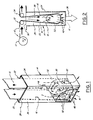
- the device can be used with a paper web 10 delivered from a supply roll 12 initially to a vacuum box generally designated 14 and then to a spooling machine (not shown) at the downstream side of the vacuum box.
- the large arrows at the top of Fig. 2 show the direction of movement of the web into and out of the box 14.
- a paper web 10 conventionally furnished to a spooling machine has a plurality of notches 16 located along a side edge of the web in spaced relation to each other. At the spooling machine the paper web is wound onto a spool along with a strip of photographic film.
- Rolls of film and paper web of this kind are well known and include, for example, size 120 photographic film. While the following description refers specifically to notches in an edge of a web, it will be understood that the invention is applicable to webs having openings of various types in other locations.
- the vacuum box 14 can be of any known construction. For example, it includes four walls 20, 22, 24 and 26 which together define an elongate chamber 28 for receiving a loop of the web 10 as illustrated in Figs. 1 and 2. Chamber 28 has an opening 30 at the top through which the web enters and leaves the chamber. The web can be guided into and out of the chamber by guide members 32, 34 which can comprise rollers, air bars or other known guiding apparatus.
- the guide members are positioned above the opening 30 with a center-to-center distance less than a width of the elongate chamber 28 between the side walls 20, 24, so that the shape of the loop changes as a transverse dimension of the loop between the side walls increases between the opening and the vacuum means.
- a suitable vacuum system shown diagrammatically at 36 in Fig. 2, for drawing air through the opening 30 at the top of the chamber 28 and discharging it through the bottom of the chamber.
- the air flow through opening 30 is illustrated by the arrows 38 and is primarily through the space between the guide members 32, 34 and into the upper part of the loop of web in the box 14.
- the air can travel around the side edges of the web 10 and between the web and walls 22, 26 before it is discharged from the bottom of the vacuum box.
- the space between the walls 22, 26 of the vacuum box is slightly greater than the width of the web 10, and as the air flows through the chamber 28 it places the web 10 under a slight tension. Vacuum boxes of this kind are well known and need not be described in more detail here.
- an endless ring 50 is placed in the loop of web material 10 in the vacuum box.
- the ring has a plurality of vent openings 52 through the central portion of the ring to enable air passing through chamber 28 to flow through the openings.
- the openings can take various shapes, including a plurality of oblong holes, as illustrated, which extend around the circumference of the ring in spaced relation to each other and offset from the side edges of the ring.
- the ring can be fabricated from a flat rectangular strip of material. The ends of the strip of material are cut so that the ends can be butted and secured together to form a smooth splice. The ends can be glued together with an adhesive, or held together by an adhesive tape applied over the abutting ends of the strip.
- the ring is substantially cylindrical in shape before it is inserted into the vacuum box. The ring also can be cast or extruded or drawn into an endless ring shape.
- Ring 50 can be made from various kinds of flexible, imperforate material.
- the ring can be made from a rectangular strip of polyester material which has been extruded through a die and stretched in two directions to cross link molecules of the polyester material.
- a material of this kind is manufactured by the Eastman Kodak Company of Rochester, New York, and sold under the trademark Estar. Estar is a registered trademark of the Eastman Kodak Company. Materials of this kind are used as a film base for some photographic films.
- the ring material selected for use needs to be one which provides some stiffness or beam strength so that the ring will not collapse but maintain a generally cylindrical or oblong shape even after the holes 52 are provided in the ring and when it is subjected to pressure from web 10 in the vacuum box. Factors to be considered for selecting a material used for the ring include the material thickness, the stiffness of the material, its beam strength, and the size and location of the holes 52 relative to each other and relative to the side edges of the ring.
- the width of the ring preferably is equal to or slightly smaller than the width of the web 10.
- the ring also is slightly narrower than the width of the vacuum box 14 between walls 22 and 26 so that the ring does not contact the walls and become misaligned with the web 10.
- Fig. 2 shows the loop of web 10 spaced from walls 20, 24 of the vacuum box.
- the portions of the web near the loop bottom are very close to walls 20, 24.
- the points nearest the walls are referred to as the tangent points.
- the orifice area comprises the area between the side walls of the vacuum box and the loop of web 10 from the tangent points downwardly to the bottom of the web loop.
- holes 52 should be located in the ring so that they do not become aligned with the notches or openings 16 in the web. Thus holes 52 may need to be nearer to one side edge of the ring than the other side edge thereof, depending on the size and location of the notches.
- Ring 50 can be inserted into the vacuum box by deforming it slightly and manually placing it between the guide members 32, 34 after the loop of web material 10 has been formed in the vacuum box. The presence of the ring at this position will cause it to be sucked downwardly into the loop of the web in the vacuum box due to the air flow through the box established by the vacuum means 36.
- the ring will always be in contact with the inner surface of the web 10 and can constantly flex and bend to maintain a shape corresponding to the loop of the web in the vacuum box.
- the flow of air through the vacuum box keeps the ring in contact with the loop portion of the web at the bottom of the box, and movement of the web causes the ring to rotate counter clockwise (as viewed in the drawings) within the loop.
- the ring is not secured to a rod or other part of the apparatus, it is free-floating and can move up and down in the box with the bottom of the web loop without significantly changing the tension applied to the web by the vacuum means. Because the ring is driven by and moves with the web, there is essentially no relative movement between the ring and web which would cause scratching of the web.
- the holes 52 in the ring enable air to flow without interruption through the vacuum box entrance 30, between the portions of the web forming the loop and through the holes 52 in the ring until it is discharged along the path designated 40.
- the notches 16 pass through the loop of web material in the bottom of the vacuum box, the notches are covered by the portion of the ring between the holes 52 and the side edge of the ring.
- the web does not experience any significant decrease in tension when the notch passes through the vacuum box and there is no related vibration of the web as is typically encountered in vacuum boxes without a ring 50.
- Vibrations may be present in the loop of web material even when the loop is free of notches as shown at 16, but such vibrations greatly increase when notches are present, as explained before. These vibrations are dampened by the ring firmly contacting the loop of the web in response to air flow through the ring. By dampening the vibrations, a substantially constant tension is obtained in the web both upstream and downstream of the vacuum box.
Landscapes
- Advancing Webs (AREA)
- Controlling Rewinding, Feeding, Winding, Or Abnormalities Of Webs (AREA)
Claims (6)
- Vorrichtung zum stabilisieren eines Bandes (10), das mit einer oder mehreren Öffnungen, wie beispielsweise Einkerbungen (16) entlang des Bandes versehen ist, bei dessen Durchgang durch einen Unterdruckbehälter, der Wände (20, 22, 24, 26) aufweist, die eine langgestreckte Kammer (28) zum Aufnehmen einer Bandschleife bilden, wobei die Kammer eine Öffnung (30) aufweist, durch die das Band eintritt und wieder austritt, und von der Öffnung (30) beabstandete Unterdruckmittel (36), die einen Luftzug durch die Kammer bewirken, so daß die Bandschleife in der Kammer unter Spannung gehalten wird, sowie an der Öffnung (30) angeordnete Führungselemente (32, 34), die das Band in die und aus der Kammer führen, wobei die Vorrichtung einen Endlosring (50) aufweist, der mehrere über den Ring voneinander beabstandet angeordnete Öffnungen (52) besitzt, die innerhalb der Bandschleife positionierbar sind, wobei der Ring mit der Unterdruckkammer nicht verbunden ist und durch das Band in Abhängigkeit von der Bewegung des Bandes durch die Kammer ungehindert drehbar ist, und wobei der Ring einen unperforierten Bereich aufweist, der die Bandöffnung (16) bei ihrer Bewegung um den Ring bedeckt, so daß dabei von den Unterdruckmitteln keine Luft durch die Öffnung (16) gesaugt wird, dadurch gekennzeichnet, daß- die Führungselemente (32, 34) oberhalb der Öffnung (30) angeordnet sind und einen Mittenabstand aufweisen, der kleiner als die zwischen ihren Seitenwänden (20, 24) gemessene Breite der Kammer (14) ist, so daß sich die Form der Schleife mit der Vergrößerung der zwischen den Seitenwänden (20, 24) gemessenen Querabmessung der Schleife im Bereich zwischen der Öffnung (30) und den Unterdruckmitteln verändert, wobei die Schleife die Seitenwände (20, 24) an zwei Stellen im wesentlichen berührt und die Unterdruckkammer eine Öffnungsfläche aufweist, die aus der entstehenden Fläche zwischen den Seitenwänden (20, 24) und der Schleife von den Tangentialpunkten zum Schleifenende gebildet ist; und- der Ring elastisch ist und sich den Veränderungen der Schleifenform bei der Bewegung der Schleife zwischen der Öffnung (30) und den Unterdruckmitteln (36) anpaßt.
- Vorrichtung nach Anspruch 1, dadurch gekennzeichnet, daß die Breite des Ringes der Breite des Bandes entspricht oder diese geringfügig unterschreitet, und daß die Festigkeit des Ringes ausreicht, nach außen gegen die Bandschleife zu drücken und einen Kollaps des Ringes in der Bandschleife zu verhindern.
- Vorrichtung nach Anspruch 1 oder 2, dadurch gekennzeichnet, daß die Gesamtfläche der im Ring angeordneten Öffnungen (52) größer als die Öffnungfläche ist.
- Vorrichtung nach Anspruch 1, dadurch gekennzeichnet, daß das Band eine oder mehrere an einer Seitenkante des Bandes angeordnete Einkerbungen (16) aufweist.
- Vorrichtung nach Anspruch 1, dadurch gekennzeichnet, daß die Öffnungnen (52) eine längliche Form aufweisen und über den Ringumfang voneinander beabstandet im mittleren Teil desselben angeordnet und von den Seitenkanten des Ringes abgesetzt sind.
- Vorrichtung nach den Ansprüchen 1 - 5, dadurch gekennzeichnet, daß der Ring aus unperforiertem Material mit entsprechender Steifigkeit besteht, so daß der Ring eine im wesentlichen zylindrische oder ovale Form behält, wenn er dem Bandschleifendruck in der Kammer ausgesetzt ist.
Applications Claiming Priority (2)
| Application Number | Priority Date | Filing Date | Title |
|---|---|---|---|
| US07/445,229 US4941606A (en) | 1989-12-04 | 1989-12-04 | Device to stabilize a notched web in a vacuum box |
| US445229 | 1989-12-04 |
Publications (3)
| Publication Number | Publication Date |
|---|---|
| EP0431447A2 EP0431447A2 (de) | 1991-06-12 |
| EP0431447A3 EP0431447A3 (en) | 1991-10-02 |
| EP0431447B1 true EP0431447B1 (de) | 1995-08-23 |
Family
ID=23768080
Family Applications (1)
| Application Number | Title | Priority Date | Filing Date |
|---|---|---|---|
| EP90122671A Expired - Lifetime EP0431447B1 (de) | 1989-12-04 | 1990-11-27 | Vorrichtung zur Stabilisierung einer gekerbten Bahn in einem Saugkasten |
Country Status (4)
| Country | Link |
|---|---|
| US (1) | US4941606A (de) |
| EP (1) | EP0431447B1 (de) |
| JP (1) | JP2506501B2 (de) |
| DE (1) | DE69021841T2 (de) |
Families Citing this family (6)
| Publication number | Priority date | Publication date | Assignee | Title |
|---|---|---|---|---|
| JP2566912Y2 (ja) * | 1992-04-01 | 1998-03-30 | コニカ株式会社 | シート搬送装置 |
| US5950899A (en) * | 1994-11-07 | 1999-09-14 | Bassa; Altan | Device for changing the direction of a moving web without contacting the web |
| DE4439639C1 (de) * | 1994-11-07 | 1996-05-02 | Altan Dr Ing Bassa | Vorrichtung zur berührungslosen Richtungsänderung einer laufenden Materialbahn |
| DE10018497C2 (de) * | 2000-04-14 | 2002-11-14 | Melzer Maschinenbau Gmbh | Verfahren und Vorrichtung zum Fördern einer Materialbahn |
| JP4782427B2 (ja) * | 2005-01-11 | 2011-09-28 | アイセル株式会社 | 打抜装置及びこれに用いる打抜型 |
| JP5574305B2 (ja) * | 2009-10-06 | 2014-08-20 | ケルン エージー | 巻取紙を裁断するための装置 |
Family Cites Families (13)
| Publication number | Priority date | Publication date | Assignee | Title |
|---|---|---|---|---|
| US2862675A (en) * | 1956-05-14 | 1958-12-02 | Burroughs Corp | Perforated tape transport system |
| US2990990A (en) * | 1957-11-19 | 1961-07-04 | Honeywell Regulator Co | Improvements in flexible tape handling apparatus |
| US2927789A (en) * | 1958-01-02 | 1960-03-08 | Ibm | Storage and feed means for a continuous web |
| US3436003A (en) * | 1966-09-16 | 1969-04-01 | Hitachi Ltd | Tape supply system |
| US3330557A (en) * | 1966-09-19 | 1967-07-11 | Block Engineering | Means for forming a rigid loop from a limp loop |
| US3507432A (en) * | 1968-07-01 | 1970-04-21 | Ncr Co | Sealing disc for tape handling apparatus |
| US3871597A (en) * | 1970-11-13 | 1975-03-18 | R A Jones & Company Inc | Labeling apparatus |
| US3883060A (en) * | 1973-01-04 | 1975-05-13 | Jones & Co Inc R A | Loop forming apparatus |
| US3807612A (en) * | 1973-05-15 | 1974-04-30 | Fmc Corp | Web feeding apparatus for blank making machine |
| US3948425A (en) * | 1973-07-25 | 1976-04-06 | Packaging Industries, Inc. | Web handling apparatus |
| US4218026A (en) * | 1978-06-23 | 1980-08-19 | Xerox Corporation | Paper web buffer system |
| US4477822A (en) * | 1980-10-01 | 1984-10-16 | Nicolet Zeta | Graphic recorder |
| DE3512316C1 (de) * | 1985-04-04 | 1986-10-23 | Du Pont de Nemours (Deutschland) GmbH, 4000 Düsseldorf | Vorrichtung zum Umlenken einer sich bewegenden Bahn |
-
1989
- 1989-12-04 US US07/445,229 patent/US4941606A/en not_active Expired - Fee Related
-
1990
- 1990-11-27 EP EP90122671A patent/EP0431447B1/de not_active Expired - Lifetime
- 1990-11-27 DE DE69021841T patent/DE69021841T2/de not_active Expired - Fee Related
- 1990-11-28 JP JP2328825A patent/JP2506501B2/ja not_active Expired - Lifetime
Also Published As
| Publication number | Publication date |
|---|---|
| EP0431447A2 (de) | 1991-06-12 |
| JPH03195658A (ja) | 1991-08-27 |
| DE69021841D1 (de) | 1995-09-28 |
| JP2506501B2 (ja) | 1996-06-12 |
| US4941606A (en) | 1990-07-17 |
| EP0431447A3 (en) | 1991-10-02 |
| DE69021841T2 (de) | 1996-04-18 |
Similar Documents
| Publication | Publication Date | Title |
|---|---|---|
| KR950011434B1 (ko) | 패드 형성방법 | |
| EP0638505B1 (de) | Eine Vorrichtung und ein Verfahren zum Einsäumen von Rändern einer gespannten Folie und eine Folie mit eingesäumten Rändern | |
| FR2524448B1 (fr) | Procede de commande de la tension d'une feuille lors de son enroulement en un rouleau | |
| CA1131190A (en) | Unwinding stand for level wind reclosable stock pouch material and methods | |
| EP0431447B1 (de) | Vorrichtung zur Stabilisierung einer gekerbten Bahn in einem Saugkasten | |
| US4528056A (en) | Curl free reinforced paper sheet technique | |
| EP0769715B1 (de) | Saugbandzuführung | |
| US3951023A (en) | Transport guide for pliable sheet material | |
| US5172871A (en) | Apparatus for guiding a web of material across a driven drum | |
| US5190233A (en) | Apparatus for cutting and feeding strips of web material | |
| CA1312060C (en) | Light-tight cassette and method for packing rolls of light-sensitive material in a cassette | |
| CH677039A5 (de) | ||
| US4253906A (en) | Device for emptying a belt reel or bobbin filled with tobacco portions | |
| US4089514A (en) | Paper folding apparatus | |
| US3698654A (en) | Self-threading take-up device | |
| US4707092A (en) | Transparency transport system for overhead projector | |
| CA1293979C (en) | Apparatus and method for pleating film | |
| US4612875A (en) | Film coater | |
| US3521829A (en) | Self-threading take-up reel | |
| US5559575A (en) | Edge-belt film handling system for film processors and accumulators | |
| US20020130058A1 (en) | Rolled taped bags | |
| KR100208115B1 (ko) | 필름 와인더 | |
| US4722297A (en) | Film coater | |
| US5072254A (en) | Photographic printer assembly | |
| US5980441A (en) | Method and apparatus for producing bags with carrying handles by using a feedback tension control loop |
Legal Events
| Date | Code | Title | Description |
|---|---|---|---|
| PUAI | Public reference made under article 153(3) epc to a published international application that has entered the european phase |
Free format text: ORIGINAL CODE: 0009012 |
|
| AK | Designated contracting states |
Kind code of ref document: A2 Designated state(s): BE DE FR GB IT NL |
|
| PUAL | Search report despatched |
Free format text: ORIGINAL CODE: 0009013 |
|
| AK | Designated contracting states |
Kind code of ref document: A3 Designated state(s): BE DE FR GB IT NL |
|
| RHK1 | Main classification (correction) |
Ipc: B65H 20/24 |
|
| 17P | Request for examination filed |
Effective date: 19920325 |
|
| 17Q | First examination report despatched |
Effective date: 19930727 |
|
| GRAA | (expected) grant |
Free format text: ORIGINAL CODE: 0009210 |
|
| AK | Designated contracting states |
Kind code of ref document: B1 Designated state(s): DE FR GB |
|
| REF | Corresponds to: |
Ref document number: 69021841 Country of ref document: DE Date of ref document: 19950928 |
|
| ET | Fr: translation filed | ||
| PLBE | No opposition filed within time limit |
Free format text: ORIGINAL CODE: 0009261 |
|
| STAA | Information on the status of an ep patent application or granted ep patent |
Free format text: STATUS: NO OPPOSITION FILED WITHIN TIME LIMIT |
|
| 26N | No opposition filed | ||
| PGFP | Annual fee paid to national office [announced via postgrant information from national office to epo] |
Ref country code: GB Payment date: 19981008 Year of fee payment: 9 |
|
| PGFP | Annual fee paid to national office [announced via postgrant information from national office to epo] |
Ref country code: FR Payment date: 19981109 Year of fee payment: 9 |
|
| PGFP | Annual fee paid to national office [announced via postgrant information from national office to epo] |
Ref country code: DE Payment date: 19981125 Year of fee payment: 9 |
|
| PG25 | Lapsed in a contracting state [announced via postgrant information from national office to epo] |
Ref country code: GB Free format text: LAPSE BECAUSE OF NON-PAYMENT OF DUE FEES Effective date: 19991127 |
|
| GBPC | Gb: european patent ceased through non-payment of renewal fee |
Effective date: 19991127 |
|
| PG25 | Lapsed in a contracting state [announced via postgrant information from national office to epo] |
Ref country code: FR Free format text: LAPSE BECAUSE OF NON-PAYMENT OF DUE FEES Effective date: 20000731 |
|
| PG25 | Lapsed in a contracting state [announced via postgrant information from national office to epo] |
Ref country code: DE Free format text: LAPSE BECAUSE OF NON-PAYMENT OF DUE FEES Effective date: 20000901 |
|
| REG | Reference to a national code |
Ref country code: FR Ref legal event code: ST |