EP0431764A2 - Antenne mit gekrümmten Dipolelementen - Google Patents
Antenne mit gekrümmten Dipolelementen Download PDFInfo
- Publication number
- EP0431764A2 EP0431764A2 EP90312325A EP90312325A EP0431764A2 EP 0431764 A2 EP0431764 A2 EP 0431764A2 EP 90312325 A EP90312325 A EP 90312325A EP 90312325 A EP90312325 A EP 90312325A EP 0431764 A2 EP0431764 A2 EP 0431764A2
- Authority
- EP
- European Patent Office
- Prior art keywords
- ground plane
- antenna
- dipole
- dipole elements
- plane
- Prior art date
- Legal status (The legal status is an assumption and is not a legal conclusion. Google has not performed a legal analysis and makes no representation as to the accuracy of the status listed.)
- Granted
Links
Images


Classifications
-
- H—ELECTRICITY
- H01—ELECTRIC ELEMENTS
- H01Q—ANTENNAS, i.e. RADIO AERIALS
- H01Q3/00—Arrangements for changing or varying the orientation or the shape of the directional pattern of the waves radiated from an antenna or antenna system
-
- H—ELECTRICITY
- H01—ELECTRIC ELEMENTS
- H01Q—ANTENNAS, i.e. RADIO AERIALS
- H01Q21/00—Antenna arrays or systems
- H01Q21/06—Arrays of individually energised antenna units similarly polarised and spaced apart
- H01Q21/20—Arrays of individually energised antenna units similarly polarised and spaced apart the units being spaced along or adjacent to a curvilinear path
- H01Q21/205—Arrays of individually energised antenna units similarly polarised and spaced apart the units being spaced along or adjacent to a curvilinear path providing an omnidirectional coverage
-
- H—ELECTRICITY
- H01—ELECTRIC ELEMENTS
- H01Q—ANTENNAS, i.e. RADIO AERIALS
- H01Q21/00—Antenna arrays or systems
- H01Q21/24—Combinations of antenna units polarised in different directions for transmitting or receiving circularly and elliptically polarised waves or waves linearly polarised in any direction
- H01Q21/26—Turnstile or like antennas comprising arrangements of three or more elongated elements disposed radially and symmetrically in a horizontal plane about a common centre
Definitions
- This invention relates to antennas and, more particularly, to a novel, inexpensive, and highly-effective antenna that has nearly constant gain over a hemisphere of solid angle so that it is essentially omnidirectional for antennas located near the surface of the earth. It is sensitive over a wide bandwidth and, compared to other inexpensive antennas, such as turnstile and patch antennas, has an improved impedance match and voltage standing wave ratio (VSWR).
- VSWR voltage standing wave ratio
- CP circular polarization
- CP is a special case of elliptic polarization in which the horizontal and vertical (orthogonal) components are of equal magnitude and exactly 90 degrees out of phase. Most polarized signals are not perfectly circular, but have some degree of ellipticity. References herein to CP include elliptic polarization in every possible range.
- Turnstile, patch, and other types of relatively inexpensive antennas are known that are semi-omnidirectional --i.e., have nearly uniform gain over the celestial hemisphere seen from a point relatively near the surface of the earth--and have respective impedances that can be matched to those of the respective circuits in which they are used.
- Turnstile antennas are disclosed in a book entitled "Antennas" by John D. Kraus, McGraw-Hill Book Company, second edition, 1988, pages 726-731.
- a typical conventional turnstile antenna 10 (Fig. 1A of the appended drawing) comprises two dipoles 12 and 14 lying in a plane.
- Such an antenna is referred to hereinafter as a "planar turnstile.” If the dipoles 12 and 14 are properly related to each other and properly driven and the plane defined by the dipoles 12 and 14 is horizontal, the turnstile antenna formed thereby can transmit or receive CP radiation very well at the zenith, which is directly above the antenna, but less well as the angle from the zenith increases.
- FIG. 1B, 1C and 1D Another well-known semi-omnidirectional antenna is commonly referred to as a "patch,” or planar microstrip antenna. These antennas are also disclosed in the Kraus publication mentioned above (pages 745-749). With this type of antenna, the reduction in the vertical E-field component is even more pronounced, resulting in a severe loss of axial ratio for circularly-polarized signals in the plane of the horizon.
- a typical microstrip patch antenna is shown in Figs. 1B, 1C and 1D.
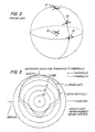
- FIG. 2 An example of this effect is shown in Fig. 2.
- the angle is defined by a line from the zenith Z to the antenna 10 and another line from the antenna 10 to a point 16 displaced from the zenith, the component of the E vector in the vertical direction is reduced; and where the angle is 90°--that is, where the angle is defined by a line from the zenith to the antenna 10 and another line from the antenna 10 to a point 18 on the horizon--, the vertical component of the E vector disappears entirely in the case of the patch and nearly so in the case of the turnstile, so that the radiation is no longer circularly polarized.
- a conventional patch antenna and to a lesser extent a conventional turnstile antenna mounted with its base plane horizontal to achieve hemispherical omnidirectionality does not effectively radiate or receive circularly-polarized radiation to or from a region lying in a direction 90° from the zenith.
- Fig. 2 shows, the vertical component of the E vector decreases to nearly zero in this region.
- the axial ratio deteriorates markedly, so that the conventional patch and turnstile are reduced to functioning essentially as linearly-polarized antennas.
- this loss of axial ratio can mean a significant loss in system performance.
- a signal from a navigation satellite is incident at a very low elevation angle above the horizon (80° or more of off-axis angle from the zenith) on a receiver mounted on a marine vehicle, there are likely to be significant multi-path reflections from the surface of the water.
- the receiving antenna is able to receive only a single, horizontally-polarized signal, it is likely that interference due to the multiple paths will induce severe fading of the signal, resulting in a loss of information.
- a conventional patch or turnstile antenna mounted on a boat that is moored in quiet waters or is in a yard or dry dock.
- such an antenna will be mounted with its ground plane parallel to the horizon and its mast extending in a direction normal to the plane of the horizon.
- the gain of the antenna will then be as shown in curve A of Fig. 3: namely, it will range from a typical maximum value at the zenith, shown in Fig. 3 as +5 decibels relative to isotropics (dBi), to a greatly reduced value on the horizon, shown in Fig. 3 as about -5 dBi.
- a primary factor in getting a good SNR is the noise figure of the preamplifier.
- the antenna is usually tuned to get the best noise figure for nominal preamplifier impedance. But if the antenna has a narrow band, it is hard to guarantee that its impedance will be close to the nominal value at the correct frequency.
- the Woodward et al. drooping turnstile antenna addresses some of the needs of a small, simple, semi-omni/CP antenna. Its most important characteristic is that the dipole elements are all straight lines, inclined at a 45 +/-5-degree angle to the mast of the turnstile. In addition, the characteristic impedance of the drooping dipole is a fixed number that must be accounted for in the impedance matching network. (Naturally it is variable over a certain range dictated by dipole physical dimensions, spacing with respect to the ground plane, etc., but the range of variation is small.)
- An object of the invention is to remedy the problems outlined above.
- an object of the invention is to provide a novel, inexpensive, and highly-effective antenna that has essentially constant gain over a hemisphere of solid angle so that it is semi-omnidirectional.
- Another object of the invention is to provide an antenna with excellent CP over a wide range of look angles, especially near the horizon.
- Another object of the invention is to provide an antenna that is sensitive over a wide bandwidth and has an excellent impedance match and VSWR.
- Another object of the invention is to provide an antenna that requires no tuning or is easily tunable without the aid of special circuit elements such as impedance-matching transformers, which are unavoidably lossy.
- an antenna comprising: base plate means forming a ground plane; mast means connected to the base plate means and extending along an axis that is normal to the ground plane; and a pair of dipole elements each having a first end connected to and supported by the mast means at a first location spaced apart from the ground plane by a predetermined distance and a second end closer to the ground plane; each of the dipole elements exhibiting a curvature in a plane containing the mast means.
- an antenna comprising: base plate means forming a ground plane XY defined by axes X and Y that intersect each other at right angles at an origin; mast means connected to the base plate means and extending along an axis Z that is normal to the ground plane at the origin; and a pair of dipole elements extending in a plane XZ defined by the axes X and Z; each of the dipole elements having a first end connected to and supported by the mast means at a first location spaced apart from the ground plane by a predetermined distance and a second end closer to the ground plane; each of the dipole elements exhibiting a curvature in the XZ plane; and the curvature having a first derivative that is continuous and has a constant sign.
- an antenna comprising: base plate means forming a ground plane; mast means connected to the base plate means and extending along an axis that is normal to the ground plane; and two pairs of orthogonally-related dipole elements connected to and supported by the mast means; wherein the mast means is formed as a coaxial cable feed.
- Fig. 1A is a perspective view of a conventional planar turnstile antenna
- Fig. 1B is a plan view of a conventional patch antenna illustrating a shape that is nearly but not quite square (L1 > L2) and a coaxial input located on a diagonal of the patch offset from the center thereof;
- Fig. 1C is a side view of the structure of Fig.1B;
- Fig. 1D is a plan view illustrating the connection of the patch of Figs. 1B and 1C to a branch line hybrid in a microstrip;
- Fig. 2 is a perspective view of a turnstile antenna illustrating its ability to transmit and receive electromagnetic radiation that is circularly polarized as a function of the angle formed by a first line extending from the zenith to the antenna and a second line extending through the antenna in a direction parallel to the direction of propagation of the electromagnetic radiation;
- Fig. 3 is a diagrammatic view in elevation showing the antenna gain in dBi as a function of the direction of propagation relative to the horizon (or zenith) in the case of a typical conventional turnstile antenna (curve A) and in the case of an antenna constructed in accordance with the invention (curve B);
- Fig. 4 is a diagram showing different curvatures in accordance with the invention of a dipole element with n as a parameter in the equation which equation represents a subset of all possible curves in accordance with the invention;
- Fig. 5 is a top plan view of a base plate that defines a ground plane in an antenna constructed in accordance with the invention
- Fig. 6 is a top plan view of a printed circuit board that supports two pairs of dipole elements and is used in constructing an antenna in accordance with the invention
- Fig. 7 is an exploded perspective view showing the assembly of the structures of Figs. 5 and 6 together with a coaxial cable that serves as a mast in order to form an antenna in accordance with the invention;
- Fig. 8 is a perspective view of an assembled antenna in accordance with the invention.
- Fig. 9 is a perspective view of the antenna of Fig. 8 with the addition of passive dipole elements forming parasitic-coupled resonators in accordance with the invention.
- Fig. 10 is a view corresponding to Fig. 8 but showing the replacement of the quarter-wave dipole elements of Fig. 8 with half-wave dipole elements connected to the ground plane;
- Fig. 11 is a graph of the return loss in VSWR as a function of frequency in the case of a conventional patch antenna.
- Fig. 12 is a graph of the return loss in VSWR as a function of frequency in the case of an antenna constructed in accordance with the invention.
- Fig. 8 shows a preferred embodiment of an antenna constructed in accordance with the invention. It comprises a base plate 20 forming a ground plane, a mast 22 connected to the base plate 20 and extending along an axis that is normal to the ground plane, and a pair of dipole elements 24 and 26 (the latter hidden in Fig. 8 but visible for example in Fig. 6) together forming a first dipole and each having a first end 28 or 30 connected to and supported by the mast 22 at a first location spaced apart from the ground plane by a predetermined distance (equal to the height of the mast 22) and a second end 32 or 34 closer to the ground plane (i.e., touching the ground plane (Fig. 10) or spaced apart from the ground plane (Fig. 8) by a distance less than the predetermined distance).
- a predetermined distance equal to the height of the mast 22
- each of the dipole elements 24 and 26 exhibits a curvature in a plane containing the mast 22.
- an additional pair of dipole elements 24' and 26' is employed, and the dipole elements of the additional pair are curved as described above.
- the mast 22 lies along the intersection of the planes defined by the curved dipole elements 24, 26 and 24', 26'.
- Convexity and concavity are defined with reference to the perspective for example of Fig. 8, which shows the antenna as it might appear when held in the hand.
- the invention preferably further comprises a pair of elongate parasitic elements 36 and 38 respectively cooperating with the pairs of dipoles 24, 26 and 24', 26' and each exhibiting a curvature in a plane containing the mast 22.
- the parasitic elements 36 and 38 may lie respectively in the planes of the dipole elements 24, 26 and 24', 26' or may be rotated about the axis defined by the mast 20 so as to lie in different planes from the planes of the dipole elements 24, 26 and 24' and 26'.
- the parasitic elements 36 and 38 may but need not be respectively generally parallel to the dipole elements 24, 26 and 24', 26'.
- the base plate 20 forms a ground plane XY (Fig. 5) defined by axes X and Y that intersect each other at right angles at an origin 0.
- the mast 22 is connected to the base plate 20 at the origin 0 and extends along an axis Z (Fig. 7) that is normal to the ground plane XY at the origin 0.
- the dipole elements 24, 26 extend in a plane XZ defined by the axes X and Z.
- the dipole elements 24', 26' extend in a plane YZ defined by the axes Y and Z.
- Each of the dipole elements 24, 26 and 24', 26' exhibits a curvature in the XZ plane or YZ plane. This curvature has a first derivative that is continuous and has a constant sign.
- the curvature is given by where x is distance from the origin 0 along the X axis, z is distance from the origin 0 along the Z axis, a and b are arbitrary constants, and n is a parameter such that 0 ⁇ n ⁇ ⁇ and n ⁇ 1.
- the curvature is given by where y is the distance from the origin 0 along the Y axis and the other symbols have the same meanings as those set out above.
- the mast 22 is formed by a coaxial cable feed.
- the center conductor of the coaxial cable feed for example the conductor 40
- the other conductor of the coaxial cable feed for example the outer conductor 42
- the ratio of dipole lengths D1/D2 is approximately equal to 1.17. The dipole lengths are different in order to provide circularly polarized waves with a single feed.
- the dipole elements 24, 26 and 24', 26' are preferably formed as part of a printed circuit board.
- a fiberglass board 44 (Fig. 6) 0.01 inches in thickness and shaped as a cross has the dipole elements 24, 26 and 24', 26' formed thereon. Adjacent orthogonal dipole elements are printed on opposite sides of the thin cross. This facilitates making connections to the coax/mast.
- the dipole elements may but need not terminate short of conductive tabs 46, 48, 50 and 52 of the same width as the crossed arms of the fiberglass board 44.
- the tabs 46, 48, 50 and 52 are formed with projections 54, 56, 58 and 60, that can be inserted respectively through holes 62, 64, 66, 68 formed in the base plate 20 (Fig. 5).
- the holes 62, 64, 66, 68 are spaced from a center hole 70 for the mast 22 by a distance which is selected relative to the lengths of the arms of the fiberglass board 44 and the height of the mast 22 so that, when the projections 54, 56, 58, 60 are inserted through the holes 62, 64, 66, 68 and the mast 22 is properly positioned, the arms of the fiberglass board 44 and therefore the dipole elements 24, 26 and 24', 26' are automatically given the desired curvature.
- Fig. 7 is an exploded view shoving the mast 22, the fiberglass board 44, and the base plate 20 in a position about to be assembled, and Fig. 8 shows the final assembly.
- Fig. 9 shows the addition of the parasitic resonators 36 and 38, which modify and in general enhance the curve B shown in Fig. 3.
- curve B shows, the antenna gain is about +3 dBi at the zenith and about -2 dBi at the horizon. While some gain is sacrificed at the zenith as compared to curve A of a conventional antenna, this is of no consequence, since at the zenith the incoming signal from a navigation satellite, for example, experiences the least attenuation and distortion.
- antenna gain is considerably improved relative to the gain of the conventional turnstile.
- signal gain remains nearly the same even at angles somewhat below the horizon.
- the direction of the curve alters both the impedance and the radiation pattern.
- the best arrangement for obtaining good impedance matching, excellent gain pattern and excellent circular polarization (axial ratio) is achieved when the dipole elements are curved in a manner resembling the spokes of an umbrella.
- the preferred embodiment of the invention may therefore be described as an "umbrella" antenna. Since the curve of each dipole element is within a plane containing the coaxial mast, there is no spiral component, which would make the shape of the dipole element three-dimensional. In the equations set out above and in Fig.
- n 1
- the curve begins to look more like a rectangle.
- the mast to which the dipole elements are attached can touch and penetrate the base plate in order to provide the support needed and provide a connection from the mast/coax to the rest of the transmitter/receiver (not shown).
- the curvature of the dipole elements in such a manner as to have a continuous first derivative with a constant sign affords two advantages previously unavailable to the designer.
- the first is that the characteristic impedance of the dipole and therefore of the entire assembly can be made to cover a very wide range.
- the second is that the radiation pattern of the dipole and therefore of the entire assembly, when used as an array to form an antenna of practical value, changes considerably because of the varying spatial relation of the dipole to the ground plane.
- the antenna can be connected to a transmitter, a receiver, or both. When connected to both, it is through a combining junction.
- the receiver it is important to be able to achieve the exact impedance match necessary to get the best overall receiver performance as determined by a system figure of merit, normally given by the ratio of antenna gain G to system noise temperature T or G/T. It can be shown that the detected SNR is directly proportional to this commonly-employed figure of merit.
- various impedance-matching techniques are employed, using various types of transmission lines or transformers. These impedance-matching circuit elements often introduce resistive losses that decrease the effective gain G of the antenna. So it is significant that the impedance level of the antenna of the invention can be varied over a wide range.
- the preferred embodiment of the invention achieves a desirable impedance level and maintains it over a wide frequency range.
- the antenna impedance be matched to the source impedance for maximum power transfer. So regardless of use, the ability to vary the impedance levels is a major advantage not easily obtainable with comparable turnstile configurations.
- the resultant characteristic impedance is brought into a region where it is optimum for achieving the best noise figure from the receiver amplifier, and therefore the best receiver figure of merit G/T.
- the tuning and impedance matching can be accomplished without use of lossy transformers or additional circuit elements.
- the shape of the dipole elements moreover makes it relatively easy to fabricate a usable antenna.
- the mast or support structure for the dipole elements is made up of the coaxial feed line, a semi-rigid outer tubing commonly used in the communications industry and having a standard 0.141-inch diameter.
- the mast actually functions as a balun, or balanced-to-unbalanced transformer, which is needed in order properly to convey energy to or from the dipole elements. It is approximately a quarter-wavelength (open-circuit case) or a half-wavelength (short-circuit case) in height above the ground plane and thereby performs the balanced-to-unbalanced conversion process.
- Circular polarization is obtained with the umbrella antenna by the method described in the Woodward et al. patent.
- the dipole elements in the XZ (or YZ) plane are made to be slightly shorter than they would be if they were truly resonant at the desired operating frequency.
- the dipole elements in the YZ (or XZ) plane are made to be slightly longer. This separation of resonant frequencies provides the mechanism for obtaining the 90-degree phase shift needed to form a circularly-polarized signal.
- the phase of the longer dipole leads the phase of the shorter dipole.
- the desired 90-degree shift can be obtained. This method is well known and is used extensively in patch and other antenna designs.
- dipole conductive elements forming two orthogonal dipole pairs.
- One adjacent pair is printed on the top side of the dielectric cross and the other is printed on the bottom side (Fig. 6).
- the inner end (i.e., the end near the mast) of a dipole element of one dipole pair is connected to the inner end of a dipole element of the other pair on the top side of the support dielectric, and the two elements thus connected are connected to, say, the center conductor of the coax forming the support mast.
- the inner ends of the two remaining dipole elements on the bottom side of the support dielectric are connected to each other and to the other (outer) conductor of the coax forming the mast.
- the type of dipole used for the radiating element can be either open-circuited, as in the preferred embodiment as shown in Figs. 6-9 of the drawing, or short-circuited, as shown in Fig. 10.
- the end not connected to the mast-balun is connected to ground electrically. In this case, it is preferably about a half-wavelength long instead of a quarter-wavelength for the open-circuited case.
- Parasitic resonators are used in the so-called Yagi antennas (for reception of television signals) to provide a change of pattern from that of the basic dipole. These parasitic resonators often have the same general shape and nearly the same size as the active dipole. In a similar manner, it is possible to alter the far-field pattern of the basic antenna in accordance with the invention having two pairs of dipoles by providing a set of parasitic resonators whose general shape mimics that of the active elements. These parasitic resonators can be arranged either to enhance the gain on-axis, at the local zenith, or to "squash" the pattern and provide an increase in gain in the plane of the horizon, at the expense of gain in the zenith direction. Further, these parasitic elements can be aligned in any azimuthal direction in the XY plane.
- each dipole need not be of the same length. There may be some applications where, say, the left half should be longer or shorter than the right half or should depart from mirror-image symmetry in some other way.
- a typical planar patch might exhibit a voltage standing wave ratio (VSWR) vs. frequency plot as shown in Fig. 11, for an antenna operating at a frequency of 1575 MHz.
- the umbrella antenna exhibits a VSWR vs. frequency plot as shown in Fig. 12.
- the acceptable VSWR limit is arbitrarily chosen to be 1.92, or a return loss of 10 dB.
- the bandwidth improvement, delimited by points 1 and 2 in each graph, is over 400 percent. This is typical of what can be expected from this new class of dipole element. Because of the new degree of freedom the curved dipole element provides, it is much easier to obtain satisfactory performance.
- VSWR vs. bandwidth is very important from the manufacturability standpoint. It means that less effort in the tuneup procedure is needed to obtain a satisfactory level of performance, and therefore the manufacturing cost can be less than in the case of a planar patch. This is a benefit to manufacturers and consumers.
- a novel and highly-effective antenna that has nearly constant gain over a hemisphere of solid angle so that it is essentially omnidirectional and circularly polarized, that is sensitive over a wide bandwidth, and that has an improved impedance match and VSWR.
- terms such as "normal,” “orthogonal,” “right angles,” and “parallel” relating one structure to another or to the environment are employed. These terms are intended to mean “generally,” “roughly,” or “substantially” normal, orthogonal, etc., and to allow for any degree of tolerance that does not prelude the substantial attainment of the objects and benefits of the invention. Many modifications of the preferred embodiments of the invention disclosed herein will readily occur to those skilled in the art, and the invention is limited only by the appended claims.
Landscapes
- Variable-Direction Aerials And Aerial Arrays (AREA)
- Details Of Aerials (AREA)
- Aerials With Secondary Devices (AREA)
Applications Claiming Priority (2)
| Application Number | Priority Date | Filing Date | Title |
|---|---|---|---|
| US44575489A | 1989-12-04 | 1989-12-04 | |
| US445754 | 1989-12-04 |
Publications (3)
| Publication Number | Publication Date |
|---|---|
| EP0431764A2 true EP0431764A2 (de) | 1991-06-12 |
| EP0431764A3 EP0431764A3 (en) | 1991-11-13 |
| EP0431764B1 EP0431764B1 (de) | 1997-03-19 |
Family
ID=23770079
Family Applications (1)
| Application Number | Title | Priority Date | Filing Date |
|---|---|---|---|
| EP90312325A Expired - Lifetime EP0431764B1 (de) | 1989-12-04 | 1990-11-12 | Antenne mit gekrümmten Dipolelementen |
Country Status (6)
| Country | Link |
|---|---|
| EP (1) | EP0431764B1 (de) |
| JP (1) | JP3045767B2 (de) |
| KR (1) | KR910013614A (de) |
| AT (1) | ATE150588T1 (de) |
| CA (1) | CA2026148C (de) |
| DE (1) | DE69030240D1 (de) |
Cited By (9)
| Publication number | Priority date | Publication date | Assignee | Title |
|---|---|---|---|---|
| WO1999062139A1 (de) * | 1998-05-27 | 1999-12-02 | Kathrein Werke Kg | Dual polarisierte mehrbereichsantenne |
| US6819300B2 (en) | 2000-03-16 | 2004-11-16 | Kathrein-Werke Kg | Dual-polarized dipole array antenna |
| US6831615B2 (en) | 2000-12-21 | 2004-12-14 | Kathrein-Werke Kg | Multi-band antenna with dielectric body improving higher frequency performance |
| US6985123B2 (en) | 2001-10-11 | 2006-01-10 | Kathrein-Werke Kg | Dual-polarization antenna array |
| US7123208B2 (en) | 1999-09-20 | 2006-10-17 | Fractus, S.A. | Multilevel antennae |
| WO2008102406A3 (en) * | 2007-02-21 | 2008-10-23 | Clarbruno Vedruccio | Circular polarization omnidirectional antenna |
| WO2014089307A1 (en) * | 2012-12-05 | 2014-06-12 | Qualcomm Incorporated | Compact dual polarization antenna |
| EP3713015A1 (de) * | 2019-03-19 | 2020-09-23 | Wilson Electronics, LLC | Antenne mit parasitären elementen |
| CN114256606A (zh) * | 2021-12-21 | 2022-03-29 | 上海海积信息科技股份有限公司 | 一种天线 |
Families Citing this family (6)
| Publication number | Priority date | Publication date | Assignee | Title |
|---|---|---|---|---|
| JP2675973B2 (ja) * | 1994-03-14 | 1997-11-12 | 八木アンテナ株式会社 | 室内アンテナ |
| WO2000069022A1 (fr) * | 1999-05-07 | 2000-11-16 | Furuno Electric Co., Ltd. | Antenne a polarisation circulaire |
| NZ504042A (en) * | 2000-04-14 | 2002-12-20 | Gregory Daniel Hall | A wide-band high-gain plate dipole antenna using a pair of plate elements arranged in the same plane |
| JP5024826B2 (ja) * | 2006-08-24 | 2012-09-12 | 株式会社日立国際電気 | アンテナ装置 |
| WO2008023800A1 (fr) | 2006-08-24 | 2008-02-28 | Hitachi Kokusai Electric Inc. | Dispositif d'antenne |
| US9548526B2 (en) * | 2012-12-21 | 2017-01-17 | Htc Corporation | Small-size antenna system with adjustable polarization |
Family Cites Families (2)
| Publication number | Priority date | Publication date | Assignee | Title |
|---|---|---|---|---|
| US3811127A (en) * | 1972-08-10 | 1974-05-14 | Collins Radio Co | Antenna for airborne satellite communications |
| US4878062A (en) * | 1988-07-28 | 1989-10-31 | Dayton-Granger, Inc. | Global position satellite antenna |
-
1990
- 1990-09-25 CA CA002026148A patent/CA2026148C/en not_active Expired - Fee Related
- 1990-10-12 KR KR1019900016183A patent/KR910013614A/ko not_active Withdrawn
- 1990-11-12 AT AT90312325T patent/ATE150588T1/de active
- 1990-11-12 EP EP90312325A patent/EP0431764B1/de not_active Expired - Lifetime
- 1990-11-12 DE DE69030240T patent/DE69030240D1/de not_active Expired - Lifetime
- 1990-11-30 JP JP2337042A patent/JP3045767B2/ja not_active Expired - Lifetime
Cited By (17)
| Publication number | Priority date | Publication date | Assignee | Title |
|---|---|---|---|---|
| US6333720B1 (en) | 1998-05-27 | 2001-12-25 | Kathrein-Werke Ag | Dual polarized multi-range antenna |
| AU755335B2 (en) * | 1998-05-27 | 2002-12-12 | Kathrein-Werke Kg | Dual polarised multi-range antenna |
| WO1999062139A1 (de) * | 1998-05-27 | 1999-12-02 | Kathrein Werke Kg | Dual polarisierte mehrbereichsantenne |
| US7505007B2 (en) | 1999-09-20 | 2009-03-17 | Fractus, S.A. | Multi-level antennae |
| US10056682B2 (en) | 1999-09-20 | 2018-08-21 | Fractus, S.A. | Multilevel antennae |
| US7123208B2 (en) | 1999-09-20 | 2006-10-17 | Fractus, S.A. | Multilevel antennae |
| US7394432B2 (en) | 1999-09-20 | 2008-07-01 | Fractus, S.A. | Multilevel antenna |
| US7397431B2 (en) | 1999-09-20 | 2008-07-08 | Fractus, S.A. | Multilevel antennae |
| US9761934B2 (en) | 1999-09-20 | 2017-09-12 | Fractus, S.A. | Multilevel antennae |
| US6819300B2 (en) | 2000-03-16 | 2004-11-16 | Kathrein-Werke Kg | Dual-polarized dipole array antenna |
| US6831615B2 (en) | 2000-12-21 | 2004-12-14 | Kathrein-Werke Kg | Multi-band antenna with dielectric body improving higher frequency performance |
| US6985123B2 (en) | 2001-10-11 | 2006-01-10 | Kathrein-Werke Kg | Dual-polarization antenna array |
| WO2008102406A3 (en) * | 2007-02-21 | 2008-10-23 | Clarbruno Vedruccio | Circular polarization omnidirectional antenna |
| WO2014089307A1 (en) * | 2012-12-05 | 2014-06-12 | Qualcomm Incorporated | Compact dual polarization antenna |
| US9099781B2 (en) | 2012-12-05 | 2015-08-04 | Qualcomm Incorporated | Compact dual polarization antenna |
| EP3713015A1 (de) * | 2019-03-19 | 2020-09-23 | Wilson Electronics, LLC | Antenne mit parasitären elementen |
| CN114256606A (zh) * | 2021-12-21 | 2022-03-29 | 上海海积信息科技股份有限公司 | 一种天线 |
Also Published As
| Publication number | Publication date |
|---|---|
| JPH03231503A (ja) | 1991-10-15 |
| ATE150588T1 (de) | 1997-04-15 |
| CA2026148C (en) | 2001-01-16 |
| CA2026148A1 (en) | 1991-06-05 |
| EP0431764B1 (de) | 1997-03-19 |
| JP3045767B2 (ja) | 2000-05-29 |
| EP0431764A3 (en) | 1991-11-13 |
| KR910013614A (ko) | 1991-08-08 |
| DE69030240D1 (de) | 1997-04-24 |
Similar Documents
| Publication | Publication Date | Title |
|---|---|---|
| US5173715A (en) | Antenna with curved dipole elements | |
| US5467095A (en) | Low profile antenna | |
| US5608413A (en) | Frequency-selective antenna with different signal polarizations | |
| US5450093A (en) | Center-fed multifilar helix antenna | |
| US5790080A (en) | Meander line loaded antenna | |
| US7369095B2 (en) | Source-antennas for transmitting/receiving electromagnetic waves | |
| US6246377B1 (en) | Antenna comprising two separate wideband notch regions on one coplanar substrate | |
| AU618804B2 (en) | Monopole/l-shaped parasitic elements for circularly/ eliptically polarized wave transceiving | |
| US6057802A (en) | Trimmed foursquare antenna radiating element | |
| US6133891A (en) | Quadrifilar helix antenna | |
| CA2343729C (en) | Circularly polarized dielectric resonator antenna | |
| CN100420094C (zh) | 嵌套的回转式天线 | |
| US6292153B1 (en) | Antenna comprising two wideband notch regions on one coplanar substrate | |
| US6008773A (en) | Reflector-provided dipole antenna | |
| EP1782499B1 (de) | System und verfahren für eine omnidirektionale planarantennenvorrichtung mit wählbaren elementen | |
| EP0431764B1 (de) | Antenne mit gekrümmten Dipolelementen | |
| US8487821B2 (en) | Methods and apparatus for a low reflectivity compensated antenna | |
| US20040032378A1 (en) | Broadband starfish antenna and array thereof | |
| EP3716405B1 (de) | Linear-zu-cp-polarisator mit verbesserter leistung in victs-antennen | |
| US6064348A (en) | Method and apparatus for a dual frequency band antenna | |
| WO1997025755A1 (en) | Slot spiral antenna with integrated balun and feed | |
| US5764195A (en) | UHF/VHF multifunction ocean antenna system | |
| US11502414B2 (en) | Microstrip patch antenna system having adjustable radiation pattern shapes and related method | |
| CN110544819A (zh) | 一种宽带圆极化交叉磁电偶极子天线 | |
| EP1033782B1 (de) | Monopolantenne |
Legal Events
| Date | Code | Title | Description |
|---|---|---|---|
| PUAI | Public reference made under article 153(3) epc to a published international application that has entered the european phase |
Free format text: ORIGINAL CODE: 0009012 |
|
| AK | Designated contracting states |
Kind code of ref document: A2 Designated state(s): AT BE CH DE DK ES FR GB GR IT LI LU NL SE |
|
| PUAL | Search report despatched |
Free format text: ORIGINAL CODE: 0009013 |
|
| AK | Designated contracting states |
Kind code of ref document: A3 Designated state(s): AT BE CH DE DK ES FR GB GR IT LI LU NL SE |
|
| 17P | Request for examination filed |
Effective date: 19920710 |
|
| 17Q | First examination report despatched |
Effective date: 19940421 |
|
| GRAG | Despatch of communication of intention to grant |
Free format text: ORIGINAL CODE: EPIDOS AGRA |
|
| GRAH | Despatch of communication of intention to grant a patent |
Free format text: ORIGINAL CODE: EPIDOS IGRA |
|
| GRAH | Despatch of communication of intention to grant a patent |
Free format text: ORIGINAL CODE: EPIDOS IGRA |
|
| GRAA | (expected) grant |
Free format text: ORIGINAL CODE: 0009210 |
|
| AK | Designated contracting states |
Kind code of ref document: B1 Designated state(s): AT BE CH DE DK ES FR GB GR IT LI LU NL SE |
|
| PG25 | Lapsed in a contracting state [announced via postgrant information from national office to epo] |
Ref country code: FR Effective date: 19970319 Ref country code: IT Free format text: LAPSE BECAUSE OF FAILURE TO SUBMIT A TRANSLATION OF THE DESCRIPTION OR TO PAY THE FEE WITHIN THE PRESCRIBED TIME-LIMIT;WARNING: LAPSES OF ITALIAN PATENTS WITH EFFECTIVE DATE BEFORE 2007 MAY HAVE OCCURRED AT ANY TIME BEFORE 2007. THE CORRECT EFFECTIVE DATE MAY BE DIFFERENT FROM THE ONE RECORDED. Effective date: 19970319 Ref country code: LI Effective date: 19970319 Ref country code: ES Free format text: THE PATENT HAS BEEN ANNULLED BY A DECISION OF A NATIONAL AUTHORITY Effective date: 19970319 Ref country code: GR Free format text: LAPSE BECAUSE OF FAILURE TO SUBMIT A TRANSLATION OF THE DESCRIPTION OR TO PAY THE FEE WITHIN THE PRESCRIBED TIME-LIMIT Effective date: 19970319 Ref country code: BE Effective date: 19970319 Ref country code: DK Effective date: 19970319 Ref country code: NL Free format text: LAPSE BECAUSE OF FAILURE TO SUBMIT A TRANSLATION OF THE DESCRIPTION OR TO PAY THE FEE WITHIN THE PRESCRIBED TIME-LIMIT Effective date: 19970319 Ref country code: AT Effective date: 19970319 Ref country code: CH Effective date: 19970319 |
|
| REF | Corresponds to: |
Ref document number: 150588 Country of ref document: AT Date of ref document: 19970415 Kind code of ref document: T |
|
| REG | Reference to a national code |
Ref country code: CH Ref legal event code: EP |
|
| REF | Corresponds to: |
Ref document number: 69030240 Country of ref document: DE Date of ref document: 19970424 |
|
| PG25 | Lapsed in a contracting state [announced via postgrant information from national office to epo] |
Ref country code: SE Effective date: 19970619 |
|
| PG25 | Lapsed in a contracting state [announced via postgrant information from national office to epo] |
Ref country code: DE Effective date: 19970620 |
|
| NLV1 | Nl: lapsed or annulled due to failure to fulfill the requirements of art. 29p and 29m of the patents act | ||
| EN | Fr: translation not filed | ||
| REG | Reference to a national code |
Ref country code: CH Ref legal event code: PL |
|
| PG25 | Lapsed in a contracting state [announced via postgrant information from national office to epo] |
Ref country code: LU Free format text: LAPSE BECAUSE OF NON-PAYMENT OF DUE FEES Effective date: 19971112 |
|
| PLBE | No opposition filed within time limit |
Free format text: ORIGINAL CODE: 0009261 |
|
| STAA | Information on the status of an ep patent application or granted ep patent |
Free format text: STATUS: NO OPPOSITION FILED WITHIN TIME LIMIT |
|
| 26N | No opposition filed | ||
| PGFP | Annual fee paid to national office [announced via postgrant information from national office to epo] |
Ref country code: GB Payment date: 20011018 Year of fee payment: 12 |
|
| REG | Reference to a national code |
Ref country code: GB Ref legal event code: IF02 |
|
| PG25 | Lapsed in a contracting state [announced via postgrant information from national office to epo] |
Ref country code: GB Free format text: LAPSE BECAUSE OF NON-PAYMENT OF DUE FEES Effective date: 20021112 |
|
| GBPC | Gb: european patent ceased through non-payment of renewal fee |