EP0431812A2 - Circuit de protection pour tube lumineux - Google Patents
Circuit de protection pour tube lumineux Download PDFInfo
- Publication number
- EP0431812A2 EP0431812A2 EP90312830A EP90312830A EP0431812A2 EP 0431812 A2 EP0431812 A2 EP 0431812A2 EP 90312830 A EP90312830 A EP 90312830A EP 90312830 A EP90312830 A EP 90312830A EP 0431812 A2 EP0431812 A2 EP 0431812A2
- Authority
- EP
- European Patent Office
- Prior art keywords
- circuit
- transformer
- power supply
- luminous tube
- signal
- Prior art date
- Legal status (The legal status is an assumption and is not a legal conclusion. Google has not performed a legal analysis and makes no representation as to the accuracy of the status listed.)
- Granted
Links
Images






Classifications
-
- H—ELECTRICITY
- H05—ELECTRIC TECHNIQUES NOT OTHERWISE PROVIDED FOR
- H05B—ELECTRIC HEATING; ELECTRIC LIGHT SOURCES NOT OTHERWISE PROVIDED FOR; CIRCUIT ARRANGEMENTS FOR ELECTRIC LIGHT SOURCES, IN GENERAL
- H05B41/00—Circuit arrangements or apparatus for igniting or operating discharge lamps
- H05B41/14—Circuit arrangements
- H05B41/26—Circuit arrangements in which the lamp is fed by power derived from DC by means of a converter, e.g. by high-voltage DC
- H05B41/28—Circuit arrangements in which the lamp is fed by power derived from DC by means of a converter, e.g. by high-voltage DC using static converters
- H05B41/282—Circuit arrangements in which the lamp is fed by power derived from DC by means of a converter, e.g. by high-voltage DC using static converters with semiconductor devices
- H05B41/285—Arrangements for protecting lamps or circuits against abnormal operating conditions
- H05B41/2851—Arrangements for protecting lamps or circuits against abnormal operating conditions for protecting the circuit against abnormal operating conditions
- H05B41/2856—Arrangements for protecting lamps or circuits against abnormal operating conditions for protecting the circuit against abnormal operating conditions against internal abnormal circuit conditions
-
- H—ELECTRICITY
- H02—GENERATION; CONVERSION OR DISTRIBUTION OF ELECTRIC POWER
- H02H—EMERGENCY PROTECTIVE CIRCUIT ARRANGEMENTS
- H02H3/00—Emergency protective circuit arrangements for automatic disconnection directly responsive to an undesired change from normal electric working condition with or without subsequent reconnection ; integrated protection
- H02H3/02—Details
- H02H3/06—Details with automatic reconnection
- H02H3/07—Details with automatic reconnection and with permanent disconnection after a predetermined number of reconnection cycles
-
- H—ELECTRICITY
- H02—GENERATION; CONVERSION OR DISTRIBUTION OF ELECTRIC POWER
- H02H—EMERGENCY PROTECTIVE CIRCUIT ARRANGEMENTS
- H02H5/00—Emergency protective circuit arrangements for automatic disconnection directly responsive to an undesired change from normal non-electric working conditions with or without subsequent reconnection
- H02H5/04—Emergency protective circuit arrangements for automatic disconnection directly responsive to an undesired change from normal non-electric working conditions with or without subsequent reconnection responsive to abnormal temperature
-
- H—ELECTRICITY
- H02—GENERATION; CONVERSION OR DISTRIBUTION OF ELECTRIC POWER
- H02H—EMERGENCY PROTECTIVE CIRCUIT ARRANGEMENTS
- H02H7/00—Emergency protective circuit arrangements specially adapted for specific types of electric machines or apparatus or for sectionalised protection of cable or line systems, and effecting automatic switching in the event of an undesired change from normal working conditions
-
- H—ELECTRICITY
- H05—ELECTRIC TECHNIQUES NOT OTHERWISE PROVIDED FOR
- H05B—ELECTRIC HEATING; ELECTRIC LIGHT SOURCES NOT OTHERWISE PROVIDED FOR; CIRCUIT ARRANGEMENTS FOR ELECTRIC LIGHT SOURCES, IN GENERAL
- H05B41/00—Circuit arrangements or apparatus for igniting or operating discharge lamps
- H05B41/14—Circuit arrangements
- H05B41/26—Circuit arrangements in which the lamp is fed by power derived from DC by means of a converter, e.g. by high-voltage DC
- H05B41/28—Circuit arrangements in which the lamp is fed by power derived from DC by means of a converter, e.g. by high-voltage DC using static converters
- H05B41/282—Circuit arrangements in which the lamp is fed by power derived from DC by means of a converter, e.g. by high-voltage DC using static converters with semiconductor devices
- H05B41/285—Arrangements for protecting lamps or circuits against abnormal operating conditions
- H05B41/2851—Arrangements for protecting lamps or circuits against abnormal operating conditions for protecting the circuit against abnormal operating conditions
-
- H—ELECTRICITY
- H05—ELECTRIC TECHNIQUES NOT OTHERWISE PROVIDED FOR
- H05B—ELECTRIC HEATING; ELECTRIC LIGHT SOURCES NOT OTHERWISE PROVIDED FOR; CIRCUIT ARRANGEMENTS FOR ELECTRIC LIGHT SOURCES, IN GENERAL
- H05B41/00—Circuit arrangements or apparatus for igniting or operating discharge lamps
- H05B41/14—Circuit arrangements
- H05B41/26—Circuit arrangements in which the lamp is fed by power derived from DC by means of a converter, e.g. by high-voltage DC
- H05B41/28—Circuit arrangements in which the lamp is fed by power derived from DC by means of a converter, e.g. by high-voltage DC using static converters
- H05B41/282—Circuit arrangements in which the lamp is fed by power derived from DC by means of a converter, e.g. by high-voltage DC using static converters with semiconductor devices
- H05B41/285—Arrangements for protecting lamps or circuits against abnormal operating conditions
- H05B41/2851—Arrangements for protecting lamps or circuits against abnormal operating conditions for protecting the circuit against abnormal operating conditions
- H05B41/2855—Arrangements for protecting lamps or circuits against abnormal operating conditions for protecting the circuit against abnormal operating conditions against abnormal lamp operating conditions
-
- H—ELECTRICITY
- H05—ELECTRIC TECHNIQUES NOT OTHERWISE PROVIDED FOR
- H05B—ELECTRIC HEATING; ELECTRIC LIGHT SOURCES NOT OTHERWISE PROVIDED FOR; CIRCUIT ARRANGEMENTS FOR ELECTRIC LIGHT SOURCES, IN GENERAL
- H05B41/00—Circuit arrangements or apparatus for igniting or operating discharge lamps
- H05B41/14—Circuit arrangements
- H05B41/36—Controlling
Definitions
- luminous tube transformers incorporate a magnetic shunt around part of the core that limits the output current to 120 milliamps or lower, the potential for arcing is still present.
- the present invention provides a method of determining critical changes within these parameters and the means to protect the circuit when they occur.
- a threshold adjusting potentiometer 28 determines the signal level that is then amplified and applied to the modified window comparator circuit in 26.
- the window comparator circuit provides a high fault signal or a low fault signal if the amplified detector signal exceeds one of the window limits.
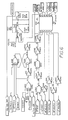
- a temperature compensation circuit 30 senses the ambient air temperature and accordingly selects an appropriate delay time for a logic circuit to recognise a fault signal from the comparator circuit, inhibits the logic circuit from generating a turn on command to a driver circuit, and also provides the function of inhibiting power to the transformer 12 in the event the ambient air temperature is above a maximum or below or a minimum.
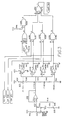
- the circuit comprised of U5A, U5B, and U6D act as a power up one shot to generate a pulse delayed approximately 1.5 seconds to allow power supply stabilisation.
- the circuit comprised of U7A, U8 and U20A is a digital type of one shot. When triggered by U5D it produces 1 second pulse outputs called INITIALISE, and INITIALISE . The function of these signals is to reset key logic functions to the initial state.
- the circuit comprised of U7B, U9 and U20B also comprise a digital one shot. The output is a 122 microsecond pulse call START . Its function is to initiate the turn on process. It is triggered by the INITIALISE signal routed through the normally closed contacts of the press to adjust switch 38. It will be inhibited if the switch is pressed or if the FHOLD 2 signal is present at U5F.
- SETTLE 1 digital one shot U10A, U11 and U20C.
- the outputs of this one shot are called SETTLE 1 and SETTLE 1 .
- Their function is to command the drive circuitry to turn on power to transformer primary 14 and to inhibit fault detection until the luminous tube gas ionisation stabilises.
- the length of SETTLE 1 is determined as follows: three output pulses of 0.2, 0.4 and 0.8 second duration are simultaneously generated by U11 and sent to the temperature compensation circuit 30, Figure 3.
- the temperature compensation circuit 30 will select one of these pulses, based on the ambient air temperature, and send it back to U20C to terminate the SETTLE 1 signal. If the ambient air temperature exceeds the upper or lower limit, the temperature compensation circuit will send a logic 1 to U20C to inhibit the SETTLE 1 pulse and thereby prevent primary power turn on.
- type D Flip-Flop U10B is set and the Q output called HOLDGATE 1 goes to logic 0. This is then applied to OR gates U21A and U21B. Also present at these gates is HFAULT and L FAULT . If the luminous tube is operating normally those signals are both at logic 1. If a fault occurs, example HFAULT, HFAULT goes low and sets R-S Latch U12A. The Q output, HFHOLD 1, generates FHOLD 1 at U21C which triggers one shot U13A, U14 and U21D to produce a 10 second signal called SIGNOFF which tells the drive circuit 36 to turn primary power off.
- SIGNOFF 10 second signal
- ACGATE U19A
- ACGATE is logic 0. This is applied to the input of U31.
- U31 is a current-sink/driver with active low inputs and open collector outputs.
- ACGATE is a logic 0, U31 output turns on applying a ground to the input of optoisolator U32, turning it on.
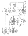
- step 124 disconnects power to the transformer 12. Also if the ambient air temperature was determined to be above the maximum or below the minimum, the circuitry is inhibited from further start up in step 126. In order to again initialise the circuitry 10 step 128 provides for manual adjustment for recalibrating and resetting the circuit 10.
Landscapes
- Protection Of Transformers (AREA)
- Protection Of Static Devices (AREA)
- Circuit Arrangements For Discharge Lamps (AREA)
- Vessels And Coating Films For Discharge Lamps (AREA)
- Tires In General (AREA)
- Measurement Of Current Or Voltage (AREA)
Applications Claiming Priority (4)
| Application Number | Priority Date | Filing Date | Title |
|---|---|---|---|
| US44182189A | 1989-11-27 | 1989-11-27 | |
| US441821 | 1989-11-27 | ||
| US58095790A | 1990-09-11 | 1990-09-11 | |
| US580957 | 1990-09-11 |
Publications (3)
| Publication Number | Publication Date |
|---|---|
| EP0431812A2 true EP0431812A2 (fr) | 1991-06-12 |
| EP0431812A3 EP0431812A3 (en) | 1992-06-03 |
| EP0431812B1 EP0431812B1 (fr) | 1996-10-16 |
Family
ID=27032965
Family Applications (1)
| Application Number | Title | Priority Date | Filing Date |
|---|---|---|---|
| EP90312830A Expired - Lifetime EP0431812B1 (fr) | 1989-11-27 | 1990-11-26 | Circuit de protection pour tube lumineux |
Country Status (6)
| Country | Link |
|---|---|
| US (1) | US5621598A (fr) |
| EP (1) | EP0431812B1 (fr) |
| JP (1) | JPH03265423A (fr) |
| AT (1) | ATE144355T1 (fr) |
| CA (1) | CA2030848C (fr) |
| DE (1) | DE69028902D1 (fr) |
Cited By (1)
| Publication number | Priority date | Publication date | Assignee | Title |
|---|---|---|---|---|
| EP0828409A3 (fr) * | 1996-09-06 | 1999-05-12 | Everbrite Inc. | Appareil pour détecter des défauts de tube lumineux et d'alimentation de puissance même en l'absence de courants de défaut à la terre |
Families Citing this family (6)
| Publication number | Priority date | Publication date | Assignee | Title |
|---|---|---|---|---|
| US7377445B1 (en) | 2001-05-31 | 2008-05-27 | Alien Technology Corporation | Integrated circuits with persistent data storage |
| US6942155B1 (en) * | 2001-05-31 | 2005-09-13 | Alien Technology Corporation | Integrated circuits with persistent data storage |
| US7183721B2 (en) * | 2005-06-30 | 2007-02-27 | Osram Sylvania, Inc. | Ballast with circuit for detecting and eliminating an arc condition |
| US7955234B1 (en) | 2007-02-28 | 2011-06-07 | Pursley Michael G | Exercise device and method |
| DE102010041987A1 (de) * | 2010-10-05 | 2012-04-05 | Tridonic Gmbh & Co. Kg | Betriebsgerät mit einstellbarer kritischer Temperatur |
| CN110336247B (zh) * | 2019-08-14 | 2022-01-28 | 张晓菊 | 一种用于保护变压器的方法、容控器以及保护系统 |
Family Cites Families (10)
| Publication number | Priority date | Publication date | Assignee | Title |
|---|---|---|---|---|
| DE1033329B (de) * | 1955-05-20 | 1958-07-03 | Weiss Viktor | Schutzschaltung fuer Hochspannungsleuchtroehrenstromkreise |
| US3793559A (en) * | 1972-08-10 | 1974-02-19 | Westinghouse Electric Corp | Transformer apparatus and monitoring system |
| US3781636A (en) * | 1973-04-30 | 1973-12-25 | Honeywell Inf Systems | Lead network to prevent voltage overshoot in a switching regulator |
| US4210947A (en) * | 1977-10-06 | 1980-07-01 | Sony Corporation | Protective circuit for a switching regulator |
| US4612617A (en) * | 1983-03-02 | 1986-09-16 | Siemens-Allis, Inc. | Method and apparatus for monitoring instantaneous electrical parameters of a power distribution system |
| GB2139436B (en) * | 1983-03-17 | 1986-10-08 | Janan Emmanuel Allos | Mains protection device |
| EP0204978B1 (fr) * | 1985-05-21 | 1992-01-08 | Fujitsu Limited | Dispositif de commande pour la mise hors service d'une source d'alimentation électrique |
| US4989155A (en) * | 1986-08-14 | 1991-01-29 | Gte Valenite Corporation | Intelligent power monitor |
| US4965692A (en) * | 1989-07-31 | 1990-10-23 | Siemens Transmission Systems, Inc. | Overload detector and protection circuit |
| US5136458A (en) * | 1989-08-31 | 1992-08-04 | Square D Company | Microcomputer based electronic trip system for circuit breakers |
-
1990
- 1990-11-26 DE DE69028902T patent/DE69028902D1/de not_active Expired - Lifetime
- 1990-11-26 EP EP90312830A patent/EP0431812B1/fr not_active Expired - Lifetime
- 1990-11-26 CA CA002030848A patent/CA2030848C/fr not_active Expired - Fee Related
- 1990-11-26 AT AT90312830T patent/ATE144355T1/de not_active IP Right Cessation
- 1990-11-27 JP JP2321399A patent/JPH03265423A/ja active Pending
-
1995
- 1995-06-07 US US08/478,894 patent/US5621598A/en not_active Expired - Fee Related
Cited By (1)
| Publication number | Priority date | Publication date | Assignee | Title |
|---|---|---|---|---|
| EP0828409A3 (fr) * | 1996-09-06 | 1999-05-12 | Everbrite Inc. | Appareil pour détecter des défauts de tube lumineux et d'alimentation de puissance même en l'absence de courants de défaut à la terre |
Also Published As
| Publication number | Publication date |
|---|---|
| EP0431812B1 (fr) | 1996-10-16 |
| EP0431812A3 (en) | 1992-06-03 |
| DE69028902D1 (de) | 1996-11-21 |
| US5621598A (en) | 1997-04-15 |
| CA2030848C (fr) | 2002-06-25 |
| ATE144355T1 (de) | 1996-11-15 |
| JPH03265423A (ja) | 1991-11-26 |
| CA2030848A1 (fr) | 1991-05-28 |
Similar Documents
| Publication | Publication Date | Title |
|---|---|---|
| US6999289B2 (en) | Arc fault circuit interrupter which detects the cessation of arcs of an arc fault | |
| US4707759A (en) | Universal fault circuit interrupter | |
| EP0480937B1 (fr) | Circuit de protection contre la perte de neutre ou de mise a la terre | |
| US4228475A (en) | Ground monitoring system | |
| US6229679B1 (en) | Arc fault circuit interrupter without DC supply | |
| US5479086A (en) | Process and device for reducing the inrush current when powering aninductive load | |
| US4150411A (en) | Ground fault circuit interrupter utilizing a single transformer | |
| US4580186A (en) | Grounding and ground fault detection circuits | |
| US4363064A (en) | Overcurrent protection system | |
| US4999728A (en) | Power surge protection circuit | |
| US4027203A (en) | Protective switch device for electrical distribution systems | |
| JP3239754B2 (ja) | 限流装置 | |
| CA1225700A (fr) | Systemes de controle d'installation electrique | |
| US3944891A (en) | Circuit for verifying correct connections to a three-wire dual voltage power distribution system and the absence of open circuit conditions therein | |
| EP1021816B1 (fr) | Commutateur electronique pour une reponse rapide et automatique aux surcharges de courant | |
| EP0345679A2 (fr) | Circuit de protection contre des défauts pour alimentation de courant | |
| US3899717A (en) | Ground fault detectors | |
| EP0431812B1 (fr) | Circuit de protection pour tube lumineux | |
| EP0483164B1 (fr) | Coupe-circuit en cas de defaut a la terre | |
| US4353103A (en) | Ground fault interrupter circuit | |
| CA1194105A (fr) | Circuit de protection de transformateur de courant en circuit ouvert | |
| GB2224404A (en) | Residual current device with missing neutral protection | |
| US4034267A (en) | Indicating apparatus | |
| US4045822A (en) | Ground fault interrupter apparatus | |
| US6268988B1 (en) | Ground fault detector for gas discharge tubing |
Legal Events
| Date | Code | Title | Description |
|---|---|---|---|
| PUAI | Public reference made under article 153(3) epc to a published international application that has entered the european phase |
Free format text: ORIGINAL CODE: 0009012 |
|
| AK | Designated contracting states |
Kind code of ref document: A2 Designated state(s): AT BE CH DE DK ES FR GB GR IT LI LU NL SE |
|
| PUAL | Search report despatched |
Free format text: ORIGINAL CODE: 0009013 |
|
| AK | Designated contracting states |
Kind code of ref document: A3 Designated state(s): AT BE CH DE DK ES FR GB GR IT LI LU NL SE |
|
| 17P | Request for examination filed |
Effective date: 19921130 |
|
| 17Q | First examination report despatched |
Effective date: 19940125 |
|
| GRAG | Despatch of communication of intention to grant |
Free format text: ORIGINAL CODE: EPIDOS AGRA |
|
| GRAH | Despatch of communication of intention to grant a patent |
Free format text: ORIGINAL CODE: EPIDOS IGRA |
|
| GRAH | Despatch of communication of intention to grant a patent |
Free format text: ORIGINAL CODE: EPIDOS IGRA |
|
| GRAA | (expected) grant |
Free format text: ORIGINAL CODE: 0009210 |
|
| AK | Designated contracting states |
Kind code of ref document: B1 Designated state(s): AT BE CH DE DK ES FR GB GR IT LI LU NL SE |
|
| PG25 | Lapsed in a contracting state [announced via postgrant information from national office to epo] |
Ref country code: CH Free format text: LAPSE BECAUSE OF FAILURE TO SUBMIT A TRANSLATION OF THE DESCRIPTION OR TO PAY THE FEE WITHIN THE PRESCRIBED TIME-LIMIT Effective date: 19961016 Ref country code: LI Free format text: LAPSE BECAUSE OF FAILURE TO SUBMIT A TRANSLATION OF THE DESCRIPTION OR TO PAY THE FEE WITHIN THE PRESCRIBED TIME-LIMIT Effective date: 19961016 Ref country code: FR Effective date: 19961016 Ref country code: GR Free format text: LAPSE BECAUSE OF FAILURE TO SUBMIT A TRANSLATION OF THE DESCRIPTION OR TO PAY THE FEE WITHIN THE PRESCRIBED TIME-LIMIT Effective date: 19961016 Ref country code: DK Effective date: 19961016 Ref country code: ES Free format text: THE PATENT HAS BEEN ANNULLED BY A DECISION OF A NATIONAL AUTHORITY Effective date: 19961016 Ref country code: AT Effective date: 19961016 Ref country code: NL Free format text: LAPSE BECAUSE OF FAILURE TO SUBMIT A TRANSLATION OF THE DESCRIPTION OR TO PAY THE FEE WITHIN THE PRESCRIBED TIME-LIMIT Effective date: 19961016 Ref country code: BE Effective date: 19961016 Ref country code: IT Free format text: LAPSE BECAUSE OF FAILURE TO SUBMIT A TRANSLATION OF THE DESCRIPTION OR TO PAY THE FEE WITHIN THE PRE;WARNING: LAPSES OF ITALIAN PATENTS WITH EFFECTIVE DATE BEFORE 2007 MAY HAVE OCCURRED AT ANY TIME BEFORE 2007. THE CORRECT EFFECTIVE DATE MAY BE DIFFERENT FROM THE ONE RECORDED.SCRIBED TIME-LIMIT Effective date: 19961016 |
|
| REF | Corresponds to: |
Ref document number: 144355 Country of ref document: AT Date of ref document: 19961115 Kind code of ref document: T |
|
| REF | Corresponds to: |
Ref document number: 69028902 Country of ref document: DE Date of ref document: 19961121 |
|
| PG25 | Lapsed in a contracting state [announced via postgrant information from national office to epo] |
Ref country code: LU Free format text: LAPSE BECAUSE OF NON-PAYMENT OF DUE FEES Effective date: 19961130 |
|
| PG25 | Lapsed in a contracting state [announced via postgrant information from national office to epo] |
Ref country code: SE Effective date: 19970116 |
|
| PG25 | Lapsed in a contracting state [announced via postgrant information from national office to epo] |
Ref country code: DE Effective date: 19970117 |
|
| NLV1 | Nl: lapsed or annulled due to failure to fulfill the requirements of art. 29p and 29m of the patents act | ||
| EN | Fr: translation not filed | ||
| EN | Fr: translation not filed |
Free format text: CORRECTIONS |
|
| REG | Reference to a national code |
Ref country code: CH Ref legal event code: PL |
|
| PLBE | No opposition filed within time limit |
Free format text: ORIGINAL CODE: 0009261 |
|
| STAA | Information on the status of an ep patent application or granted ep patent |
Free format text: STATUS: NO OPPOSITION FILED WITHIN TIME LIMIT |
|
| 26N | No opposition filed | ||
| REG | Reference to a national code |
Ref country code: GB Ref legal event code: IF02 |
|
| GBPC | Gb: european patent ceased through non-payment of renewal fee |
Effective date: 20031126 |
|
| REG | Reference to a national code |
Ref country code: GB Ref legal event code: 728V |
|
| REG | Reference to a national code |
Ref country code: GB Ref legal event code: 728Y |
|
| PGFP | Annual fee paid to national office [announced via postgrant information from national office to epo] |
Ref country code: GB Payment date: 20080512 Year of fee payment: 18 |
|
| GBPC | Gb: european patent ceased through non-payment of renewal fee |
Effective date: 20081126 |
|
| PG25 | Lapsed in a contracting state [announced via postgrant information from national office to epo] |
Ref country code: GB Free format text: LAPSE BECAUSE OF NON-PAYMENT OF DUE FEES Effective date: 20081126 |