EP0431842A2 - Procédé de surveillance et capteur à fibres optiques destinés aux signaux cardio-vasculaires - Google Patents
Procédé de surveillance et capteur à fibres optiques destinés aux signaux cardio-vasculaires Download PDFInfo
- Publication number
- EP0431842A2 EP0431842A2 EP90312998A EP90312998A EP0431842A2 EP 0431842 A2 EP0431842 A2 EP 0431842A2 EP 90312998 A EP90312998 A EP 90312998A EP 90312998 A EP90312998 A EP 90312998A EP 0431842 A2 EP0431842 A2 EP 0431842A2
- Authority
- EP
- European Patent Office
- Prior art keywords
- sensor
- encapsulating material
- optical fibres
- cavity
- sounds
- Prior art date
- Legal status (The legal status is an assumption and is not a legal conclusion. Google has not performed a legal analysis and makes no representation as to the accuracy of the status listed.)
- Withdrawn
Links
Images


Classifications
-
- A—HUMAN NECESSITIES
- A61—MEDICAL OR VETERINARY SCIENCE; HYGIENE
- A61B—DIAGNOSIS; SURGERY; IDENTIFICATION
- A61B5/00—Measuring for diagnostic purposes; Identification of persons
- A61B5/02—Detecting, measuring or recording for evaluating the cardiovascular system, e.g. pulse, heart rate, blood pressure or blood flow
- A61B5/024—Measuring pulse rate or heart rate
- A61B5/02416—Measuring pulse rate or heart rate using photoplethysmograph signals, e.g. generated by infrared radiation
- A61B5/02427—Details of sensor
- A61B5/02433—Details of sensor for infrared radiation
-
- A—HUMAN NECESSITIES
- A61—MEDICAL OR VETERINARY SCIENCE; HYGIENE
- A61B—DIAGNOSIS; SURGERY; IDENTIFICATION
- A61B5/00—Measuring for diagnostic purposes; Identification of persons
- A61B5/02—Detecting, measuring or recording for evaluating the cardiovascular system, e.g. pulse, heart rate, blood pressure or blood flow
- A61B5/024—Measuring pulse rate or heart rate
- A61B5/02416—Measuring pulse rate or heart rate using photoplethysmograph signals, e.g. generated by infrared radiation
-
- A—HUMAN NECESSITIES
- A61—MEDICAL OR VETERINARY SCIENCE; HYGIENE
- A61B—DIAGNOSIS; SURGERY; IDENTIFICATION
- A61B5/00—Measuring for diagnostic purposes; Identification of persons
- A61B5/0059—Measuring for diagnostic purposes; Identification of persons using light, e.g. diagnosis by transillumination, diascopy, fluorescence
-
- A—HUMAN NECESSITIES
- A61—MEDICAL OR VETERINARY SCIENCE; HYGIENE
- A61B—DIAGNOSIS; SURGERY; IDENTIFICATION
- A61B5/00—Measuring for diagnostic purposes; Identification of persons
- A61B5/02—Detecting, measuring or recording for evaluating the cardiovascular system, e.g. pulse, heart rate, blood pressure or blood flow
- A61B5/024—Measuring pulse rate or heart rate
- A61B5/0245—Measuring pulse rate or heart rate by using sensing means generating electric signals, i.e. ECG signals
-
- A—HUMAN NECESSITIES
- A61—MEDICAL OR VETERINARY SCIENCE; HYGIENE
- A61B—DIAGNOSIS; SURGERY; IDENTIFICATION
- A61B5/00—Measuring for diagnostic purposes; Identification of persons
- A61B5/05—Detecting, measuring or recording for diagnosis by means of electric currents or magnetic fields; Measuring using microwaves or radio waves
- A61B5/055—Detecting, measuring or recording for diagnosis by means of electric currents or magnetic fields; Measuring using microwaves or radio waves involving electronic [EMR] or nuclear [NMR] magnetic resonance, e.g. magnetic resonance imaging
-
- A—HUMAN NECESSITIES
- A61—MEDICAL OR VETERINARY SCIENCE; HYGIENE
- A61B—DIAGNOSIS; SURGERY; IDENTIFICATION
- A61B7/00—Instruments for auscultation
- A61B7/02—Stethoscopes
- A61B7/04—Electric stethoscopes
-
- G—PHYSICS
- G01—MEASURING; TESTING
- G01H—MEASUREMENT OF MECHANICAL VIBRATIONS OR ULTRASONIC, SONIC OR INFRASONIC WAVES
- G01H9/00—Measuring mechanical vibrations or ultrasonic, sonic or infrasonic waves by using radiation-sensitive means, e.g. optical means
- G01H9/004—Measuring mechanical vibrations or ultrasonic, sonic or infrasonic waves by using radiation-sensitive means, e.g. optical means using fibre optic sensors
-
- G—PHYSICS
- G01—MEASURING; TESTING
- G01P—MEASURING LINEAR OR ANGULAR SPEED, ACCELERATION, DECELERATION, OR SHOCK; INDICATING PRESENCE, ABSENCE, OR DIRECTION, OF MOVEMENT
- G01P15/00—Measuring acceleration; Measuring deceleration; Measuring shock, i.e. sudden change of acceleration
- G01P15/02—Measuring acceleration; Measuring deceleration; Measuring shock, i.e. sudden change of acceleration by making use of inertia forces using solid seismic masses
- G01P15/08—Measuring acceleration; Measuring deceleration; Measuring shock, i.e. sudden change of acceleration by making use of inertia forces using solid seismic masses with conversion into electric or magnetic values
- G01P15/093—Measuring acceleration; Measuring deceleration; Measuring shock, i.e. sudden change of acceleration by making use of inertia forces using solid seismic masses with conversion into electric or magnetic values by photoelectric pick-up
Definitions
- the invention relates to detecting the audible sounds and sub-audible sounds (infra-sound) made by the heart, pulse and circulatory system, particularly with respect to non-invasive cardiological sensors.
- the invention relates to non-invasive detection of body sounds for the purpose of diagnosis such as by spectral analysis.
- Phonocardio sensors of present day design are inadequate and even hazardous for numerous applications.
- Appropriate sensors are desirable in magnetic resonance imaging (MRI) systems for sensing cardiovascular sounds such as pulse as well as breathing rate and temperature.
- MRI magnetic resonance imaging
- gated imaging is desirable in reducing image deterioration resulting from blood and fluid pressure waves related to pulse. Such waves generate tissue motion and blur MRI images which may be time exposed for as long as four minutes.
- phonocardio sensors capable of safely sensing the pulses of all patients.
- Electrically based sensors which have metallic components such as electrical conductors and wires, generally present a shock hazard, and in MRI applications, a burn as well as a shock hazard.
- metallic components such as electrical conductors and wires
- MRI systems radio frequency currents induced in metallic components presents a shock hazard to the patients monitored by such sensors and radio frequency heating induced in such metallic components presents a burn hazard.
- lightning striking a hospital or even near a hospital can generate large induced currents in wires attached to patients. Less than a milliampere of current can result in cardiac arrest.
- such electrical medical sensors utilize very high input impedance amplifiers to mitigate the shock hazard. High input impedance amplifiers are, however, sensitive to picking up electrical noise and interference thereby diminishing the quality of the data provided and reducing the usefulness of such devices.
- phonocardio sensor in use today is the electrical microphone.
- Such phonocardio microphones suffer from the shock and burn hazards described above. Additionally, such microphones suffer from severe one-over-frequency (1/f) or "pink" noise, which propagates through the detectors and amplifiers, generally rendering such devices useless below approximately 25 Hz and requiring that the sensors be utilized in very quiet environments.
- MRI systems are acoustically noisy and utilize the intense high frequency magnetic fields which induce the hazardous radio frequency currents and heating.
- the records generated by such phonocardio microphones are generally of poor quality.
- a crude electrical sensor is utilized which also suffers from the shock and burn hazards described above.
- This sensor utilizes a light source and a detector to monitor flushing of the skin. When skin is pressed or stretched, cycles of red flushing is detectable at the pulse rate in many patients. Although this flushing affect is barely detectable, under appropriate conditions of illumination, a sensor of this type is operative in approximately 80% of the population. The remaining 20% cannot be so monitored.
- phonocardio electrical microphones suffer from severe pink noise rendering such devices useless below approximately 25 Hz. It is believed that most of the significant body sounds occur below 25 Hz. Utilization of the prior art sensors renders this spectral region unavailable to physicians and medical researchers. The lack of an adequate low frequency sensor has prevented medical research into low frequency spectral analysis.
- non-metallic sensors are preferred although heretofore unavailable. Additionally, non-invasive sensors are always preferred over invasive sensors for equivalent information for the shock and burn hazard reduction that such sensors provide.
- the above disadvantages of the prior art are obviated by positioning a fiber optic coupler sensor proximate an appropriate body location to detect cardiovascular audio and sub-audio sounds.
- the fiber optic coupler includes a plurality of input optical fibers each having a core, the cores of the optical fibers being merged and fused in a waist region to form a common optical core wherefrom a plurality of output optical fibers emerge.
- the fiber optic coupler distributes light energy incident to one of the input optical fibers between the plurality of output optical fibers.
- the common optical core is encapsulated in an encapsulant having a refractive index that is variable with stress applied thereto such that the incident light energy is distributed between the plurality of output optical fibers as a function of the stress applied to the encapsulant. Stress is induced in the encapsulant by the cardiovascular sounds to be detected.
- the encapsulant is formed with a relatively narrow region to increase sensitivity.
- the fiber optic sensor is fabricated entirely of dielectric materials thus eliminating all shock hazards. Since pink noise does not occur in fiber optic coupler sensors, pink noise does not propagate through the detectors and amplifiers of the system thereby providing detection without one-over-frequency noise in the subhertz to 40 Hz region.
- the sensor is non-invasive and sensitive to cardiovascular sounds from steady state to beyond 10 KHz.
- the fiber optic coupler sensor is satisfactorily operative in the acoustically noisy environment and the high intensity and high frequency magnetic fields of magnetic resonance imaging machines.
- the absence of metallic parts eliminates all shock and burn hazards from radio frequency induced currents and heating. Detection and identification of heart sounds S1 through S4 are achieved through clothing and without special coupling gels. Electrical shock hazards, electrical interference problems, use of special quiet rooms and danger from induced radio frequency currents common to MRI systems are eliminated.
- the sensor is mechanically rugged and inexpensive to manufacture.
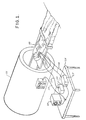
- an MRI facility is schematically illustrated.
- a patient on an examination table 10 is disposed relative to an MRI system 11 for taking MRI images of the patient.
- an all dielectric fiber optic coupler phonocardio and pulse sensor 12 is disposed adjacent the patient for detecting the pulse thereof.
- the sensor 12 is illustrated adjacent the carotid artery in the patient's neck for performing the detection function. It is appreciated that the sensor 12 can be positioned at any other appropriate location on the patient's body.
- An appropriate light source 13, such as a pigtailed light emitting diode (LED) or laser is coupled to the sensor 12 by an optical fiber 14.
- the optical fiber 14 forms the input port of the sensor 12.
- the light source 13 is on an auxiliary stand 15 located a distance from the table 10.
- Optical fibers 16 form the output ports of the sensor 12 and are coupled to electronic detection circuitry 17 on the table 15.
- the electronic detection circuitry 17 provides electrical signals corresponding to the acoustic signals detected by the sensor 12 in a manner to be explained.
- the electrical output of the circuitry 17 is coupled to an oscilloscope 18 for visual observation.
- the electical output of the circuitry 17 is also coupled via a line 19 to the MRI system 11 to provide gated imaging.
- the purpose of the sensor 12 is not primarily to view the pulse but to gate the image of the MRI system.
- the sensor 12 is utilized to time or synchronize the MRI system so that images of a desired area are obtained at "quiet" intervals when the pulse pressure wave is not travelling through the area of interest.
- the pulse pressure wave results in momentary swelling causing spurious effects or artifacts which tend to blur the image thereby resulting in a loss of resolution.
- Figure 2 illustrates an acoustic record of a wrist pulse obtained, in accordance with the invention, by a coupler sensor merely placed on top of the wrist. It is appreciated that electrical leads are not required to be located anywhere near the patient.
- Figure 4 illustrates a spectral analysis of the wrist pulse of Figure 2. A frequency spectrum from 0 to 5 Hz is illustrated. The spectrum was obtained over a 5 minute period with a conventional spectrum analyzer having a bandwidth of 72.6 mHz.
- Figure 3 illustrates heart sounds obtained, in accordance with the invention, with a fiber optic coupler sensor. The sensor was positioned on the patient's chest and the recorded sounds were sensed through the patient's undershirt and dress shirt.
- S1 through S4 refer to the first through fourth heart sounds, respectively.
- the three traces 3A-3C illustrate how frequency filtering reveals different information.
- Waveform 3A illustrates the heart sounds in the frequency range of 10-300 Hz.
- Waveform 3B illustrates the heart sounds in the frequency range of 10-100 Hz and resembles a conventional phonocardiogram.
- Waveform 3C illustrates heart sounds in the frequency range of 1-30 Hz and illustrates the identification of heart sounds as well as a very low frequency chest response probably related to systole. Specifically, the peak M is probably due to a very low frequency chest movement during systole.
- the phonocardio sensor utilized in the present invention is of the type disclosed in U.S. Patent 4,634,858, issued January 6, 1987, entitled “Variable Coupler Fiber Optic Sensor” and assigned to the assignee of the present application. Said Patent 4,634,858 is incorporated herein in its entirety.
- Fiber optic couplers are M ⁇ N port devices which couple light from one of the M input ports to all of the N output ports.
- single mode couplers are 2 ⁇ 2 devices constructed from single mode fibers which operate over the ordinary fiber wavelengths of 633, 850, 1300, and 1550NM.
- the phonocardio sensor generally comprises a 2 ⁇ 2 fused tapered biconical coupler surrounded by a rubber-like medium such as silicon rubber as described in said Patent 4,634,858.
- a rubber-like medium such as silicon rubber as described in said Patent 4,634,858.
- the preferred method of fusing the fibers is described in U.S.-A-4,879,454 which is incorporated herein in its entirety by reference.
- FIG. 5 schematically illustrates a variable coupler fiber optic phonocardio sensor 30 having input fibers 31 and output fibers 32.
- the sensor 30 includes a coupling joint or waist region 33 encapsulated in an encapsulant 34.
- the encapsulant 34 is preferably a room temperature vulcanizing (RTV) silicon rubber such as General Electric RTV-12.
- RTV room temperature vulcanizing
- Light is launched into one of the input fibers 31 by a suitable light source such as a pigtailed fiber optic LED 35.
- a suitable pigtailed laser may be utilized as the light source.
- the light is guided by the input fiber to the coupler joint 33 where it is divided into the two output fibers 32.
- the sensor 30 is constructed such that the light divides into approximately equal portions under quiescent conditions.
- the optical power ratio is then approximately one-to-one.
- the light guided into the output fibers 32 impinge upon photodetectors 36, respectively, which are preferably implemented by photodiodes.
- the ratio of optical power division is linearly related to the stress field at the coupling joint 33.
- stress in the region of the encapsulated coupler joint 33 results in a ratio change in the optical output of the fibers 32.
- This change in ratio is measured by the photodetectors 36 by converting the optical ratio change to a ratio change in voltage.
- the voltage outputs from the photodetectors 36 are differentially amplified at the inverting and non-inverting inputs of a differential amplifier 37.
- the output of the differential amplifier 37 conveniently provides an input to an oscilloscope 38.
- the output ratio of the coupler sensor 30 is extremely sensitive to strain induced in the encapsulant 34 near the coupler joint 33 by the phonocardio audible and infra-sounds to be detected.
- a phonocardio sensor 40 comprising all non-electically conducting components was utilized as a heart/pulse infra-sound and audible sound sensor.
- the sensor was utilized in the acoustically noisy environment of a magnetic resonance imaging system.
- the sensor 40 is comprised of an input optical fiber 41, a coupling, beam splitting or fusion joint 42 and output optical fibers 43.
- the joint 42 is encapsulated in a stress sensitive encapsulant 44 such as fast set two part GE RTV-12.
- the coupler 40 includes a non-metallic structural support member or body 45 preferably comprised of a plastic such as Plexiglas plastic.
- the plastic member 45 includes a large round hole 46 bored through the member 45 and centered thereon.
- PVC polyvinyl chloride
- the PVC film 47 was glued onto the plastic body 45 with quickset epoxy which was then allowed to cure.
- the plastic body 45 with a somewhat wrinkled PVC film 47 was placed into an oven at 50°C for five minutes. This heating process stretched the PVC film 47 tight like a drumhead.
- a heat gun may be utilized instead of the oven. Care, however, must be exercised not to tear the PVC film 47 when rapidly stretching it with a heat gun. It is appreciated, therefore, that the large hole 46 in the plastic member 45 now has a uniform bottom defined by the tight PVC film 47.
- Two grooves or slots 48 are milled into the plastic member 45 and the coupler fiber elements 41, 42 and 43 are tautly fastened into the slots 48 and the hole 46 by a suitable securing means 49.
- a fast cure epoxy or other rigid glue or cement is utilized.
- the joint 42 is surrounded by the RTV encapsulant 44.
- the grooves 48 function to permit the coupling joint 42 to be enclosed approximately in the center of the RTV 44.
- the epoxy securant 49 maintains the joint 42 tight while the RTV 44 is poured into the well formed by the hole 46 and the PVC film 47.
- the RTV encapsulant 44 is permitted to cure and the sensor is then ready for use.
- the purpose of the PVC film 47 is to form a mold surface for the RTV 44 and is not designed to affect the operation of the sensor 40.
- the film 47 could be utilized to provide sensor characteristics which could not be otherwise obtained.
- the film 47 could be utilized to provide additional stiffness.
- the plastic member 45 is provided with rounded corners 50 to facilitate access to regions of the body.
- the sensor 40 appears to provide best performance when resting flat on the body.
- the sensor 40 is preferably disposed on the neck of the patient.
- the sensor 40 is approximately 3" in diameter and approximately 1/8 ⁇ thick.
- a sensor 60 includes an RTV membrane 61 with concave contours 62.
- the sensor 60 also includes non-metallic protective plates 63.
- the concave surfaces 62 are molded into the RTV membrane 61 by wax forms which are later removed by heat or chemicals.
- the sensor 60 thus includes a very thin and very sensitive RTV membrane 61.
- the membrane 61 responds inertially as described in said S.N. 376,342 and is protected from being punctured by the protective plates 63.
- the dimensions of the sensor 60 are approximately the same as the sensor 40 of Figure 6.
- variable coupler fiber optic sensor of said Patent 4,634,858 has been constructed as a tubular sensor and has demonstrated extreme sensitivity. Therefore, a linear phonocardio/pulse sensor is contemplated.
- a linear pulse/phonocardio sensor embodied as a catheter 70 is illustrated.
- the sensor 70 includes a non-metallic body 71 with slots 72 milled therein.
- the input fiber 41, output fibers 43 and the beam splitting joint 42 are anchored in the slots 72 by the epoxy beads 49.
- the fibers are anchored to a structure comprising the body 71 with wax or polymeric film forms to form concave, convex or flat sections as desired.
- RTV fills a cavity in the structure encapsulating the joint 42 and forming a sensitive membrane 73 including concave, convex or flat surfaces as desired.
- One side of the membrane 73 may include a concave surface 74.
- the other side of the membrane 73 may either be concave or flat as indicated by the dashed line 75.
- the sensor 70 includes protective top and bottom plates 76. The sensor 70 may be sufficiently thin to function as a catheter.
- a strap-on sensor 80 illustrates a mechanism for attaching the sensor to the wrist.
- the sensor 80 provides continuous monitoring of the pulse without invasive procedures.
- the elements 41, 42 and 43 are anchored by epoxy beads 49 into milled slots 81 in a non-metallic body 82.
- RTV-12 elastomer is utilized to form a sensitive membrane 83.
- the membrane 83 may be formed with curved surfaces 84 in a manner similar to that described above.
- the sensor 80 includes round protective plates 85.
- a strap 86 such as a velcro strap, is utilized to fasten the sensor 80 to the wrist.
- the sensor 80 is approximately 2 ⁇ in diameter and approximately 1/4 of an inch thick.
- Coupler sensors are sensitive from DC to over 10 KHz and do not exhibit any one-over-frequency type noise. The manufacture of coupler sensors requires only simple and relatively inexpensive methods and materials.
- Inexpensive lasers conventionally utilized with laser discs are appropriate as light sources for the present invention once the laser is pigtailed. Immunity from electrical interference of the sensor utilized in the present invention is particularly desirable in situations encountered by emergency medical technicians. Motors, engines and power lines can render conventional EKG machines useless. Because of the great sensitivity of the above-described sensor, a weak pulse can be sensed in torn limbs which are in danger of circulation loss. Since the sensor does not have any one-over-frequency noise, there are numerous applications of the sensor for low frequency acoustic detection. The spectral analysis of body infra-sound should reveal patterns such as clogging of arteries, the mechanical condition of heart valves and general circulatory condition. This type of data could reveal higher frequency components of infra-sound due to turbulence caused by arterial constriction.
Landscapes
- Health & Medical Sciences (AREA)
- Life Sciences & Earth Sciences (AREA)
- Physics & Mathematics (AREA)
- Engineering & Computer Science (AREA)
- General Health & Medical Sciences (AREA)
- Public Health (AREA)
- Biomedical Technology (AREA)
- Heart & Thoracic Surgery (AREA)
- Medical Informatics (AREA)
- Molecular Biology (AREA)
- Surgery (AREA)
- Animal Behavior & Ethology (AREA)
- Veterinary Medicine (AREA)
- Cardiology (AREA)
- Biophysics (AREA)
- Pathology (AREA)
- Nuclear Medicine, Radiotherapy & Molecular Imaging (AREA)
- Physiology (AREA)
- General Physics & Mathematics (AREA)
- Acoustics & Sound (AREA)
- High Energy & Nuclear Physics (AREA)
- Radiology & Medical Imaging (AREA)
- Signal Processing (AREA)
- Measuring Pulse, Heart Rate, Blood Pressure Or Blood Flow (AREA)
- Magnetic Resonance Imaging Apparatus (AREA)
Applications Claiming Priority (2)
| Application Number | Priority Date | Filing Date | Title |
|---|---|---|---|
| US07/444,920 US5074309A (en) | 1989-12-04 | 1989-12-04 | Device for monitoring cardiovascular signals and fiber optic coupler phonocardio sensor therefor |
| US444920 | 1989-12-04 |
Publications (2)
| Publication Number | Publication Date |
|---|---|
| EP0431842A2 true EP0431842A2 (fr) | 1991-06-12 |
| EP0431842A3 EP0431842A3 (en) | 1991-11-06 |
Family
ID=23766896
Family Applications (1)
| Application Number | Title | Priority Date | Filing Date |
|---|---|---|---|
| EP19900312998 Withdrawn EP0431842A3 (en) | 1989-12-04 | 1990-11-29 | Method of monitoring cardiovascular signals and fiber optic coupler phonocardio sensor therefor |
Country Status (4)
| Country | Link |
|---|---|
| US (1) | US5074309A (fr) |
| EP (1) | EP0431842A3 (fr) |
| JP (1) | JPH03182229A (fr) |
| KR (1) | KR910011222A (fr) |
Cited By (6)
| Publication number | Priority date | Publication date | Assignee | Title |
|---|---|---|---|---|
| EP0568380A1 (fr) * | 1992-04-30 | 1993-11-03 | General Electric Company | Photoplethysmographe à fibre optique pour système d'image de résonance magnétique |
| WO2001065217A1 (fr) * | 2000-02-29 | 2001-09-07 | Cranfield University | Detection d'emission acoustique faisant intervenir un element de couplage de mode a fibres optiques |
| EP1107691A4 (fr) * | 1998-08-24 | 2005-04-06 | Martin C Baruch | Appareil et procede permettant de mesurer le temps de transit d'impulsion |
| GB2407154A (en) * | 2003-10-13 | 2005-04-20 | Univ Cranfield | Acoustic emission sensor based on a fused tapered optical coupler with sharp taper angle |
| EP1865835A4 (fr) * | 2005-04-05 | 2009-10-28 | Hd Medical Group Ltd | Systeme et procedes de declenchement de signaux cardiaques |
| CN103472136A (zh) * | 2013-08-30 | 2013-12-25 | 南京航空航天大学 | 一种基于单模光纤耦合器的声发射传感系统 |
Families Citing this family (22)
| Publication number | Priority date | Publication date | Assignee | Title |
|---|---|---|---|---|
| FR2669754A1 (fr) * | 1990-11-23 | 1992-05-29 | Odam | Moniteur de surveillance des parametres physiologiques vitaux d'un patient en cours d'examen dit irm. |
| DE4218321A1 (de) * | 1991-12-09 | 1993-06-17 | Siemens Ag | Diagnostikanlage |
| US5503161A (en) * | 1993-10-25 | 1996-04-02 | Van Den Heuvel; Raymond C. | Universal medical instrument based on spectrum analysis |
| US6050950A (en) | 1996-12-18 | 2000-04-18 | Aurora Holdings, Llc | Passive/non-invasive systemic and pulmonary blood pressure measurement |
| GB9704737D0 (en) | 1997-03-07 | 1997-04-23 | Optel Instr Limited | Biological measurement system |
| US6063036A (en) * | 1998-02-19 | 2000-05-16 | Li; Pao-Lang | Portable alarm apparatus for sudden heart attack patient |
| US6723054B1 (en) | 1998-08-24 | 2004-04-20 | Empirical Technologies Corporation | Apparatus and method for measuring pulse transit time |
| US6907148B2 (en) | 1998-08-24 | 2005-06-14 | Empirical Technologies Corporation | Sensing apparatus employing variable coupler fiberoptic sensor |
| US6687424B1 (en) | 1998-08-24 | 2004-02-03 | Empirical Technologies Corporation | Sensing pad assembly employing variable coupler fiberoptic sensor |
| US6463187B1 (en) | 1998-08-24 | 2002-10-08 | Empirical Technologies Corporation | Variable coupler fiberoptic sensor and sensing apparatus using the sensor |
| US6706002B1 (en) * | 2000-03-24 | 2004-03-16 | Ilife Systems, Inc. | System and method for remotely monitoring at least one physiological characteristic of a child |
| US6640126B2 (en) * | 2001-02-26 | 2003-10-28 | Toshiba America Mri, Inc. | Acoustic gating monitor for magnetic resonance imaging system |
| US20040116799A1 (en) * | 2002-11-29 | 2004-06-17 | Ravi Srinivasan | Compatibility of accessory to magnetic resonance |
| WO2007002084A2 (fr) * | 2005-06-20 | 2007-01-04 | Susan Russo | Systeme tube medical a detection de position |
| US7873412B2 (en) * | 2007-02-28 | 2011-01-18 | Cardiac Pacemakers, Inc. | Induced current measurement systems and methods |
| US9345888B2 (en) * | 2007-03-09 | 2016-05-24 | Cardiac Pacemakers, Inc. | MRI compatible implantable medical devices and methods |
| US7853318B2 (en) * | 2007-03-14 | 2010-12-14 | Cardiac Pacemakers, Inc. | Cardiac sensing by implantable medical devices during magnetic resonance imaging |
| DE102009038059B4 (de) * | 2009-08-19 | 2015-05-13 | Siemens Aktiengesellschaft | Verfahren zur Korrektur eines Rohsignals im Hinblick auf ein durch Gradientenspulen hervorgerufenes Störsignal in einem Magnetresonanzgerät bei der Bestimmung eines Zeitpunkts im Herzzyklus eines Patienten und Magnetresonanzgerät |
| US20110213263A1 (en) * | 2010-02-26 | 2011-09-01 | Sony Ericsson Mobile Communications Ab | Method for determining a heartbeat rate |
| CN108332841B (zh) * | 2018-04-23 | 2020-02-07 | 哈尔滨工业大学深圳研究生院 | 一种光纤振动传感器 |
| CN110226944B (zh) * | 2019-06-24 | 2020-06-16 | 大连理工大学 | 基于mems技术的微型心音传感器及其应用 |
| CN110772236B (zh) * | 2019-10-08 | 2021-04-20 | 华中科技大学 | 一种基于定向耦合器的切脉传感器及脉象测量装置 |
Family Cites Families (14)
| Publication number | Priority date | Publication date | Assignee | Title |
|---|---|---|---|---|
| US4663185A (en) * | 1984-05-10 | 1987-05-05 | General Electric Company | Novel acrylated polymers |
| GB8418262D0 (en) * | 1984-07-18 | 1984-08-22 | Picker Int Ltd | Nuclear magnetic resonance imaging apparatus |
| US4634858A (en) * | 1984-10-17 | 1987-01-06 | Sperry Corporation | Variable coupler fiberoptic sensor |
| DE3513400A1 (de) * | 1985-04-15 | 1986-10-16 | Philips Patentverwaltung Gmbh, 2000 Hamburg | Optischer bewegungssensor |
| CA1272625A (fr) * | 1985-09-10 | 1990-08-14 | Christopher J. Rowe | Dispositifs optiques |
| US4733931A (en) * | 1985-10-25 | 1988-03-29 | G & H Technology, Inc. | Optical fiber coupler and method of making |
| US4752141A (en) * | 1985-10-25 | 1988-06-21 | Luxtron Corporation | Fiberoptic sensing of temperature and/or other physical parameters |
| US4672976A (en) * | 1986-06-10 | 1987-06-16 | Cherne Industries, Inc. | Heart sound sensor |
| GB2193310A (en) * | 1986-08-01 | 1988-02-03 | Boc Group Plc | Pressure sensor |
| SE8702160L (sv) * | 1987-05-25 | 1988-11-26 | Hoek Instr Ab | Stetoskop foer anvaendning vid magnetresonansdiagnostik m m |
| US4883338A (en) * | 1987-10-15 | 1989-11-28 | Hitachi Cable, Ltd. & Hitachi, Ltd. | Synthetic resin optical fiber |
| US4947865A (en) * | 1987-11-09 | 1990-08-14 | The Hon Group | Sensor support plate with detachable ring |
| US4879454A (en) * | 1988-09-06 | 1989-11-07 | Sperry Marine Inc. | Fiber optic fabrication furnace |
| US4932262A (en) * | 1989-06-26 | 1990-06-12 | General Motors Corporation | Miniature fiber optic pressure sensor |
-
1989
- 1989-12-04 US US07/444,920 patent/US5074309A/en not_active Expired - Lifetime
-
1990
- 1990-11-20 KR KR1019900018768A patent/KR910011222A/ko not_active Withdrawn
- 1990-11-29 EP EP19900312998 patent/EP0431842A3/en not_active Withdrawn
- 1990-11-30 JP JP2330995A patent/JPH03182229A/ja active Pending
Cited By (7)
| Publication number | Priority date | Publication date | Assignee | Title |
|---|---|---|---|---|
| EP0568380A1 (fr) * | 1992-04-30 | 1993-11-03 | General Electric Company | Photoplethysmographe à fibre optique pour système d'image de résonance magnétique |
| EP1107691A4 (fr) * | 1998-08-24 | 2005-04-06 | Martin C Baruch | Appareil et procede permettant de mesurer le temps de transit d'impulsion |
| WO2001065217A1 (fr) * | 2000-02-29 | 2001-09-07 | Cranfield University | Detection d'emission acoustique faisant intervenir un element de couplage de mode a fibres optiques |
| GB2407154A (en) * | 2003-10-13 | 2005-04-20 | Univ Cranfield | Acoustic emission sensor based on a fused tapered optical coupler with sharp taper angle |
| GB2407154B (en) * | 2003-10-13 | 2007-01-10 | Univ Cranfield | Improvements in and relating to fibre optic sensors |
| EP1865835A4 (fr) * | 2005-04-05 | 2009-10-28 | Hd Medical Group Ltd | Systeme et procedes de declenchement de signaux cardiaques |
| CN103472136A (zh) * | 2013-08-30 | 2013-12-25 | 南京航空航天大学 | 一种基于单模光纤耦合器的声发射传感系统 |
Also Published As
| Publication number | Publication date |
|---|---|
| KR910011222A (ko) | 1991-08-07 |
| EP0431842A3 (en) | 1991-11-06 |
| JPH03182229A (ja) | 1991-08-08 |
| US5074309A (en) | 1991-12-24 |
Similar Documents
| Publication | Publication Date | Title |
|---|---|---|
| US5074309A (en) | Device for monitoring cardiovascular signals and fiber optic coupler phonocardio sensor therefor | |
| US6723054B1 (en) | Apparatus and method for measuring pulse transit time | |
| US5239997A (en) | Diagnostic apparatus utilizing low frequency sound waves | |
| Li et al. | Wearable alignment-free microfiber-based sensor chip for precise vital signs monitoring and cardiovascular assessment | |
| AU756142B2 (en) | Apparatus and method for measuring pulse transit time | |
| US4301809A (en) | Esophageal monitoring apparatus | |
| Liang et al. | Wearable and multifunctional self-mixing microfiber sensor for human health monitoring | |
| US5022405A (en) | Stethoscope for use in nuclear magnetic resonance diagnostics | |
| US3908636A (en) | Portable pulse sensor | |
| ES2007041A6 (es) | Aparato electronico para diagnostico medico | |
| DE69916599D1 (de) | Medizinische messvorrichtung | |
| US4972841A (en) | Stethoscope with pulse rate display | |
| Balaji et al. | Stereo-bp: Non-invasive blood pressure sensing with earables | |
| US6836577B2 (en) | Variable coupler fiberoptic sensor and sensing apparatus using the sensor | |
| Nishiyama et al. | Unconstrained pulse pressure monitoring for health management using hetero-core fiber optic sensor | |
| US5129403A (en) | Method and apparatus for detecting and transducing intersaccular acoustic signals | |
| Matsumoto et al. | The development of a fibre optic catheter tip pressure transducer | |
| US6907148B2 (en) | Sensing apparatus employing variable coupler fiberoptic sensor | |
| Mohapatra et al. | IoT enabled distributed cardiac monitoring using Fiber Bragg Grating (FBG) sensing technology | |
| CN211381310U (zh) | 振动传感器及脉搏测量系统 | |
| Wood | Physical response requirements of pressure transducers for the reproduction of physiological phenomena | |
| CZ31953U1 (cs) | Zařízení pro monitorování vitálních funkcí lidského těla v elektromagneticky zarušených prostředích | |
| Martinek et al. | A comparison of probes based on Bragg grating sensor and microphones for heart sounds measurement | |
| Agustiyanto Jr et al. | Use of a singlemode multimode singlemode fiber structure for apex cardiography monitoring | |
| Baruch et al. | Fiber-optic couplers as displacement sensors |
Legal Events
| Date | Code | Title | Description |
|---|---|---|---|
| PUAI | Public reference made under article 153(3) epc to a published international application that has entered the european phase |
Free format text: ORIGINAL CODE: 0009012 |
|
| AK | Designated contracting states |
Kind code of ref document: A2 Designated state(s): CH DE DK FR GB IT LI NL SE |
|
| PUAL | Search report despatched |
Free format text: ORIGINAL CODE: 0009013 |
|
| AK | Designated contracting states |
Kind code of ref document: A3 Designated state(s): CH DE DK FR GB IT LI NL SE |
|
| 17P | Request for examination filed |
Effective date: 19920326 |
|
| STAA | Information on the status of an ep patent application or granted ep patent |
Free format text: STATUS: THE APPLICATION HAS BEEN WITHDRAWN |
|
| 18W | Application withdrawn |
Withdrawal date: 19930118 |