EP0431946A2 - Methode und Gerät zur magneto-optischen Aufzeichnung - Google Patents
Methode und Gerät zur magneto-optischen Aufzeichnung Download PDFInfo
- Publication number
- EP0431946A2 EP0431946A2 EP90313275A EP90313275A EP0431946A2 EP 0431946 A2 EP0431946 A2 EP 0431946A2 EP 90313275 A EP90313275 A EP 90313275A EP 90313275 A EP90313275 A EP 90313275A EP 0431946 A2 EP0431946 A2 EP 0431946A2
- Authority
- EP
- European Patent Office
- Prior art keywords
- layer
- memory layer
- temperature
- reference layer
- memory
- Prior art date
- Legal status (The legal status is an assumption and is not a legal conclusion. Google has not performed a legal analysis and makes no representation as to the accuracy of the status listed.)
- Granted
Links
Images



Classifications
-
- G—PHYSICS
- G11—INFORMATION STORAGE
- G11B—INFORMATION STORAGE BASED ON RELATIVE MOVEMENT BETWEEN RECORD CARRIER AND TRANSDUCER
- G11B11/00—Recording on or reproducing from the same record carrier wherein for these two operations the methods are covered by different main groups of groups G11B3/00 - G11B7/00 or by different subgroups of group G11B9/00; Record carriers therefor
- G11B11/10—Recording on or reproducing from the same record carrier wherein for these two operations the methods are covered by different main groups of groups G11B3/00 - G11B7/00 or by different subgroups of group G11B9/00; Record carriers therefor using recording by magnetic means or other means for magnetisation or demagnetisation of a record carrier, e.g. light induced spin magnetisation; Demagnetisation by thermal or stress means in the presence or not of an orienting magnetic field
- G11B11/105—Recording on or reproducing from the same record carrier wherein for these two operations the methods are covered by different main groups of groups G11B3/00 - G11B7/00 or by different subgroups of group G11B9/00; Record carriers therefor using recording by magnetic means or other means for magnetisation or demagnetisation of a record carrier, e.g. light induced spin magnetisation; Demagnetisation by thermal or stress means in the presence or not of an orienting magnetic field using a beam of light or a magnetic field for recording by change of magnetisation and a beam of light for reproducing, i.e. magneto-optical, e.g. light-induced thermomagnetic recording, spin magnetisation recording, Kerr or Faraday effect reproducing
- G11B11/10502—Recording on or reproducing from the same record carrier wherein for these two operations the methods are covered by different main groups of groups G11B3/00 - G11B7/00 or by different subgroups of group G11B9/00; Record carriers therefor using recording by magnetic means or other means for magnetisation or demagnetisation of a record carrier, e.g. light induced spin magnetisation; Demagnetisation by thermal or stress means in the presence or not of an orienting magnetic field using a beam of light or a magnetic field for recording by change of magnetisation and a beam of light for reproducing, i.e. magneto-optical, e.g. light-induced thermomagnetic recording, spin magnetisation recording, Kerr or Faraday effect reproducing characterised by the transducing operation to be executed
- G11B11/10504—Recording
- G11B11/10506—Recording by modulating only the light beam of the transducer
-
- G—PHYSICS
- G11—INFORMATION STORAGE
- G11B—INFORMATION STORAGE BASED ON RELATIVE MOVEMENT BETWEEN RECORD CARRIER AND TRANSDUCER
- G11B11/00—Recording on or reproducing from the same record carrier wherein for these two operations the methods are covered by different main groups of groups G11B3/00 - G11B7/00 or by different subgroups of group G11B9/00; Record carriers therefor
- G11B11/10—Recording on or reproducing from the same record carrier wherein for these two operations the methods are covered by different main groups of groups G11B3/00 - G11B7/00 or by different subgroups of group G11B9/00; Record carriers therefor using recording by magnetic means or other means for magnetisation or demagnetisation of a record carrier, e.g. light induced spin magnetisation; Demagnetisation by thermal or stress means in the presence or not of an orienting magnetic field
- G11B11/105—Recording on or reproducing from the same record carrier wherein for these two operations the methods are covered by different main groups of groups G11B3/00 - G11B7/00 or by different subgroups of group G11B9/00; Record carriers therefor using recording by magnetic means or other means for magnetisation or demagnetisation of a record carrier, e.g. light induced spin magnetisation; Demagnetisation by thermal or stress means in the presence or not of an orienting magnetic field using a beam of light or a magnetic field for recording by change of magnetisation and a beam of light for reproducing, i.e. magneto-optical, e.g. light-induced thermomagnetic recording, spin magnetisation recording, Kerr or Faraday effect reproducing
- G11B11/10502—Recording on or reproducing from the same record carrier wherein for these two operations the methods are covered by different main groups of groups G11B3/00 - G11B7/00 or by different subgroups of group G11B9/00; Record carriers therefor using recording by magnetic means or other means for magnetisation or demagnetisation of a record carrier, e.g. light induced spin magnetisation; Demagnetisation by thermal or stress means in the presence or not of an orienting magnetic field using a beam of light or a magnetic field for recording by change of magnetisation and a beam of light for reproducing, i.e. magneto-optical, e.g. light-induced thermomagnetic recording, spin magnetisation recording, Kerr or Faraday effect reproducing characterised by the transducing operation to be executed
- G11B11/10517—Overwriting or erasing
- G11B11/10519—Direct overwriting, i.e. performing erasing and recording using the same transducing means
-
- G—PHYSICS
- G11—INFORMATION STORAGE
- G11B—INFORMATION STORAGE BASED ON RELATIVE MOVEMENT BETWEEN RECORD CARRIER AND TRANSDUCER
- G11B11/00—Recording on or reproducing from the same record carrier wherein for these two operations the methods are covered by different main groups of groups G11B3/00 - G11B7/00 or by different subgroups of group G11B9/00; Record carriers therefor
- G11B11/10—Recording on or reproducing from the same record carrier wherein for these two operations the methods are covered by different main groups of groups G11B3/00 - G11B7/00 or by different subgroups of group G11B9/00; Record carriers therefor using recording by magnetic means or other means for magnetisation or demagnetisation of a record carrier, e.g. light induced spin magnetisation; Demagnetisation by thermal or stress means in the presence or not of an orienting magnetic field
- G11B11/105—Recording on or reproducing from the same record carrier wherein for these two operations the methods are covered by different main groups of groups G11B3/00 - G11B7/00 or by different subgroups of group G11B9/00; Record carriers therefor using recording by magnetic means or other means for magnetisation or demagnetisation of a record carrier, e.g. light induced spin magnetisation; Demagnetisation by thermal or stress means in the presence or not of an orienting magnetic field using a beam of light or a magnetic field for recording by change of magnetisation and a beam of light for reproducing, i.e. magneto-optical, e.g. light-induced thermomagnetic recording, spin magnetisation recording, Kerr or Faraday effect reproducing
- G11B11/10502—Recording on or reproducing from the same record carrier wherein for these two operations the methods are covered by different main groups of groups G11B3/00 - G11B7/00 or by different subgroups of group G11B9/00; Record carriers therefor using recording by magnetic means or other means for magnetisation or demagnetisation of a record carrier, e.g. light induced spin magnetisation; Demagnetisation by thermal or stress means in the presence or not of an orienting magnetic field using a beam of light or a magnetic field for recording by change of magnetisation and a beam of light for reproducing, i.e. magneto-optical, e.g. light-induced thermomagnetic recording, spin magnetisation recording, Kerr or Faraday effect reproducing characterised by the transducing operation to be executed
- G11B11/10523—Initialising
-
- G—PHYSICS
- G11—INFORMATION STORAGE
- G11B—INFORMATION STORAGE BASED ON RELATIVE MOVEMENT BETWEEN RECORD CARRIER AND TRANSDUCER
- G11B11/00—Recording on or reproducing from the same record carrier wherein for these two operations the methods are covered by different main groups of groups G11B3/00 - G11B7/00 or by different subgroups of group G11B9/00; Record carriers therefor
- G11B11/10—Recording on or reproducing from the same record carrier wherein for these two operations the methods are covered by different main groups of groups G11B3/00 - G11B7/00 or by different subgroups of group G11B9/00; Record carriers therefor using recording by magnetic means or other means for magnetisation or demagnetisation of a record carrier, e.g. light induced spin magnetisation; Demagnetisation by thermal or stress means in the presence or not of an orienting magnetic field
- G11B11/105—Recording on or reproducing from the same record carrier wherein for these two operations the methods are covered by different main groups of groups G11B3/00 - G11B7/00 or by different subgroups of group G11B9/00; Record carriers therefor using recording by magnetic means or other means for magnetisation or demagnetisation of a record carrier, e.g. light induced spin magnetisation; Demagnetisation by thermal or stress means in the presence or not of an orienting magnetic field using a beam of light or a magnetic field for recording by change of magnetisation and a beam of light for reproducing, i.e. magneto-optical, e.g. light-induced thermomagnetic recording, spin magnetisation recording, Kerr or Faraday effect reproducing
- G11B11/10582—Record carriers characterised by the selection of the material or by the structure or form
- G11B11/10586—Record carriers characterised by the selection of the material or by the structure or form characterised by the selection of the material
Definitions
- the invention relates to a method and an apparatus for overwritable magneto-optical recording.
- An optical disk allows higher-density recording than a magnetic disk, but is inferior in high-speed performance, with an access time that is up to ten times as long.
- a method for remedying this is overwriting. Conventionally, rewriting is done during three turns or passes: erasing on the first turn, recording on the second, and error checking on the third. In contrast, overwriting will allow rewriting during only two turns, by erasing and recording simultaneously.
- One approach that uses two heads for erasing and recording to permit pseudo-overwriting has been proposed for overwritable magneto-optical recording. However, the system is complicated. Another method that allows simultaneous erasing and recording of adjacent tracks with two laser spots cannot be used in sector-based writing.
- a field modulation method, a light modulation method using an exchange-coupled double-layered film, and a light modulation method using a demagnetizing field have been proposed as direct overwrite methods.
- the light modulation overwrite method using an exchange-coupled double-layered film is superior to the field modulation system in that it provides easy high-speed modulation and allows a wide space between the bias magnet and the disk.
- the properties of the media must be controlled accurately, and that the laser power margins or tolerances for reading and writing become smaller.
- the double-layered film overwrite method disclosed in Japanese Published Unexamined Patent Application (PUPA) No. 62-175948 is explained below.
- the recording layer used in this method consists of two layers, a memory layer and a reference layer, which are exchange-coupled. Overwriting is performed by utilizing the difference in temperature dependence of the coercive forces (Hc) of the two layers.
- Figure 15 shows the magnetic properties of an overwritable disk
- Figure 16 shows a method of overwriting on this type of medium. Basically, this method utilizes the magnetic properties that the coercive force of the reference layer (Hca2) is smaller than that of the memory layer (Hca2) at room temperature (Tamb1) and that the Curie temperature of the reference layer (Tc2) is higher than that of the memory layer (Tc1).
- the magnitude of the external field Hini applied before laser emission is set so that Hca2 ⁇ Hini ⁇ Hca1.
- the memory layer retains the recorded information, because Hca1 is large.
- the temperature of the recording layer TL becomes Tc1 ⁇ TL ⁇ Tc2.
- the magnetization of the reference layer is not reversed by the weak external field Hb, so that the magnetization of the memory layer is oriented downward during the cooling process, following the magnetization of the reference layer, as shown in Figure 16 (erasing).
- the directions of the magnetic moments of similar atoms become essentially parallel to each other, in this case the directions of magnetization also become parallel to each other.
- the temperature of the recording layer TH becomes higher than Tc2.
- the magnetization of the reference layer is reversed by the external field Hb, so that during the cooling process (writing) the magnetization of the memory layer is oriented in the same direction, that is, downward in Figure 26.
- Recording by using the magnetization of the reference layer is hereinafter referred to as the "L process” and recording by using an external field is referred to as the "H process.”
- the name of each process is derived from the temperature of the reference layer.
- Figure 17 shows the experimental results of the overwriting characteristics for a double-layered film whose memory layer consists of TbFeCo and whose reference layer consists of DyFeCo, reported by Matsumoto Hiroyuki, et al. in "Magneto-optical Disk for Direct Overwrite by Light Power Modulation Method," Symposium on Optical Memory '88, Article Collection 45 (1988).
- the right side of Figure 17 shows the carrier level in the H process, which is a recording process with high laser power. The results are obtained by using a modulated light of 1 MHz to record on the medium with its data erased.
- the left side of Figure 17 shows the signal level of data left unerased during the L process, which is an erasing process with low laser power. The results are obtained by using CW light to erase signals of 1 MHz written onto a medium.
- the magnetic recording medium disclosed in Japanese PUPA No. 62-80847 comprises a memory layer for retaining domains with desired field orientations representative of binary data, a reference layer for providing a bias field as a function of the temperature for obtaining the domains of desired magnetic field orientations in the memory layer, and a thermal isolation layer for isolating the memory layer from the reference layer.
- Laser pulses are emitted from the memory-layer side of the medium and the durations are changed in response to recording or erasing.
- the duration is typically decreased to 50 nanoseconds so that the memory layer is heated to above the Curie temperature, while the reference layer, which is isolated by the thermal isolation layer, is held at a relatively low temperature.
- duration is typically increased to 500-600 nanoseconds so as to heat the reference layer to a sufficiently high temperature.
- sufficiently long durations of laser pulses for heating the reference layer which is isolated by the thermal insulation layer, require slow disk rotation, hence prevent an increase in the data transfer rate.
- interposition of the thermal isolation layer is considered to make it impossible to utilize the exchange-coupling between the memory layer and the reference layer described in Japanese PUPA No. 62-175948.
- the present invention provides a method for magneto-optical recording using a magnetic recording medium comprising a memory layer and a reference layer laminated either directly or via an intermediate thermally conductive layer onto the memory layer, the method comprising selectively controlling the temperature difference between the reference layer and the memory layer by altering the duration of laser pulses generated by a laser pulse emission means and incident on the magnetic recording medium.
- the present invention enables data to be recorded in the memory layer by changing the temperature gradients across the thickness of the recording medium and thus controlling the temperature of the reference layer.
- the method can be for recording a desired set of binary data and the selective controlling of the temperature diffference can selectively control the magnetic properties of the reference layer to record the desired binary data in the memory layer.
- a first predetermined value of the duration of the laser pulses can be used to induce a temperature difference between the memory layer and the reference layer whilst a second longer predetermined value of the laser pulses induces no substantial temperature difference between the layers.
- the temperature difference between the layers is controlled by selecting either the first or the second predetermined value in accordance with the binary data.
- a method for magneto-optical recording by using a magnetic recording medium and means for emitting a pulsed laser, the magnetic recording medium comprising a memory layer for retaining domains with field orientations representative of binary data and a reference layer laminated directly or via an intermediate thermally conductive layer onto the memory layer, where the magnetic properties of the reference layer varies with the temperature in a different way from those of the memory layer, the domains of desired magnetization orientations being set in the memory layer by utilizing the change in magnetic property of the reference layer resulting from the temperature change, the method comprising the steps of:
- another aspect of the invention enables apparatus to be provided for magneto-optical recording by using a magnetic recording medium and means for emitting a pulsed laser, the magnetic recording medium comprising a memory layer for retaining domains with field orientations representative of binary data and a reference layer laminated directly or via an intermediate thermally conductive layer onto the memory layer, where the magnetic properties of the reference layer varies with the temperature in a different way from those of the memory layer, the domains of desired magnetization orientations being set in the memory layer by utilizing the change in magnetic property of the reference layer resulting from the temperature change, comprises:
- This scheme makes overwrite recording possible by utilizing the exchange-coupling between the memory layer and the reference layer. It also makes it possible to increase the laser power margin by using in the L process short pulses that produce a sufficiently large temperature difference between the above two layers, while using laser pulses of long duration in the H process so that the temperature of the memory layer and that of the reference layer become high simultaneously, as in conventional cases.
- the conventional light modulation overwrite method using an exchange-coupled double-layered film the characteristics of data writing/readout are vulnerable to fluctuations in laser power and ambient temperature, and cannot cope with fluctuations in the media sensitivity, which makes the method impractical.
- the present invention remedies these problems and makes the the multilayered film overwriting method feasible.
- a further advantage of the present invention is that the materials selected for the memory layer and the reference layer can have substantially the same Curie temperature thereby widening the choice of materials for the medium.
- a magneto-optical recording medium for use with the above-described methods and apparatus, the medium comprising a memory layer and a reference layer either laminated directly or via an intermediate thermally conductive layer on to the memory layer.
- the disk structure shown in Table 1 is considered as an example of an exchange-coupled double-layer medium.
- a relatively thick reference layer with a large thermal conductivity is used under the memory layer.
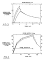
- Figures 1 - 4 show the simulated change in peak temperature with time on the recording surface of a disk whose structure is outlined in Table 1.
- the pulse widths of the emitted lasers are assumed to be 1 nanosecond for a short pulse and 100 nanoseconds for a long pulse.
- the vertical axis shows the temperature change from room temperature. The values are calculated for the interface between the protective and memory layers, the memory and reference layers, and the reference and protective layers, then normalized by the peak power of the emitted laser.
- the 1-ns pulse raises the maximum temperature of the reference layer on the side opposite to the laser emission, to only 47% of that of the laser emission side of the memory layer, and induces a temperature gradient along the thickness, while the 100-ns pulse raises the maximum temperature of the reference layer to 93% of that of the memory layer, inducing no substantial temperature gradient.
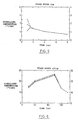
- Figures 5 and 6 show the simulation results for the temperature rise in a disk of the same structure as in Table 1, except that the thickness of the reference layer is 1000 A. A sufficiently large temperature difference is induced by the 1-ns pulse along the thickness, but not by the 100-ns pulse.
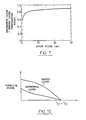
- Figure 7 shows the simulation results for the ratio of the temperature rise at the midpoint of the reference layer to that at the midpoint of the memory layer of the disk outlined in Table 1 when it is irradiated by pulses of various durations.
- Short pulses induce temperature gradients because the heating of the recording layer is completed before the whole layer reaches thermal equilibrium.
- both the memory and reference layers are heated to nearly the same temperature in both H and L processes, and writing/erasing is effected by using only the difference in the Curie temperatures of the medium's layers, as shown in Figure 15.
- the present invention takes advantage of the change in the temperature gradients in the recording layer by using the method described in D.1 to carry out overwriting.
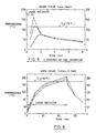
- the L process is carried out by utilizing the temperature gradients and raising the temperature of the memory layer only sufficiently to change its magnetization direction (see Figure 8).
- the temperature rise in the reference layer is small, the coercive force of the layer is large enough to keep its magnetization direction in the initial state.
- both the memory and reference layers can be heated to sufficiently high temperatures. Therefore, the coercive forces of both layers become small, and the H process can be carried out (see Figure 9) to change their magnetization directions. In this case, it is possible in principle to overwrite even if the Curie temperatures of the memory layer and the reference layer are equal, as shown in Figure 10.
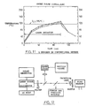
- Figure 11 shows as reference the simulation results for a case in which the long pulse is used even in the L process, as before.
- the laser power margins in the L/H processes are estimated for the case of a double-layered film of the type shown in Figure 15 on the assumption that the Curie temperature of the memory layer Tc1 equals 135°C that of the reference layer Tc2 200°C, and the room temperature Ta 20°C.
- the L process will occur when a half or more of the memory layer is heated to a temperature of Tc1 or more while a half of the reference layer is less than Tc2 in temperature
- the H process will occur when a half of the reference layer is heated to a temperature of Tc2 or more.
- the range of the laser power PL that causes the L process is 58 mW ⁇ PL ⁇ 132 mW (pulse width: 1 nanosecond)
- the range of the laser power PH that causes the H process is 8.7 mW ⁇ PH (pulse width: 100 nanoseconds)
- the ranges of the laser power in the H and L processes can be made widely different by this method.
- the invention allows overwriting by controlling the temperature gradients of the memory and reference layers, and can improve the laser power margin for data write/read. This permits overwriting whose write/read characteristics are resistant to variations in the laser power and the ambient temperature, and also increases the tolerance toward fluctuation in the sensitivity of the medium.
- each layer was estimated from the sputtering time.
- a laser pulse with a full-width half-maximum diameter of 0.47 m was emitted.
- the time width of the laser pulse was controlled by changing the time width of the current pulse flowing through the laser diode.
- the bias magnetic field was kept at 110 Oe. Domains written in the memory layer were observed with a polarizing microscope with an oil-immersion objective lens. Observation of domains make it possible to tell whether the L process has been achieved or not.
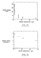
- Figure 13 shows the laser power range of the L process for several different pulse durations.
- Figure 14 shows the relationship between the pulse duration and the ratio of the maximum laser power to the minimum one in the L process, on the basis of the experimental results shown in Figure 13.
- the ratio increases with a decrease in the pulse duration.
- a 2.7-ns pulse expands the range to 1.8 times wider than that of a 56-ns pulse.
- the invention makes it possible to overwrite a medium by controlling the temperature of the reference layer with no thermal isolation layer interposed between the memory and reference layers. It is also possible to expand the margin of the laser power because data is recorded in the memory layer while the reference layer is kept at a low temperature.
- the magnetic recording medium comprising a memory layer for retaining domains with field orientations representative of binary data, and a reference layer laminated directly or via an intermediate thermally conductive layer onto the memory layer, where the magnetic properties of the reference layer vary with the temperature in a different way from those of the memory layer, the domains of desired magnetization orientations being set in the memory layer by utilizing the change in magnetic property of the reference layer resulting from the temperature change, comprising the steps of:
- a first value for inducing temperature gradients along the thickness of said recording medium and a second value for inducing no substantial temperature gradients can be predetermined as the durations of the laser pulses, and either of said first and second values is selected as the duration of the laser pulse generated by said laser pulse emission means according to the binary data to be recorded in said memory layer.
- an apparatus for magneto-optical recording using a magnetic recording medium and means for emitting a pulsed laser comprising a memory layer for retaining domains with field orientations representative of binary data, and a reference layer laminated directly or via an intermediate thermally conductive layer onto the memory layer, where the magnetic properties of the reference layer vary with the temperature in a different way from those of the memory layer, the domains of desired magnetization orientations being set in the memory layer by utilizing the magnetic property of the reference layer resulting from the temperature change, comprising:
Applications Claiming Priority (2)
| Application Number | Priority Date | Filing Date | Title |
|---|---|---|---|
| JP1317915A JP2575511B2 (ja) | 1989-12-08 | 1989-12-08 | 光磁気記録方法及び装置 |
| JP317915/89 | 1989-12-08 |
Publications (3)
| Publication Number | Publication Date |
|---|---|
| EP0431946A2 true EP0431946A2 (de) | 1991-06-12 |
| EP0431946A3 EP0431946A3 (en) | 1992-09-09 |
| EP0431946B1 EP0431946B1 (de) | 1996-02-28 |
Family
ID=18093467
Family Applications (1)
| Application Number | Title | Priority Date | Filing Date |
|---|---|---|---|
| EP90313275A Expired - Lifetime EP0431946B1 (de) | 1989-12-08 | 1990-12-06 | Methode und Gerät zur magneto-optischen Aufzeichnung |
Country Status (4)
| Country | Link |
|---|---|
| US (1) | US5329505A (de) |
| EP (1) | EP0431946B1 (de) |
| JP (1) | JP2575511B2 (de) |
| DE (1) | DE69025562T2 (de) |
Families Citing this family (5)
| Publication number | Priority date | Publication date | Assignee | Title |
|---|---|---|---|---|
| JPH06236587A (ja) * | 1992-05-19 | 1994-08-23 | Nikon Corp | 再生専用型の光磁気ディスク、その再生方法 及び再生装置 |
| JPH06131722A (ja) * | 1992-10-16 | 1994-05-13 | Canon Inc | 光磁気記録媒体およびその記録方法 |
| JPH06236589A (ja) * | 1993-02-10 | 1994-08-23 | Canon Inc | 光磁気記録方法および光磁気再生方法及び光磁気記録媒体 |
| JP2002312936A (ja) * | 2001-04-19 | 2002-10-25 | Matsushita Electric Ind Co Ltd | 光記録媒体の記録方法および情報が記録された光記録媒体 |
| US12431165B1 (en) * | 2024-10-11 | 2025-09-30 | Seagate Technology Llc | Optical magnetic recording system, writer, media, and method |
Family Cites Families (16)
| Publication number | Priority date | Publication date | Assignee | Title |
|---|---|---|---|---|
| JPS61276103A (ja) * | 1985-05-31 | 1986-12-06 | Canon Inc | 光磁気メモリ記録方法 |
| JP2521908B2 (ja) * | 1985-06-11 | 1996-08-07 | 株式会社ニコン | オ―バ―ライト可能な光磁気記録方法、それに使用される光磁気記録装置及び光磁気記録媒体、並びに変調方法、変調装置及び光磁気記録媒体 |
| US4794560A (en) * | 1985-09-30 | 1988-12-27 | International Business Machines Corporation | Eraseable self biasing thermal magneto-optic medium |
| JPH0695404B2 (ja) * | 1985-12-27 | 1994-11-24 | ソニー株式会社 | 光磁気記録方法 |
| US4882718A (en) * | 1986-03-07 | 1989-11-21 | Movid Information Technology, Inc. | Single-head, direct overwrite magneto-optic system and method |
| JP2579631B2 (ja) * | 1986-03-27 | 1997-02-05 | キヤノン株式会社 | 光磁気記録方法 |
| CA1322408C (en) * | 1986-08-20 | 1993-09-21 | Tomiji Tanaka | Thermomagnetic recording method applying power modulated laser on a magnetically coupled double layer structure of perpendicular anisotropy film |
| JP2570270B2 (ja) * | 1986-10-08 | 1997-01-08 | 株式会社ニコン | ツービームによる光磁気記録方法及び装置 |
| JPS63155449A (ja) * | 1986-12-19 | 1988-06-28 | Canon Inc | 光磁気記録方法 |
| JPS63266656A (ja) * | 1986-12-26 | 1988-11-02 | Matsushita Electric Ind Co Ltd | 光磁気記録媒体およびその記録方法 |
| US5051970A (en) * | 1987-05-08 | 1991-09-24 | Nippon Telegraph And Telephone Corporation | Magneto-optic recording system with overwrite capability |
| US5187694A (en) * | 1987-08-21 | 1993-02-16 | Kabushiki Kaisha Toshiba | Magneto-optical recording medium comprising recording layer and thermal bias layer, and method for recording, erasing and overwriting on the medium |
| EP0315415B1 (de) * | 1987-11-02 | 1993-08-18 | Fujitsu Limited | Gleichzeitiges Löschen und erneutes Einschreiben einer Information in einen magnetooptischen Speicher |
| US5144601A (en) * | 1987-11-02 | 1992-09-01 | Fujitsu Limited | Magneto-optical overwriting methods using erasing pulses, each of which has a higher frequency and narrower width than that of the overwriting pulses |
| EP0316188A3 (de) * | 1987-11-12 | 1990-10-31 | MOVID Information Technology, Inc. | Verfahren und Vorrichtung zum gleizeitigen Löschen und erneutem Einschreiben von digitalen Daten in ein magnetooptisches Speichermedium mit Verfahren zum gleichzeitigen streifenweisen Löschen und Einschreiben verlängerter Domänen und ein einzelköpfiges magnetooptisches Verfahren zum gleichzeitigen Löschen und Einschreiben |
| US5175714A (en) * | 1988-09-30 | 1992-12-29 | Kabushiki Kaisha Toshiba | Method of magneto-optically recording/erasing information and magneto-optical information storage medium including recording and bias layers satisfying certain conditions |
-
1989
- 1989-12-08 JP JP1317915A patent/JP2575511B2/ja not_active Expired - Fee Related
-
1990
- 1990-12-06 DE DE69025562T patent/DE69025562T2/de not_active Expired - Fee Related
- 1990-12-06 EP EP90313275A patent/EP0431946B1/de not_active Expired - Lifetime
-
1993
- 1993-08-18 US US08/109,015 patent/US5329505A/en not_active Expired - Lifetime
Also Published As
| Publication number | Publication date |
|---|---|
| EP0431946B1 (de) | 1996-02-28 |
| EP0431946A3 (en) | 1992-09-09 |
| JPH03183048A (ja) | 1991-08-09 |
| DE69025562T2 (de) | 1996-09-19 |
| US5329505A (en) | 1994-07-12 |
| JP2575511B2 (ja) | 1997-01-29 |
| DE69025562D1 (de) | 1996-04-04 |
Similar Documents
| Publication | Publication Date | Title |
|---|---|---|
| EP0217096B1 (de) | Löschbares, selbstpolarisiertes, thermisches magnetooptisches Medium | |
| EP0291248B1 (de) | Vorrichtung und Aufzeichnungsträger zur magneto-optischen Aufzeichnung | |
| US4882718A (en) | Single-head, direct overwrite magneto-optic system and method | |
| JPH0434217B2 (de) | ||
| CA1320269C (en) | Magneto-optic recording structure and method | |
| US5323374A (en) | Method of magneto-optical recording | |
| JPH05101471A (ja) | 光磁気記録再生方法 | |
| JPH01251357A (ja) | 帯状消去及び細長磁区記録のための直接書換え型磁気光学システム、及びシングルヘッド直接書換え型磁気光学システムを含む磁気光学的記録媒体に記録されたディジタルデータのための直接書換え方法及び装置 | |
| EP0431946A2 (de) | Methode und Gerät zur magneto-optischen Aufzeichnung | |
| EP0333462A2 (de) | Magneto-optisches Aufnahmesystem,dessen Datenträger eine Kontrollschicht ohne Bereiche aufweisst | |
| KR100238692B1 (ko) | 광자기기록매체 | |
| KR0143541B1 (ko) | 광자기 기록 방법 | |
| JP3554083B2 (ja) | 光磁気記録媒体及び該媒体の情報記録方法 | |
| EP0422783B1 (de) | Magnetooptische Aufzeichnung | |
| EP0328667B1 (de) | Magneto-optischer speicher | |
| JP2788578B2 (ja) | 光学的データ記憶媒体及びその製造方法 | |
| KR960015209B1 (ko) | 광자기 기록 방법 및 광자기 메모리 소자 | |
| US5528564A (en) | Direct overwrite magneto-optic system for strip erasing and recording elongated domains | |
| JP3015476B2 (ja) | 光磁気記録方法及び光磁気記録媒体 | |
| JPH04105236A (ja) | 磁気記録方式及び消去方式及び読出方式 | |
| Hashimoto et al. | Direct overwriting capability of magneto‐optical disks | |
| US20050002282A1 (en) | Information recording method capable of forming micro marks by optical modulation | |
| Nakaoki et al. | DOUBLE-CAPACITY OVERWRITABLE MAGNETO-OPTICAL DISK USING MAGNETIC TRIPLE-LAYER FILM | |
| JPH07130030A (ja) | オーバーライト可能な光磁気記録方法、光磁気記録媒体 及び光磁気記録装置 | |
| JPH09282726A (ja) | 光磁気記録媒体 |
Legal Events
| Date | Code | Title | Description |
|---|---|---|---|
| PUAI | Public reference made under article 153(3) epc to a published international application that has entered the european phase |
Free format text: ORIGINAL CODE: 0009012 |
|
| AK | Designated contracting states |
Kind code of ref document: A2 Designated state(s): DE FR GB |
|
| 17P | Request for examination filed |
Effective date: 19911018 |
|
| PUAL | Search report despatched |
Free format text: ORIGINAL CODE: 0009013 |
|
| AK | Designated contracting states |
Kind code of ref document: A3 Designated state(s): DE FR GB |
|
| 17Q | First examination report despatched |
Effective date: 19940428 |
|
| GRAA | (expected) grant |
Free format text: ORIGINAL CODE: 0009210 |
|
| AK | Designated contracting states |
Kind code of ref document: B1 Designated state(s): DE FR GB |
|
| REF | Corresponds to: |
Ref document number: 69025562 Country of ref document: DE Date of ref document: 19960404 |
|
| ET | Fr: translation filed | ||
| PLBE | No opposition filed within time limit |
Free format text: ORIGINAL CODE: 0009261 |
|
| STAA | Information on the status of an ep patent application or granted ep patent |
Free format text: STATUS: NO OPPOSITION FILED WITHIN TIME LIMIT |
|
| 26N | No opposition filed | ||
| PGFP | Annual fee paid to national office [announced via postgrant information from national office to epo] |
Ref country code: GB Payment date: 20011210 Year of fee payment: 12 |
|
| PGFP | Annual fee paid to national office [announced via postgrant information from national office to epo] |
Ref country code: DE Payment date: 20011211 Year of fee payment: 12 |
|
| PGFP | Annual fee paid to national office [announced via postgrant information from national office to epo] |
Ref country code: FR Payment date: 20011218 Year of fee payment: 12 |
|
| REG | Reference to a national code |
Ref country code: GB Ref legal event code: IF02 |
|
| PG25 | Lapsed in a contracting state [announced via postgrant information from national office to epo] |
Ref country code: GB Free format text: LAPSE BECAUSE OF NON-PAYMENT OF DUE FEES Effective date: 20021206 |
|
| PG25 | Lapsed in a contracting state [announced via postgrant information from national office to epo] |
Ref country code: DE Free format text: LAPSE BECAUSE OF NON-PAYMENT OF DUE FEES Effective date: 20030701 |
|
| GBPC | Gb: european patent ceased through non-payment of renewal fee | ||
| PG25 | Lapsed in a contracting state [announced via postgrant information from national office to epo] |
Ref country code: FR Free format text: LAPSE BECAUSE OF NON-PAYMENT OF DUE FEES Effective date: 20030901 |
|
| REG | Reference to a national code |
Ref country code: FR Ref legal event code: ST |