EP0432084B1 - Spiralverdichterkurbelwelle mit Lager und Gegengewicht - Google Patents
Spiralverdichterkurbelwelle mit Lager und Gegengewicht Download PDFInfo
- Publication number
- EP0432084B1 EP0432084B1 EP90630195A EP90630195A EP0432084B1 EP 0432084 B1 EP0432084 B1 EP 0432084B1 EP 90630195 A EP90630195 A EP 90630195A EP 90630195 A EP90630195 A EP 90630195A EP 0432084 B1 EP0432084 B1 EP 0432084B1
- Authority
- EP
- European Patent Office
- Prior art keywords
- counterweight
- scroll
- shaft
- crank
- rotor
- Prior art date
- Legal status (The legal status is an assumption and is not a legal conclusion. Google has not performed a legal analysis and makes no representation as to the accuracy of the status listed.)
- Expired - Lifetime
Links
- XEEYBQQBJWHFJM-UHFFFAOYSA-N Iron Chemical compound [Fe] XEEYBQQBJWHFJM-UHFFFAOYSA-N 0.000 claims 2
- 238000009434 installation Methods 0.000 claims 1
- 229910052742 iron Inorganic materials 0.000 claims 1
- 239000012530 fluid Substances 0.000 description 3
- 230000013011 mating Effects 0.000 description 2
- 229910001141 Ductile iron Inorganic materials 0.000 description 1
- 238000004378 air conditioning Methods 0.000 description 1
- 238000010276 construction Methods 0.000 description 1
- 230000001066 destructive effect Effects 0.000 description 1
- 230000000694 effects Effects 0.000 description 1
- 238000004519 manufacturing process Methods 0.000 description 1
- 239000000463 material Substances 0.000 description 1
- 230000002035 prolonged effect Effects 0.000 description 1
- 239000003507 refrigerant Substances 0.000 description 1
- 238000005057 refrigeration Methods 0.000 description 1
- 230000001052 transient effect Effects 0.000 description 1
- 239000011800 void material Substances 0.000 description 1
Images
Classifications
-
- F—MECHANICAL ENGINEERING; LIGHTING; HEATING; WEAPONS; BLASTING
- F04—POSITIVE - DISPLACEMENT MACHINES FOR LIQUIDS; PUMPS FOR LIQUIDS OR ELASTIC FLUIDS
- F04C—ROTARY-PISTON, OR OSCILLATING-PISTON, POSITIVE-DISPLACEMENT MACHINES FOR LIQUIDS; ROTARY-PISTON, OR OSCILLATING-PISTON, POSITIVE-DISPLACEMENT PUMPS
- F04C18/00—Rotary-piston pumps specially adapted for elastic fluids
- F04C18/02—Rotary-piston pumps specially adapted for elastic fluids of arcuate-engagement type, i.e. with circular translatory movement of co-operating members, each member having the same number of teeth or tooth-equivalents
-
- F—MECHANICAL ENGINEERING; LIGHTING; HEATING; WEAPONS; BLASTING
- F04—POSITIVE - DISPLACEMENT MACHINES FOR LIQUIDS; PUMPS FOR LIQUIDS OR ELASTIC FLUIDS
- F04C—ROTARY-PISTON, OR OSCILLATING-PISTON, POSITIVE-DISPLACEMENT MACHINES FOR LIQUIDS; ROTARY-PISTON, OR OSCILLATING-PISTON, POSITIVE-DISPLACEMENT PUMPS
- F04C23/00—Combinations of two or more pumps, each being of rotary-piston or oscillating-piston type, specially adapted for elastic fluids; Pumping installations specially adapted for elastic fluids; Multi-stage pumps specially adapted for elastic fluids
- F04C23/008—Hermetic pumps
-
- F—MECHANICAL ENGINEERING; LIGHTING; HEATING; WEAPONS; BLASTING
- F04—POSITIVE - DISPLACEMENT MACHINES FOR LIQUIDS; PUMPS FOR LIQUIDS OR ELASTIC FLUIDS
- F04C—ROTARY-PISTON, OR OSCILLATING-PISTON, POSITIVE-DISPLACEMENT MACHINES FOR LIQUIDS; ROTARY-PISTON, OR OSCILLATING-PISTON, POSITIVE-DISPLACEMENT PUMPS
- F04C29/00—Component parts, details or accessories of pumps or pumping installations, not provided for in groups F04C18/00 - F04C28/00
- F04C29/0021—Systems for the equilibration of forces acting on the pump
-
- F—MECHANICAL ENGINEERING; LIGHTING; HEATING; WEAPONS; BLASTING
- F05—INDEXING SCHEMES RELATING TO ENGINES OR PUMPS IN VARIOUS SUBCLASSES OF CLASSES F01-F04
- F05C—INDEXING SCHEME RELATING TO MATERIALS, MATERIAL PROPERTIES OR MATERIAL CHARACTERISTICS FOR MACHINES, ENGINES OR PUMPS OTHER THAN NON-POSITIVE-DISPLACEMENT MACHINES OR ENGINES
- F05C2201/00—Metals
- F05C2201/04—Heavy metals
- F05C2201/0433—Iron group; Ferrous alloys, e.g. steel
- F05C2201/0436—Iron
- F05C2201/0439—Cast iron
- F05C2201/0442—Spheroidal graphite cast iron, e.g. nodular iron, ductile iron
Definitions
- the present invention relates to a scroll compressor.
- the invention relates to rotating pumps or compressors of the scroll type, and is more particularly directed to an improved construction involving an integral shaft and counterweight.
- a scroll-type compressor or similar machine comprises a pair of mating scrolls, each of which has an involute spiral wrap of similar shape, mounted on respective base plates. Normally, one scroll is held fixed, and the other is orbited to revolve, but not rotate, being held by an Oldham ring or other anti-rotating structure.
- the walls of the two involute wraps define crescent-shaped volumes which become smaller and smaller and move from the outside to the center of the mating scrolls as the orbiting scroll revolves.
- a compressible fluid such as a refrigerant gas, can be introduced at the periphery of the spiral wraps, and is compressed as it is moved under the orbiting motion of the device. The compressed fluid is then discharged at the center. By introducing a compressed fluid at the center and permitting its expansion to drive the device, the scroll machine can be used as a motor.
- EP-A-165714 discloses a scroll compressor in which the shaft is rotationally supported in a support frame with an upper bearing portion of the shaft. A counterweight integrally formed with the shaft is disposed between the support frame and the crank.
- JP-A-1 170 779 there is described a scroll compressor according to the preamble of claim 1.
- JP-A-1 170 779 describes a scroll compressor of the type including a shell which contains a fixed scroll and an orbiting scroll which is disposed off the axis of the fixed scroll for revolving about the axis of the fixed scroll, rotation-preventing means for holding the orbiting scroll against rotation but permitting it to revolve in an orbiting motion, an electric motor stator mounted within said shell and having a cylindrical passage therethrough of a predetermined radius, and an electric motor rotor assembly rotatably journalled within the shell for driving said orbiting scroll in its orbiting motion.
- the rotor assembly includes a crankshaft assembly and a generally cylindrical rotor mounted on the crankshaft assembly and fitting in the generally cylindrical passage of the stator.
- the crankshaft assembly has an elongated shaft, a crank situated at an upper end of the shaft and that it journalled in a journal housing member beneath the orbiting scroll, and a counterweight which balances the off-axis orbiting motion of the orbiting scroll, the counterweight being formed immediately adjacent the position of the crank, the rotor assembly being the single structure within the predetermined radius between the motor stator and the journal housing member.
- the crank includes eccentric mounting means for driving the orbiting scroll and imparting the orbiting motion thereto.
- a lower bearing rotatably journals a lower end of the shaft, the lower bearing being disposed below the rotor assembly.
- the counterweight is a separate part that must be attached to the rotor or shaft, an additional assembly step is required. Also, the counterweight can possibly become loose under severe use or after prolonged operation, thus limiting the reliability of the compressor.
- the scroll compressor of the invention is characterized by the features set forth in the characterizing portion of claim 1.
- the counterweight is integrally formed with the shaft and is disposed below the crank on the shaft, the radial extent of the counterweight being no greater than the radius of the stator passage and the gas discharge path being located separate from the crank.
- a scroll-type compressor is provided with a rotor shaft that is fabricated so as to have an integral upper bearing and an integral counterweight.
- the scroll compressor has a fixed scroll mounted in the housing and an orbiting scroll which is disposed off the axis of the fixed scroll to revolve about the axis of the fixed scroll.
- a rotation-preventing mechanism holds the orbiting scroll against rotation but permits it to revolve in an orbiting motion.
- An electric motor drive for the compressor has a stator armature that is mounted within the housing.
- the stator has a cylindrical passage through it of a predetermined radius to accommodate a rotor assembly that is rotationally journaled within the housing.
- a generally cylindrical rotor is mounted on the shaft and fits into the generally cylindrical passage of the stator, leaving a small annular gap.
- the bearing serves as a crank and has an off-axis void on its upper surface into which fits a stem of the orbiting scroll.
- a radial compliance device can favorably be employed here.
- the counterweight which is in the form of a segment of a cylinder and which is disposed radially opposite the offset represented by the orbiting scroll.
- the counterweight is disposed entirely within a radius equal to the predetermined radius of the stator passage. This permits the rotor assembly to be installed from below by inserting it through the stator.
- a rotor counterweight in the form of a half ring, is mounted onto the lower end of the rotor, radially opposite to the position of the main, integral counterweight.
- the lower end of the shaft is supported in a lower bearing.
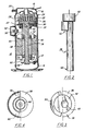
- Fig. 1 is a longitudinal sectional view of a scroll-type compressor according to one preferred embodiment of this invention.
- Fig. 2 is a side elevation of a rotor crankshaft according to this embodiment of the invention.
- Fig. 3 is a top plan view of the shaft and rotor assembly.
- Fig. 4 is a bottom plan view of the shaft and rotor assembly.
- Fig. 1 shows a scroll compressor assembly 10 of the type which can be used with a refrigeration or air conditioning system.
- the assembly 10 has a generally cylindrical shell or housing 12, which is closed off at its lower end with a lower cap 14 and is closed off at its upper end with an upper cap 16.
- a pressure dome 18 in the cap 16 holds gas that is compressed in the compressor and conducts it to a high pressure outlet 20 from the center of a fixed scroll 22 that is rigidly mounted within the housing 12.
- the fixed scroll 22 has an involute or spiral wrap 24.
- the assembly 10 also has an orbiting scroll 26 with a similar involute wrap 28 that interleaves with the wrap 24 of the fixed scroll 22.
- a male stub 30 depends from the orbiting scroll 26 at the center or axis thereof.
- An anti-rotation device such as an Oldham's ring 32 is associated with the orbiting scroll 26 to prevent rotation of the orbiting scroll, but while permitting it to revolve without rotation around the axis of the fixed scroll 22.
- a crankcase 34 and bearing are situated with the housing 12 just below the orbiting scroll 26.
- a one-piece crankshaft assembly 36 as shown in Fig. 2 can be unitarily cast of ductile iron or an equivalent material.
- a generally cylindrical electrical rotor 38 is press fit onto the shaft 36 and fits into a cylindrical passage in an electric motor stator armature 40 that is affixed in place onto the interior of the housing 12.
- the passage has a predetermined radius, so that a small gap remains between the rotor 38 and the stator 40.
- the rotor 38 and stator 40 constitute an electric motor for the compressor assembly 10.
- a generally cylindrical crank 42 which is unitarily formed on an upper end of the shaft 36 is journaled within the crankcase 34. At the top surface of this crank 42 there is an offset female receptacle or socket 48.
- the socket 48 serves as a receptacle for the make stub 30 of the orbiting scroll 26.
- a counterweight 50 is also unitarily formed on the shaft 36, in this embodiment adjacent crank 42.
- the counterweight 50 is arcuate in form, in the shape of a segment of a cylinder, and here subtending an arc of approximately 160°.
- the counterweight 50 is disposed to the side opposite the radial position of the offset of the orbiting scroll 26.
- the counterweight 50 lies at or within the radius of the cylindrical passage in the stator 40. This feature permits the crank and rotor assembly to be installed from below after the stator 40 has been affixed into the housing 12.
- the counterweight 50 extends axially downwards to the position of an upper ring 52 on the rotor 38. There is also a lower ring 54 on the rotor 38. A generally semi-circular or half-ring rotor counterweight 56 is affixed onto the lower ring 54 in the position radially opposite that of the counterweight 50. Then, a lower bearing 58 journals a lower end 60 of the shaft 36.
- FIG. 1 Also shown in Fig. 1 is an electrical connector 62 which connects electrical power to the stator 40.
- this unitary crankshaft 36, with integral crank 42 and counterweight 50 not only provides simplicity of assembly, but increases the reliability of the compressor.
- the counterweight 50 is rigidly and permanently situated on the crankshaft 36, and is situated as close as possible to the axial position of the orbiting scroll 26, thereby providing optimal balancing. Placing the counterweight 50 at the upper end of the crankshaft 36, rather than directly on the rotor 38, minimizes the effect of destructive transient torques, and thereby further increases the reliability of the compressor 10.
Landscapes
- Engineering & Computer Science (AREA)
- Mechanical Engineering (AREA)
- General Engineering & Computer Science (AREA)
- Applications Or Details Of Rotary Compressors (AREA)
- Rotary Pumps (AREA)
- Compressor (AREA)
- Shafts, Cranks, Connecting Bars, And Related Bearings (AREA)
Claims (5)
- Spiralkompressor (10) des Typs, der einen Mantel (12) aufweist, welcher eine feststehende Spirale (22) und eine umlaufende Spirale (26) enthält, die versetzt von der Achse der feststehenden Spirale (22) angeordnet ist, um sich um die Achse der feststehenden Spirale (22) zu drehen,
eine Drehungsverhinderungseinrichtung (32) zum Festhalten der Umlaufspirale (26) gegen Drehung, die ihr aber gestattet, in einer Umlaufbewegung umzulaufen,
einen Elektromotorständer (40), der in dem Mantel (12) angeordnet ist und einen zylindrischen Durchlaß mit einem vorbestimmten Radius,
eine Elektromotorläuferbaugruppe (38), die in dem Mantel (12) drehbar gelagert ist, zum Antreiben der Umlaufspirale (26) auf ihrer Umlaufbewegung,
wobei die Läuferbaugruppe (38) eine Kurbelwellenbaugruppe (36, 42, 50) und einen insgesamt zylindrischen Läufer (38) umfaßt, der auf der Kurbelwellenbaugruppe befestigt und in den insgesamt zylindrischen Durchlaß des Ständers (40) eingepaßt ist, die Kurbelwellenbaugruppe (36, 42, 50) eine langgestreckte Welle (36), eine Kurbel (42), die an einem oberen Ende der Welle (36) angeordnet und in einem Zapfenlagergehäuse (34) unter der umlaufenden Spirale (26) drehbar gelagert ist, sowie ein Gegengewicht (50) hat, welches die achsenversetzte Umlaufbewegung der Umlaufspirale (12) ausgleicht, wobei das Gegengewicht (50) unmittelbar neben der Position der Kurbel (42) gebildet ist,
wobei die Läuferbaugruppe (38) das einzige Gebilde innerhalb des vorbestimmten Radius zwischen dem Motorständer (40) und dem Zapfenlagergehäuseteil (34) ist,
die Kurbel (42) eine exzentrische Befestigungseinrichtung (48) zum Antreiben der Umlaufspirale (26) und
zum Erzeugen der Umlaufbewegung derselben hat und ein unteres Lager (58) zum drehbaren Lagern eines unteren Endes der Welle (36) dient, wobei das untere Lager (58) unter der Läuferbaugruppe (38) angeordnet ist,
dadurch gekennzeichnet, daß das Gegengewicht (50) einstückig mit der Welle (36) ausgebildet und unter der Kurbel (42) angeordnet ist, wobei der Gasauslaßweg separat von der Kurbel (42) angeordnet ist und wobei die radiale Ausdehnung des Gegengewichts (50) auf der Welle (36) nicht größer als der vorbestimmte Radius ist, so daß die Welle mit dem Gegengewicht beim Einbau durch den Ständerdurchlaß hindurchgeführt werden kann. - Spiralkompressor nach Anspruch 1, dadurch gekennzeichnet, daß die Welle (36) und das Gegengewicht (50) einstückig aus Eisen gegossen sind.
- Spiralkompressor nach Anspruch 1, dadurch gekennzeichnet, daß die Kurbel (42) ein insgesamt zylindrisches Kurbelteil ist, das einstückig mit dem oberen Ende der Welle (36) ausgebildet ist.
- Spiralkompressor nach Anspruch 1, dadurch gekennzeichnet, daß das Gegengewicht (50) ein insgesamt zylindrisches Segment ist und sich über einen Bogen von etwa 160° erstreckt.
- Spiralkompressor nach Anspruch 1, dadurch gekennzeichnet, daß er weiter ein Läufergegengewicht (56) aufweist, das an dem Läufer (38) an einem Ende befestigt ist, das von dem erstgenannten Gegengewicht (50) entfernt und radial entgegengesetzt zu der Position des erstgenannten Gegengewichts (50) angeordnet ist.
Applications Claiming Priority (2)
| Application Number | Priority Date | Filing Date | Title |
|---|---|---|---|
| US445552 | 1989-12-04 | ||
| US07/445,552 US5007810A (en) | 1989-12-04 | 1989-12-04 | Scroll compressor with unitary crankshaft, upper bearing and counterweight |
Publications (2)
| Publication Number | Publication Date |
|---|---|
| EP0432084A1 EP0432084A1 (de) | 1991-06-12 |
| EP0432084B1 true EP0432084B1 (de) | 1994-02-16 |
Family
ID=23769365
Family Applications (1)
| Application Number | Title | Priority Date | Filing Date |
|---|---|---|---|
| EP90630195A Expired - Lifetime EP0432084B1 (de) | 1989-12-04 | 1990-11-15 | Spiralverdichterkurbelwelle mit Lager und Gegengewicht |
Country Status (9)
| Country | Link |
|---|---|
| US (1) | US5007810A (de) |
| EP (1) | EP0432084B1 (de) |
| JP (1) | JPH03182694A (de) |
| KR (1) | KR910012541A (de) |
| BR (1) | BR9006092A (de) |
| DE (1) | DE69006696T2 (de) |
| ES (1) | ES2049451T3 (de) |
| MX (1) | MX168661B (de) |
| MY (1) | MY105405A (de) |
Cited By (1)
| Publication number | Priority date | Publication date | Assignee | Title |
|---|---|---|---|---|
| US7861541B2 (en) | 2004-07-13 | 2011-01-04 | Tiax Llc | System and method of refrigeration |
Families Citing this family (11)
| Publication number | Priority date | Publication date | Assignee | Title |
|---|---|---|---|---|
| DE4139781A1 (de) * | 1991-12-03 | 1993-06-09 | Alfred Teves Gmbh, 6000 Frankfurt, De | Kolbenpumpe |
| US5267844A (en) * | 1992-04-13 | 1993-12-07 | Copeland Corporation | Compressor assembly with staked shell |
| CN1085789C (zh) * | 1993-11-15 | 2002-05-29 | 科普兰公司 | 采用有桩外壳的压缩机装置 |
| US5476369A (en) * | 1994-07-25 | 1995-12-19 | Tecumseh Products Company | Rotor counterweight insert apparatus |
| JPH08326676A (ja) * | 1995-06-05 | 1996-12-10 | Matsushita Electric Ind Co Ltd | 冷凍機用圧縮機 |
| JPH1089003A (ja) * | 1996-09-20 | 1998-04-07 | Hitachi Ltd | 容積型流体機械 |
| JP3614694B2 (ja) * | 1999-01-22 | 2005-01-26 | 松下電器産業株式会社 | 電動機直結駆動軸の両持ち軸受構造の与圧方法および装置とそれらを用いた密閉型圧縮機 |
| TW531592B (en) * | 1999-09-09 | 2003-05-11 | Sanyo Electric Co | Multiple stage high pressure compressor |
| US6345966B1 (en) * | 2000-06-30 | 2002-02-12 | Scroll Technologies | Scroll compressor with dampening bushing |
| JP4696153B2 (ja) * | 2008-12-15 | 2011-06-08 | 日立アプライアンス株式会社 | 回転型圧縮機 |
| JP6749183B2 (ja) * | 2016-08-31 | 2020-09-02 | ダイキン工業株式会社 | スクロール圧縮機 |
Family Cites Families (7)
| Publication number | Priority date | Publication date | Assignee | Title |
|---|---|---|---|---|
| US3874827A (en) * | 1973-10-23 | 1975-04-01 | Niels O Young | Positive displacement scroll apparatus with axially radially compliant scroll member |
| JPS59224493A (ja) * | 1983-06-03 | 1984-12-17 | Mitsubishi Electric Corp | スクロ−ル圧縮機 |
| JPS60224986A (ja) * | 1984-04-21 | 1985-11-09 | Daikin Ind Ltd | スクロ−ル形流体機械 |
| JPS60243301A (ja) * | 1984-05-18 | 1985-12-03 | Mitsubishi Electric Corp | スクロール流体機械及びその流体機械の組立て方法 |
| JPS618487A (ja) * | 1984-06-21 | 1986-01-16 | Toshiba Corp | スクロ−ル型圧縮装置 |
| KR890000052B1 (ko) * | 1985-05-16 | 1989-03-06 | 미쓰비시전기 주식회사 | 스크롤 유체기계 |
| JPH01182586A (ja) * | 1988-01-14 | 1989-07-20 | Sanden Corp | 密閉型スクロール圧縮機 |
-
1989
- 1989-12-04 US US07/445,552 patent/US5007810A/en not_active Expired - Fee Related
-
1990
- 1990-11-15 DE DE69006696T patent/DE69006696T2/de not_active Expired - Fee Related
- 1990-11-15 ES ES90630195T patent/ES2049451T3/es not_active Expired - Lifetime
- 1990-11-15 EP EP90630195A patent/EP0432084B1/de not_active Expired - Lifetime
- 1990-11-23 MY MYPI90002071A patent/MY105405A/en unknown
- 1990-11-29 JP JP2333414A patent/JPH03182694A/ja active Pending
- 1990-11-30 BR BR909006092A patent/BR9006092A/pt not_active IP Right Cessation
- 1990-12-03 MX MX023570A patent/MX168661B/es unknown
- 1990-12-03 KR KR1019900019832A patent/KR910012541A/ko not_active Ceased
Cited By (1)
| Publication number | Priority date | Publication date | Assignee | Title |
|---|---|---|---|---|
| US7861541B2 (en) | 2004-07-13 | 2011-01-04 | Tiax Llc | System and method of refrigeration |
Also Published As
| Publication number | Publication date |
|---|---|
| DE69006696D1 (de) | 1994-03-24 |
| JPH03182694A (ja) | 1991-08-08 |
| BR9006092A (pt) | 1991-09-24 |
| KR910012541A (ko) | 1991-08-08 |
| ES2049451T3 (es) | 1994-04-16 |
| DE69006696T2 (de) | 1994-06-23 |
| MY105405A (en) | 1994-09-30 |
| EP0432084A1 (de) | 1991-06-12 |
| MX168661B (es) | 1993-06-02 |
| US5007810A (en) | 1991-04-16 |
Similar Documents
| Publication | Publication Date | Title |
|---|---|---|
| EP1026402B1 (de) | Spiralverdichter | |
| EP0479412B1 (de) | Oldham's Kupplung für Spiralverdichter | |
| EP0855511B1 (de) | Abstandhalter für eine hermetische Motor-Verdichter-Einheit | |
| EP0430854B1 (de) | Mehrteilige Exzenterwelle | |
| EP0432083B1 (de) | Spiralverdichter und Montageverfahren dafür | |
| EP0432084B1 (de) | Spiralverdichterkurbelwelle mit Lager und Gegengewicht | |
| EP0066457B1 (de) | Mechanismus der Antriebslagerung für eine umlaufende Spirale einer Verdrängermaschine vom Spiraltyp | |
| US4730998A (en) | Scroll-type apparatus having a pivoting main journal bearing | |
| JPS62142882A (ja) | スクロ−ル圧縮機 | |
| EP1122438B1 (de) | Oldham's Kupplung für Spiralverdichter | |
| US4512729A (en) | Drive bearing device for a fluid displacement apparatus | |
| US5242282A (en) | Scroll compressor with a driving pin between scrolls and a sliding shaft bearing | |
| JPH04295194A (ja) | スクロール圧縮機の給油装置 | |
| EP0283045B1 (de) | Spiralkompresseur | |
| JP4263323B2 (ja) | スクロール流体機械 | |
| JP2754037B2 (ja) | スクロール圧縮機 | |
| JP2925654B2 (ja) | スクロール圧縮機 | |
| JPH077590Y2 (ja) | スクロ−ル圧縮機 | |
| JP2559430B2 (ja) | 密閉形スクロール圧縮機 | |
| JP2604325B2 (ja) | スクロール圧縮機 | |
| JPS63309794A (ja) | スクロ−ル圧縮機 | |
| JPH0794824B2 (ja) | スクロール圧縮機 | |
| JPH0573284U (ja) | スクロール型圧縮機 | |
| JPS63309793A (ja) | スクロ−ル圧縮機 | |
| JPH06159268A (ja) | スクロール圧縮機 |
Legal Events
| Date | Code | Title | Description |
|---|---|---|---|
| PUAI | Public reference made under article 153(3) epc to a published international application that has entered the european phase |
Free format text: ORIGINAL CODE: 0009012 |
|
| AK | Designated contracting states |
Kind code of ref document: A1 Designated state(s): BE DE DK ES FR IT |
|
| 17P | Request for examination filed |
Effective date: 19910731 |
|
| 17Q | First examination report despatched |
Effective date: 19910920 |
|
| ITF | It: translation for a ep patent filed | ||
| GRAA | (expected) grant |
Free format text: ORIGINAL CODE: 0009210 |
|
| AK | Designated contracting states |
Kind code of ref document: B1 Designated state(s): BE DE DK ES FR IT |
|
| REF | Corresponds to: |
Ref document number: 69006696 Country of ref document: DE Date of ref document: 19940324 |
|
| ET | Fr: translation filed | ||
| REG | Reference to a national code |
Ref country code: ES Ref legal event code: FG2A Ref document number: 2049451 Country of ref document: ES Kind code of ref document: T3 |
|
| ITF | It: translation for a ep patent filed | ||
| PG25 | Lapsed in a contracting state [announced via postgrant information from national office to epo] |
Ref country code: DK Effective date: 19941115 |
|
| PG25 | Lapsed in a contracting state [announced via postgrant information from national office to epo] |
Ref country code: BE Effective date: 19941130 |
|
| PLBE | No opposition filed within time limit |
Free format text: ORIGINAL CODE: 0009261 |
|
| STAA | Information on the status of an ep patent application or granted ep patent |
Free format text: STATUS: NO OPPOSITION FILED WITHIN TIME LIMIT |
|
| 26N | No opposition filed | ||
| BERE | Be: lapsed |
Owner name: CARRIER CORP. Effective date: 19941130 |
|
| PGFP | Annual fee paid to national office [announced via postgrant information from national office to epo] |
Ref country code: FR Payment date: 19951009 Year of fee payment: 6 |
|
| PGFP | Annual fee paid to national office [announced via postgrant information from national office to epo] |
Ref country code: DE Payment date: 19951023 Year of fee payment: 6 |
|
| PGFP | Annual fee paid to national office [announced via postgrant information from national office to epo] |
Ref country code: ES Payment date: 19951108 Year of fee payment: 6 |
|
| PG25 | Lapsed in a contracting state [announced via postgrant information from national office to epo] |
Ref country code: ES Free format text: LAPSE BECAUSE OF NON-PAYMENT OF DUE FEES Effective date: 19961116 |
|
| PG25 | Lapsed in a contracting state [announced via postgrant information from national office to epo] |
Ref country code: FR Effective date: 19970731 |
|
| PG25 | Lapsed in a contracting state [announced via postgrant information from national office to epo] |
Ref country code: DE Effective date: 19970801 |
|
| REG | Reference to a national code |
Ref country code: FR Ref legal event code: ST |
|
| REG | Reference to a national code |
Ref country code: ES Ref legal event code: FD2A Effective date: 19971213 |
|
| PG25 | Lapsed in a contracting state [announced via postgrant information from national office to epo] |
Ref country code: IT Free format text: LAPSE BECAUSE OF NON-PAYMENT OF DUE FEES Effective date: 20051115 |