EP0432476B1 - Elektrophotographisches Gerät mit mehreren Betriebsgeschwindigkeiten - Google Patents
Elektrophotographisches Gerät mit mehreren Betriebsgeschwindigkeiten Download PDFInfo
- Publication number
- EP0432476B1 EP0432476B1 EP90121646A EP90121646A EP0432476B1 EP 0432476 B1 EP0432476 B1 EP 0432476B1 EP 90121646 A EP90121646 A EP 90121646A EP 90121646 A EP90121646 A EP 90121646A EP 0432476 B1 EP0432476 B1 EP 0432476B1
- Authority
- EP
- European Patent Office
- Prior art keywords
- speed
- scanning
- image
- image forming
- mode
- Prior art date
- Legal status (The legal status is an assumption and is not a legal conclusion. Google has not performed a legal analysis and makes no representation as to the accuracy of the status listed.)
- Expired - Lifetime
Links
- 241001269238 Data Species 0.000 claims 1
- 239000002245 particle Substances 0.000 description 9
- 238000010586 diagram Methods 0.000 description 4
- 238000000034 method Methods 0.000 description 3
- 230000003247 decreasing effect Effects 0.000 description 2
- 230000002441 reversible effect Effects 0.000 description 2
- 206010034972 Photosensitivity reaction Diseases 0.000 description 1
- 230000003213 activating effect Effects 0.000 description 1
- 230000000712 assembly Effects 0.000 description 1
- 238000000429 assembly Methods 0.000 description 1
- 230000015556 catabolic process Effects 0.000 description 1
- 238000006731 degradation reaction Methods 0.000 description 1
- 230000000694 effects Effects 0.000 description 1
- 239000011521 glass Substances 0.000 description 1
- 230000036211 photosensitivity Effects 0.000 description 1
- 230000000717 retained effect Effects 0.000 description 1
- 230000002123 temporal effect Effects 0.000 description 1
Images


Classifications
-
- G—PHYSICS
- G03—PHOTOGRAPHY; CINEMATOGRAPHY; ANALOGOUS TECHNIQUES USING WAVES OTHER THAN OPTICAL WAVES; ELECTROGRAPHY; HOLOGRAPHY
- G03G—ELECTROGRAPHY; ELECTROPHOTOGRAPHY; MAGNETOGRAPHY
- G03G15/00—Apparatus for electrographic processes using a charge pattern
- G03G15/50—Machine control of apparatus for electrographic processes using a charge pattern, e.g. regulating differents parts of the machine, multimode copiers, microprocessor control
- G03G15/5008—Driving control for rotary photosensitive medium, e.g. speed control, stop position control
-
- G—PHYSICS
- G03—PHOTOGRAPHY; CINEMATOGRAPHY; ANALOGOUS TECHNIQUES USING WAVES OTHER THAN OPTICAL WAVES; ELECTROGRAPHY; HOLOGRAPHY
- G03G—ELECTROGRAPHY; ELECTROPHOTOGRAPHY; MAGNETOGRAPHY
- G03G15/00—Apparatus for electrographic processes using a charge pattern
- G03G15/22—Apparatus for electrographic processes using a charge pattern involving the combination of more than one step according to groups G03G13/02 - G03G13/20
- G03G15/28—Apparatus for electrographic processes using a charge pattern involving the combination of more than one step according to groups G03G13/02 - G03G13/20 in which projection is obtained by line scanning
- G03G15/30—Apparatus for electrographic processes using a charge pattern involving the combination of more than one step according to groups G03G13/02 - G03G13/20 in which projection is obtained by line scanning in which projection is formed on a drum
- G03G15/305—Apparatus for electrographic processes using a charge pattern involving the combination of more than one step according to groups G03G13/02 - G03G13/20 in which projection is obtained by line scanning in which projection is formed on a drum with special means to synchronize the scanning optic to the operation of other parts of the machine, e.g. photoreceptor, copy paper
Definitions
- the present invention relates to an electrophotographic apparatus capable of optically scanning and duplicating an original document (e.g., "photocopier").
- the present invention relates to an electrophotographic copying apparatus having substantially increased copying speed and copy output, with minimal increase in electrostatic toner consumption, and with minimal degradation in copy quality.
- Electromechanical devices capable of electrophotographically duplicating printed documents are well known in the art.
- Such a device comprises two basic functional assemblies: an image generator assembly and an image transfer assembly.
- the image generator assembly typically consists of an electromechanical scanning assembly containing an electrical lamp and a mirror. This assembly scans the original document illuminating it with the electrical lamp. Light reflected from the original document, representative of the image thereon, is reflected via the mirror to the image transfer assembly. By scanning the full width and length of the original document, a full image of the document as contained in the reflected light is transmitted via the mirror to the image transfer assembly.
- the image transfer assembly contains a cylindrical drum having a photosensitive outer surface which is electrostatically charged by an electrostatic generator.
- the reflected light containing the image information of the original document received from the image generator assembly is used to expose the outer surface of this photosensitive drum as it rotates. This causes a latent electrostatic image to form on the outer surface of the drum which corresponds to and is the negative of the original document image.
- Electrostatic toner particles are then applied to the electrostaticaiiy charged surface of the drum. Black image areas, i.e., areas of the electrostatic image corresponding to areas of the original document containing image information, attract and retain the electrostatic toner particles.
- White image areas i.e., areas of the latent electrostatic image corresponding to areas of the original document containing no image information, do not attract and therefore do not retain any electrostatic toner particles.
- the rotating electrostatically charged surface of the drum now containing areas retaining electrostatic toner particles, is brought into physical contact with the surface of a sheet of paper moving with a linear velocity substantially equal to the tangential velocity of the rotating drum.
- an electrostatic charge opposite in potential to that originally applied to the outer surface of the rotating drum is generated at and applied to the opposite surface of the paper. This opposite electrostatic charge attracts the electrostatic toner particles, drawing them away from the outer surface of the rotating drum into the surface of the paper.
- the paper now having electrostatic toner particles impressed thereon and forming an image duplicating that of the original document, then passes through a series of heated rollers. This heat and pressure from the rollers causes the electrostatic toner particles to permanently bond to the surface of the paper. Thus, a substantially identical copy of an original document is created.
- Implicit in this basic photocopying process is the requirement that the tangential speed of the outer surface of the rotating photosensitive drum, and therefore its rotational speed, corresponds to the speed of the scanning assembly scanning the original document. With proper correspondence of these speeds, the electrostatic image formed on the photosensitive drum and therefore transferred to the paper will be a substantially true copy of the original document, i.e., 1:1 original-to-copy image correspondence in both dimensions.
- Document US-A-4,411,514 discloses a photocopying apparatus which provides for varying the rotational speed of the rotating photosensitive drum relative to the linear speed of the scanning assembly, thereby allowing magnified or reduced photosensitivity. According to the teachings of US-A-4,411,514, as the rotational speed of the rotating photosensitive drum is increased or decreased, the quantities of electrostatic charge and electrostatic toner applications are increased or decreased proportionally, respectively. Thus, as the rotational speed of the rotating photosensitive drum varies, the copy image quality remains substantially consistent.
- the present invention provides an image forming apparatus as specified in claim 1.
- the present invention provides a multiple speed electrophotographic copying machine.
- the speeds of the scanning assembly and rotating photosensitive drum may both be selectively increased together so as to increase the copy rate, while maintaining the same copy scaling (e.g., 1:1 with no original-to-copy magnification/reduction).
- the speeds of the scanning assembly and rotating photosensitive drum may be selectively increased without a concomitant increase in applications of either the electrostatic change or electrostatic toner.
- the multiple speed electrophotographic copying machine of the present invention provides a user-operated speed selector whereby the user may select between a "standard” (high copy quality) and a “draft" (faster and pooere-but adequate-copy quality) mode of operation.
- a "standard” high copy quality
- a "draft" faster and pooere-but adequate-copy quality
- the scanning assembly and rotating photosensitive drum operate at their nominal design speeds with standard applications of electrostatic charge and toner, producing high quality copies.
- draft mode the scanning assembly and rotating photosensitive drum operate at increased speeds but without increased applications of electrostatic charge and toner, producing faster and poorer, but adequate, quality copies.
- the multiple speed electrophotographic copying machine of the present invention further provides a means by which the user may, while draft mode, select the quality of the copies. While in draft mode, the user may selectively vary the copying speed (i.e., the speeds of the scanning assembly and rotating photosensitive drum) which, due to the constant application rates of electrostatic charge and toner, determines the resulting copy quality. Thus, the user may selectively maximize copy speed while minimizing wasteful applications of electrostatic charge and toner.
- Figure 1 illustrates the basic components used in an electrophotographic copying machine 10. These components include: a main motor 12 which drives the transport belt 14, fuser rollers 16, 18 and photosensitive drum 20; a feed motor 22 which drives a feed roller 24; an alignment motor 26 which drives alignment roller 28, 30; a scanning motor 32 which drives scanning lamp 34 and lamp reflector 36, a scanning mirror 38 and two scanning image reflectors 40, 42, all of which are mechanically coupled to a scanning transport 44 which is driven along a scanning guide 46; a lens unit 47, two fixed image reflectors 48, 50 and a fixed focusing mirror 52; an electrostatic toner applicator 54; an electrostatic generator 56; an electrostatic transfer charger 58; and a residual toner remover 72.
- a main motor 12 which drives the transport belt 14, fuser rollers 16, 18 and photosensitive drum 20
- a feed motor 22 which drives a feed roller 24
- an alignment motor 26 which drives alignment roller 28, 30
- a scanning motor 32 which drives scanning lamp 34 and lamp reflector 36, a scanning mirror 38
- the scanning lamp 34 illuminates the face of an original document 60 lying on a glass panel 62 which serves as a support surface therefore.
- the illuminated image is reflected onto the scanning mirror 38 and image reflectors 40, 42 along their respective angles of incidence and reflection.
- the image then passes through the lens unit 47 and is reflected onto the fixed image reflectors 48, 50 and focusing mirror 52 along their respective angles of incidence and reflection.
- the focusing mirror 52 then focuses the reflected image onto the surface of the rotating photosensitive drum 20.
- the photosensitive drum 20 rotates with a tangential speed substantially equal to the linear speed of the scanning transport 44, for 1:1 copying (i.e., no magnification or reduction).
- the illuminated and reflected image of the document 60 is projected onto the outer surface of the photosensitive drum 20.
- toner As the surface of the drum 20 rotates past the electrostatic toner applicator 54, toner is applied thereto.
- This toner which is negatively charged, is attracted to and adheres to those areas of the outer surface of the rotating drum 20 which, corresponding to black areas on the original document 60, have retained their positive electrostatic charge.
- a blank sheet of paper 64 withdrawn from a paper tray 66 by the feed roller 24, is aligned beneath the drum 20 by the alignment rollers 28, 30.
- the leading edge of this paper 64 is advanced so as to come into contact with the drum 20 at the point where the reflected image focused onto the drum 20 coincides with the leading edge of the original document 60.
- the drum 20 continues to rotate, causing its toner laden surface to progressively come into contact with the blank paper 64.
- a positive electrostatic charge is applied to the opposite side of the paper 64 by the transfer charger 58. This positive charge attracts substantially all of the negatively charged toner particles, causing them to become embedded in the top surface of the paper 64.
- the originally blank paper 64 becomes a photocopy 68 of the original document 60.
- the emerging photocopy 68 is transported by the transport belt 14 to the fuser rollers 16, 18.
- the fuser rollers 16, 18 apply heat and pressure to the copy 68 which softens the toner particles and presses them into the paper's surface, bonding them thereto.
- the photocopy 68 is then ejected and placed into a receiving tray 70.
- the drum 20 continues to rotate, its surface passing a residual toner remover 72.
- the residual toner remover 72 removes residual toner which was not attracted to and embedded in the surface of the paper 64, but instead remained on the surface of the drum 20.
- Such residual toner removers 72 are well known in the art and may comprise a plastic wiper blade or rotating soft fur brushes.
- the basic photocopy apparatus and process remain the same.
- the electrophotographic copying machine of the present invention provides multiple copying speeds, e.g., "standard” and “draft” modes.
- a user operated speed selector allows the photocopy machine user to select a draft mode, selectively accelerating the speed of the overall photocopying operation, without changing the copy scaling (e.g., 1:1 with no original-to-copy magnification/reduction).
- the reproduced image quality may become somewhat degraded, in many (if not most) cases it is adequate and the number of photocopies which may be produced per unit time may be easily and greatly increased.
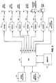
- FIG. 2 illustrates in simplified, functional block diagram form the major electrical components and interconnections for the electrophotographic copying machine of the present invention.
- These major components include: a central processing unit (“CPU") 110; an electronic memory 112; a speed selector 114 (e.g., an electrical switch); a speed indicator 116 (e.g., an indicator lamp or light emitting diode); a main motor 12 and driver 118 therefor; a feed motor 22 and driver 120 therefor; a scanning motor 32 and driver 122 therefor; an alignment motor 26 and driver 124 therefor; an electrostatic generator 56 and driver 126 therefor; a scanning lamp 34 and driver 128 therefor; and a toner applicator 54.
- CPU central processing unit
- a speed selector 114 e.g., an electrical switch
- a speed indicator 116 e.g., an indicator lamp or light emitting diode
- main motor 12 and driver 118 therefor
- feed motor 22 and driver 120 therefor
- the CPU 110 supplies the requisite control signals 130-141 necessary to operate the photocopying machine.
- the CPU 110 uses the electronic memory 112 for storing instructions and data necessary to its operation.
- a speed selector 114 is available so that the user may selectively instruct the CPU 110 regarding the speed at which the photocopying machine is to be operated.
- a speed indicator 116 is also provided as a form of feedback to the user to indicate the speed at which the photocopying machine is being operated.
- the appropriate control signals 130-140 will be sent to the drivers 118-128 for the major components 12, 22, 32, 26, 56, 34 of the photocopying machine 10.
- Drivers for these types of components are well known in the art and are capable of accepting the digital control signals 130-140 from the CPU 110 and generating the appropriate signals 142-152 to directly drive their associated components.
- FIG. 3A showns in timing diagram form the typical initial temporal status and sequence of the direct control signals 142-152 during standard operation at standard speed when copying first begins.
- Elapsed time in seconds from the beginning of Stage 1 is indicated along the bottom of Figure 3A, while the numbers along the top indicate discrete "stages" of the photocopying operation for the first and second copies.
- Stage 0 is the 1-second time interval between when the user first instructs the photocopying machine 10 to begin and when the actual photocopying operation (as described above) begins.
- Figure 3A illustrates with particularity the timing sequence of the photocopying operation which was described in general above for Figure 1.
- the feed motor 22 is on and feeding a sheet of paper 64 during stages 1-3. It is off during states 4-7, and turned back on at stage 8.
- the scanning lamp 34 is turned on at stage 2 in preparation for illuminating and scanning the original document 60. It remains on until the end of stage 6, when scanning is complete.
- the electrostatic generator 56 is turned on at stage 3, imparting its electrostatic charges to the photosensitive drum 20. It is turned off after stage 5 when scanning is complete.
- the scanning motor 32 is turned on at stage 4, causing the scanning components 34, 36, 38, 40, 42 to scan the length of the document 60 in the forward direction. Scanning is complete after stage 5 and the scanning motor 32 is turned off. At stage 7, the scanning motor 32 is turned on in the reverse direction to return the scanning transport 44 to its original location. This reverse scanning is complete by stage 10 and the scanning motor 32 is turned off.
- the alignment motor 26 is turned on for aligning the blank paper 64 with the rotating photosensitive drum 20. Alignment is complete and the alignment motor or 26 is turned off after stage 8.
- Figure 3B illustrates the timing sequence for the control signals 142-152 for a preferred embodiment of the photocopy machine of the present invention operating at an accelerated copying speed (e.g., draft mode).
- the basic timing sequence is no different from that as shown in Figure 3A and discussed above. However, although just as many stages (“A-stages" in this case) are involved, the time durations of several stages are reduced. In addition, the rate of application by the toner applicator 54 is not changed from that used in the standard mode (as described above for Figure 3A).
- the "on" times for the scanning lamp 34, electrostatic generator 56, scanning motor 32 and alignment motor 26 are shorter. Although these "on" times are shorter, a full copying cycle is completed since the appropriate motors are operated at increased rates of speed. Furthermore, although the electrostatic generator 56 is on for a shorter period of time, the amount of charge per unit time applied by the generator 56 remains the same as in the standard mode.
- the main motor 12 runs faster so as to rotate the photosensitive drum 20 faster.
- the scanning motor 32 is run faster so as to move the scanning transport 44 faster.
- the alignment motor 26 is run faster so as to more quickly align the incoming blank paper 64 with the proper location on the outer surface of the rotating photosensitive drum 20.
- the scanning motor 32 and alignment motor 26 are pulse motors. By controlling the width and/or number of voltage pulses applied to the motors, the speed of the motors is controlled.
- voltage pulses comprising the control signals 146, 148 to the scanning motor 32 and alignment motor 26 can be varied in width and/or frequency. This is quite easily accomplished by providing corresponding pulse variations in the control signals 134, 136 applied to the drivers 122, 124 responsible for driving the scanning motor 32 and alignment motor 26.
- such pulse variations may be provided for by storing the appropriate instructions and/or data within the electronic memory 112 for access and use by the CPU 110 when an accelerated speed has been selected by the user through the speed selector 114.
- the CPU 110 Upon selection of an accelerated speed, the CPU 110 simply goes to the appropriate memory locations within the electronic memory 112 and uses the instructions and/or data stored therein to generate the appropriate control signals 134, 136.
- Figure 4 illustrates how the electronic memory 112 may be organized to store instructions and/or data appropriate for use by the CPU 110 in controlling the various component drivers 118-128.
- the individual memory locations are used to store instructions and/or data necessary for the CPU 110 to generate the appropriate control signals 130-141 so as to operate the components 12, 22, 32, 26, 56, 34, 54 appropriately and in the proper timing sequences, as shown in Figures 3A and 3B.
- one memory location may be used to hold binary data representing a flag ("A-Flag") indicating that the accelerated speed mode has been selected by the user via the speed selector 114.
- Other memory locations may be used to store binary data representing the instructions and/or data needed by the CPU 110 to generate the appropriate control signals 130-141 during each stage of operation (see discussion above for Figure 3A).
- Still other memory locations may be used to store binary data representing the instructions and/or data needed by the CPU 110 for generating the appropriate control signals 130-141 for each of the stages of operation in the accelerated speed mode (see discussion above regarding "A-Stages" for Figure 3B).
- a preferred embodiment of the present invention provides for the use of a main motor driver 118 capable of providing a drive signal 142 providing selectably variable voltage and/or current to the armature of the main motor 12.
- the speed selector 114 may be a switch by which the user may select between a standard mode having a single fixed reproduction speed and a plurality of draft modes, each having a different reproduction speed.
- the different draft modes differ in their rates of speeds of the main motor 12, scanning motor 32 and alignment motor 26.
- Each draft mode is selected by the user according to the desired reproduction speed.
- the application rates of the electrostatic generator 56 and toner applicator 54 remain substantially constant.
- the user may select the reproduction speed, but with an inverse effect on the level of reproduction quality.
- the reproduction speed may be selected by the user via the speed selector 114 at the beginning of the reproduction operation, i.e., before any copies have been made or at any point in the reproduction operation.
- the respective speeds of the main motor 12, scanning motor 32 and alignment motor 26 may be selectively increased when a higher photocopy rate is desired, without affecting the copy scaling.
- the photocopy rate may be maximized while minimizing wasteful electrostatic charge generation and electrostatic toner consumption.
Landscapes
- Physics & Mathematics (AREA)
- General Physics & Mathematics (AREA)
- Engineering & Computer Science (AREA)
- Microelectronics & Electronic Packaging (AREA)
- Control Or Security For Electrophotography (AREA)
- Dry Development In Electrophotography (AREA)
Claims (3)
- Ein Abbildungsgerät mit:
Mittel (118, 120) zum Bewegen eines bildtragenden Baugliedes (20) in einer vorher bestimmten Richtung;
Mittel (32, 36, 38, 40, 42) zum Abtasten eines Originalbildes, um ein latentes, dem Originalbild entsprechendes Bild auf dem bildtragenden Bauglied (20) zu schaffen, das durch das Bewegungsmittel (118, 120) bewegt wird; und
Mittel (54) zum Entwickeln des latenten Bildes, indem ein Entwicklungsstoff auf das bildtragende Bauglied (20) aufgetragen wird;
Mittel (114) zum Spezifizieren eines ersten Abbildungsmodus, in welchem das Bewegungsmittel (118, 120) und das Abtastmittel (32, 36, 38, 40, 42) bei einer ersten Geschwindigkeit (S1, P1) gesteuert werden, oder eines zweiten Abbildungsmodus, in welchem das Bewegungsmittel (118, 120) und das Abtastmittel (32, 36, 38, 40, 42) bei einer zweiten Geschwindigkeit (S2, P2), die von der ersten Geschwindigkeit (S1, P1) verschieden ist, gesteuert werden; und
Mittel (110) zum Regeln des Bewegungsmittels (118, 120) und des Abtastmittels (32, 36, 38, 40, 42), um sie bei der Geschwindigkeit zu steuern, welche dem durch das spezifizierende Mittel (114) eingestellten Modus entspricht,
dadurch gekennzeichnet, daß
das Regelungsmittel (110) derart regelt, daß das Entwicklungsmittel (54) eine im wesentlichen konstante Menge des Entwicklungsstoffes pro Zeiteinheit auf das bildtragende Bauglied (20) ungeachtet des Einstellmodus aufträgt, und
das Regelungsmittel ein Umschalten zwischen dem ersten Abbildungsmodus und dem zweiten Abbildungsmodus zu irgendeinem Zeitpunkt einer Abbildungsoperation ermöglicht. - Das Abbildungsgerät nach Anspruch 1, dadurch gekennzeichnet, daß das Regelungsmittel (110) Mittel einschließt zum Speichern von mindestens zwei Geschwindigkeitsdaten, um die Steuerungsgeschwindigkeit des Bewegungsmittels (118, 120) und des Abtastmittels (32, 36, 38, 40, 42) zu bestimmen, die dem durch das spezifizierende Mittel (114) eingestellten Modus entspricht.
- Das Abbildungsgerät nach Anspruch 1, dadurch gekennzeichnet, daß das spezifizierende Mittel (114) einen durch einen Benutzer wählbaren Schalter einschließt, der in einer Position angeordnet ist, die eine Betätigung durch einen Benutzer gestattet.
Applications Claiming Priority (2)
| Application Number | Priority Date | Filing Date | Title |
|---|---|---|---|
| US437940 | 1982-11-01 | ||
| US07/437,940 US5030994A (en) | 1989-11-16 | 1989-11-16 | Electrophotographic apparatus with multiple speed mode |
Publications (3)
| Publication Number | Publication Date |
|---|---|
| EP0432476A2 EP0432476A2 (de) | 1991-06-19 |
| EP0432476A3 EP0432476A3 (en) | 1991-10-09 |
| EP0432476B1 true EP0432476B1 (de) | 1994-07-13 |
Family
ID=23738553
Family Applications (1)
| Application Number | Title | Priority Date | Filing Date |
|---|---|---|---|
| EP90121646A Expired - Lifetime EP0432476B1 (de) | 1989-11-16 | 1990-11-12 | Elektrophotographisches Gerät mit mehreren Betriebsgeschwindigkeiten |
Country Status (6)
| Country | Link |
|---|---|
| US (1) | US5030994A (de) |
| EP (1) | EP0432476B1 (de) |
| JP (1) | JPH03184066A (de) |
| CA (1) | CA2029732C (de) |
| DE (1) | DE69010643T2 (de) |
| MX (1) | MX171624B (de) |
Families Citing this family (10)
| Publication number | Priority date | Publication date | Assignee | Title |
|---|---|---|---|---|
| JPH03282567A (ja) * | 1990-03-30 | 1991-12-12 | Toshiba Corp | 画像形成装置 |
| JP2810813B2 (ja) * | 1991-10-03 | 1998-10-15 | 富士通株式会社 | 印刷制御装置 |
| JPH06121126A (ja) * | 1992-10-02 | 1994-04-28 | Canon Inc | ファクシミリ装置 |
| US5536597A (en) * | 1993-12-17 | 1996-07-16 | Mitsubishi Gas Chemical Company | Lithium secondary battery employing a non-aqueous electrolyte |
| JPH09325431A (ja) * | 1996-06-03 | 1997-12-16 | Mita Ind Co Ltd | 画像形成装置の露光光源制御装置 |
| JP2002062727A (ja) * | 2000-08-16 | 2002-02-28 | Konica Corp | 画像形成装置 |
| JP4330112B2 (ja) | 2002-12-09 | 2009-09-16 | 株式会社リコー | カラー画像形成装置 |
| KR100605744B1 (ko) * | 2004-07-22 | 2006-08-01 | 삼성전자주식회사 | 인쇄속도 제어가 가능한 전자사진방식 화상형성장치 및 그제어방법 |
| JP2008046552A (ja) * | 2006-08-21 | 2008-02-28 | Konica Minolta Business Technologies Inc | 画像形成装置 |
| JP2008052017A (ja) * | 2006-08-24 | 2008-03-06 | Konica Minolta Business Technologies Inc | カラー画像形成装置、画像形成プログラム及びカラー画像形成方法 |
Family Cites Families (6)
| Publication number | Priority date | Publication date | Assignee | Title |
|---|---|---|---|---|
| JPS52117135A (en) * | 1976-03-26 | 1977-10-01 | Toshiba Corp | Electrophotographic copier |
| US4411514A (en) * | 1979-04-24 | 1983-10-25 | Canon Kabushiki Kaisha | Variable magnification electrophotographic copying apparatus |
| US4537495A (en) * | 1983-07-01 | 1985-08-27 | Zerox Corporation | Multispeed development system |
| JPH0767298B2 (ja) * | 1983-10-26 | 1995-07-19 | 株式会社東芝 | 像形成装置の原稿走査制御装置 |
| US4659209A (en) * | 1984-03-02 | 1987-04-21 | Sharp Kabushiki Kaisha | Exposure mode selectro for automatically selecting automatic exposure control mode for electrophotographic copying machine |
| JPS6456471A (en) * | 1987-08-27 | 1989-03-03 | Toshiba Corp | Image recording device |
-
1989
- 1989-11-16 US US07/437,940 patent/US5030994A/en not_active Expired - Lifetime
-
1990
- 1990-11-06 JP JP2300181A patent/JPH03184066A/ja active Pending
- 1990-11-12 MX MX023289A patent/MX171624B/es unknown
- 1990-11-12 EP EP90121646A patent/EP0432476B1/de not_active Expired - Lifetime
- 1990-11-12 DE DE69010643T patent/DE69010643T2/de not_active Expired - Fee Related
- 1990-11-13 CA CA002029732A patent/CA2029732C/en not_active Expired - Fee Related
Also Published As
| Publication number | Publication date |
|---|---|
| US5030994A (en) | 1991-07-09 |
| JPH03184066A (ja) | 1991-08-12 |
| EP0432476A3 (en) | 1991-10-09 |
| DE69010643D1 (de) | 1994-08-18 |
| CA2029732C (en) | 2001-01-30 |
| DE69010643T2 (de) | 1994-11-03 |
| MX171624B (es) | 1993-11-09 |
| CA2029732A1 (en) | 1991-05-17 |
| EP0432476A2 (de) | 1991-06-19 |
Similar Documents
| Publication | Publication Date | Title |
|---|---|---|
| US5619316A (en) | Image forming apparatus | |
| EP0432476B1 (de) | Elektrophotographisches Gerät mit mehreren Betriebsgeschwindigkeiten | |
| GB2282781A (en) | Method of and apparatus for cleaning charge-inducing member | |
| GB2042746A (en) | Multiple Variable Light Source Photographic Printer | |
| US7020405B2 (en) | Image forming device capable of interrupting application of driving signal at a drive unit | |
| EP0245880B1 (de) | Elektrostatisches Kopiergerät mit veränderbarer Vergrösserung | |
| US4678314A (en) | Image forming apparatus | |
| US4420246A (en) | Multiple reproduction apparatus | |
| US5555077A (en) | Printer having an active user interface feature | |
| US5459554A (en) | Image-forming apparatus for forming an image at a plurality of image-forming conditions | |
| US4616922A (en) | Electrophotographic copying apparatus and process | |
| US4891287A (en) | Image editing method | |
| US4652114A (en) | Electrophotographic copying apparatus and process | |
| US4791494A (en) | Multiple variable light source printer | |
| US4111541A (en) | Exposure system for electrostatic reproduction machines | |
| JP3401686B2 (ja) | 画像形成装置 | |
| US5099282A (en) | Variable magnification image forming apparatus | |
| US4657371A (en) | Electrophotographic copying apparatus and process | |
| JPS61183675A (ja) | トナ−濃度制御装置 | |
| JPS62115489A (ja) | カラ−画像形成装置用クリ−ニング装置 | |
| JPS6032067A (ja) | 電子写真複写機 | |
| JP2985234B2 (ja) | 電子写真画像形成装置 | |
| KR910006692B1 (ko) | 복사기의 반복 복사 방법 | |
| JPH0926697A (ja) | 画像形成装置とその画像形成方法 | |
| JPS62194244A (ja) | 複写装置 |
Legal Events
| Date | Code | Title | Description |
|---|---|---|---|
| PUAI | Public reference made under article 153(3) epc to a published international application that has entered the european phase |
Free format text: ORIGINAL CODE: 0009012 |
|
| 17P | Request for examination filed |
Effective date: 19901207 |
|
| AK | Designated contracting states |
Kind code of ref document: A2 Designated state(s): DE FR GB |
|
| PUAL | Search report despatched |
Free format text: ORIGINAL CODE: 0009013 |
|
| AK | Designated contracting states |
Kind code of ref document: A3 Designated state(s): DE FR GB |
|
| 17Q | First examination report despatched |
Effective date: 19921208 |
|
| GRAA | (expected) grant |
Free format text: ORIGINAL CODE: 0009210 |
|
| AK | Designated contracting states |
Kind code of ref document: B1 Designated state(s): DE FR GB |
|
| REF | Corresponds to: |
Ref document number: 69010643 Country of ref document: DE Date of ref document: 19940818 |
|
| ET | Fr: translation filed | ||
| PLBE | No opposition filed within time limit |
Free format text: ORIGINAL CODE: 0009261 |
|
| STAA | Information on the status of an ep patent application or granted ep patent |
Free format text: STATUS: NO OPPOSITION FILED WITHIN TIME LIMIT |
|
| 26N | No opposition filed | ||
| PGFP | Annual fee paid to national office [announced via postgrant information from national office to epo] |
Ref country code: GB Payment date: 19971103 Year of fee payment: 8 |
|
| PGFP | Annual fee paid to national office [announced via postgrant information from national office to epo] |
Ref country code: FR Payment date: 19971112 Year of fee payment: 8 |
|
| PGFP | Annual fee paid to national office [announced via postgrant information from national office to epo] |
Ref country code: DE Payment date: 19971121 Year of fee payment: 8 |
|
| PG25 | Lapsed in a contracting state [announced via postgrant information from national office to epo] |
Ref country code: GB Free format text: LAPSE BECAUSE OF NON-PAYMENT OF DUE FEES Effective date: 19981112 |
|
| GBPC | Gb: european patent ceased through non-payment of renewal fee |
Effective date: 19981112 |
|
| PG25 | Lapsed in a contracting state [announced via postgrant information from national office to epo] |
Ref country code: FR Free format text: LAPSE BECAUSE OF NON-PAYMENT OF DUE FEES Effective date: 19990730 |
|
| REG | Reference to a national code |
Ref country code: FR Ref legal event code: ST |
|
| PG25 | Lapsed in a contracting state [announced via postgrant information from national office to epo] |
Ref country code: DE Free format text: LAPSE BECAUSE OF NON-PAYMENT OF DUE FEES Effective date: 19990901 |