EP0432571A2 - Rouleau aspirant pour une machine à papier et un procédé pour la réalisation d'un profil de pression désiré pour un rouleau aspirant - Google Patents
Rouleau aspirant pour une machine à papier et un procédé pour la réalisation d'un profil de pression désiré pour un rouleau aspirant Download PDFInfo
- Publication number
- EP0432571A2 EP0432571A2 EP90122663A EP90122663A EP0432571A2 EP 0432571 A2 EP0432571 A2 EP 0432571A2 EP 90122663 A EP90122663 A EP 90122663A EP 90122663 A EP90122663 A EP 90122663A EP 0432571 A2 EP0432571 A2 EP 0432571A2
- Authority
- EP
- European Patent Office
- Prior art keywords
- roll
- suction
- negative pressure
- space
- interior
- Prior art date
- Legal status (The legal status is an assumption and is not a legal conclusion. Google has not performed a legal analysis and makes no representation as to the accuracy of the status listed.)
- Granted
Links
Images


Classifications
-
- D—TEXTILES; PAPER
- D21—PAPER-MAKING; PRODUCTION OF CELLULOSE
- D21F—PAPER-MAKING MACHINES; METHODS OF PRODUCING PAPER THEREON
- D21F3/00—Press section of machines for making continuous webs of paper
- D21F3/02—Wet presses
- D21F3/10—Suction rolls, e.g. couch rolls
-
- D—TEXTILES; PAPER
- D21—PAPER-MAKING; PRODUCTION OF CELLULOSE
- D21F—PAPER-MAKING MACHINES; METHODS OF PRODUCING PAPER THEREON
- D21F5/00—Dryer section of machines for making continuous webs of paper
- D21F5/02—Drying on cylinders
- D21F5/04—Drying on cylinders on two or more drying cylinders
- D21F5/042—Drying on cylinders on two or more drying cylinders in combination with suction or blowing devices
Definitions
- the invention concerns a suction roll for a paper machine and a method for producing a desired pressure profile for a suction roll.
- One principal objective in paper manufacture is to achieve properties of paper as uniform as possible.
- the paper web shrinks more in the lateral areas than in the middle area. This may even have the consequence that the paper in the lateral areas can be unusable because of its properties.
- it would be preferable that the shrinkage of paper is little and uniform.
- the force is increased with which the paper web is pressed against its base, for example a felt.
- the friction force in the direction of width of the roll face is increased and, thus, shrinkage of the web in the direction of width is prevented by keeping the web in contact with the felt face.
- the suction roll in accordance with the invention is mainly characterized in that the suction roll is divided in the direction of width of the roll into at least three vacuum spaces, while the suction roll comprises at least two partition walls in the interior of the roll, by means of which said partition walls the suction space is divided into separate zones of negative pressure, whereby the lateral vacuum spaces in the suction space can be subjected to a higher negative pressure than the vacuum space in the middle area of the roll, whereby the profile of negative pressure is formed such that the negative pressure increases across the width of the roll towards the lateral areas of the roll and whereby, when a roll in accordance with the invention is used, the percentage of shrinkage of the paper web in the lateral areas is reduced and a favourable effect is applied to the uniformity of said shrinkage.
- the method in accordance with the invention is mainly characterized in that, in view of producing the desired profile of negative pressure across the width of the roll and in view of applying said profile of negative pressure to the paper web to reduce the shrinkage of its lateral area and to equalize the shrinkage of the paper web across the entire width of the web, negative pressure is applied to the paper web across the entire width of the paper web and so that, in the method, partition walls are used, by means of which the suction space in the interior of the roll is divided across the width of the roll into at least three vacuum spaces, whereby, in the method, the highest negative pressure is applied to the lateral vacuum spaces.
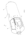
- Figure 1 is an axonometric illustration in part of a suction roll in accordance with the invention for a drying section.
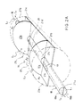
- Figure 2A is an illustration of principle of a suction roll solution in accordance with the invention, and what is shown is in particular a suction box arrangement.
- the illustration is axonometric.
- Figure 2B is a sectional view of the suction roll shown in Fig. 2A.
- Figure 2C is a sectional view taken along the line I-I in Fig. 2B.
- Figure 2D shows the roll as viewed from above.
- Figure 3A shows a second preferred embodiment of a suction roll solution in accordance with the invention.
- the roll is shown as a sectional view.
- Figure 3B is a sectional view taken along the line II-II in Fig. 2A. The wire and the paper web are also shown.
- Figure 3C illustrates the relationship between the cross-sectional flow areas of the grooves and of the perforations in the roll shown in Fig. 3A.
- Figure 4A shows the bearing solution related to the roll shown in Fig. 3.
- the roll is shown as a sectional view.
- Figure 4B shows an embodiment of a paper machine suction roll in accordance with the invention wherein the partition wall is defined by a separate bottom part.
- Figure 4C is a sectional view of the solution shown in Fig. 4B as an illustration of principle.
- Figure 4D is a schematic illustration of an embodiment of the invention wherein negative pressure is introduced into the central vacuum space in the roll through perforations in both of the partition walls.
- Figure 4E shows an embodiment of the invention wherein negative pressure is introduced into the central space in the roll through a perforation formed into one of the partition walls only.
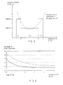
- Figure 5 illustrates a parabolic distribution of negative pressure across the roll width, produced by means of the use of partition walls.
- the vertical system of coordinates represents the negative pressure produced in the interior of the roll, and the horizontal system of coordinates represents the position of width of the roll and the locations of the partition walls.
- Figure 6 illustrates a profile of negative pressure across the width of the roll, produced by means of a method and a roll solution in accordance with the invention.
- the vertical system of coordinates represents the percentage of shrinkage of the paper web from the original web width
- the horizontal system of coordinates represents the position of width of the roll.
- Fig. 1 is an axonometric view of a suction roll 10 in accordance with the invention for a drying section.
- the suction roll 10 comprises a roll mantle 11 and, inside the roll mantle, a suction box 12.
- the suction box 12 defines a suction space 13, and said suction space 13 can be subjected to negative pressure by means of separate means of negative pressure not shown, such as a pump device or equivalent.
- An important field of application of a suction roll in accordance with the invention is in the drying section of a paper machine in locations at which the paper web runs outermost on the wire, whereby the paper web is made to adhere to the wire face by means of negative pressure.
- the longitudinal edges 14 of the suction box 12 are provided with sealing means 15, i.e. with edge seals.
- the sealing means are fitted in sealing seats 16 provided for the sealing means.
- the suction space 13 defined by the suction box 12 in its interior is divided into at least three areas or spaces A1,A2 and A3 across the width of the roll, i.e. in the axial direction of the roll.
- the suction box is provided with partition walls 17.
- one partition wall 17 only is shown.
- the desired negative pressures can be produced at both sides of the partition walls 17.
- the highest negative pressure is produced in the lateral spaces A1 and A3 defined by the partition walls in the suction roll 10.
- a negative pressure of substantially equal magnitude is produced, and said negative pressure is higher than the negative pressure In the middle area of the roll in the space A2.
- the suction roll is provided with bores 11a passing through the roll mantle 11.
- the passage of the air flow is illustrated by means of an arrow.
- Fig. 2A is an illustration of principle of a suction roll construction in accordance with the invention, in particular of the inside construction.
- the suction roll 10 comprises a central axle 18 of rotation, on which the roll mantle 11 of the suction roll 10 is rotated while the bearings at the ends of the roll mantle 11 are coupled with the outer face of the axle 18.
- a second function of the axle 18 is to act as a pipe arrangement by whose means the negative pressure is sucked into the suction space 13 in the suction box 12 inside the roll mantle 11.
- the axle 18 comprises a first duct portion 18a and a second duct portion 18b.
- a corresponding arrangement is provided at the other end of the axle.
- the axle 18 Through the duct portion 18a, negative pressure is sucked into the space A1 between the partition wall 17a and the end of the roll mantle, the axle 18 being provided with an opening 19 at the proximity of the partition wall 17a.
- the other duct 18b in the axle 18 negative pressure is sucked into the space A2 placed at the opposite side of the partition wall 17a, the duct portion 18b in the axle 18 being opened through the opening 20 into the space A2.
- the duct portions 18a and 18b are separated by a partition wall 21a.
- the duct portion 18b Is defined by the wall 21b.
- a higher negative pressure is sucked through the duct 18a than into the space A2 through the duct 18b.
- the negative pressures in the spaces A1 and A3 are substantially equally high.
- the partition wall 17a,17b is connected with a bottom part 21c at both sides of the pipe 18.
- Fig. 2B is a sectional side view of the roll solution shown in Fig. 2A.
- equal negative pressures are produced in the spaces A1 and A3 while the suction flow is directed towards the interior of the roll through holes 23 fitted at the bottom of the circumferential grooves 22 placed in the surface of the roll mantle 11.
- the partition walls 17a and 17b are placed substantially equally far from the roll ends.
- the arrows L1 illustrate the flow through the perforations 23 in the roll mantle 11 into the central space A2 defined by the suction box in its interior and further through the opening 20 into the duct 18b in the interior of the axle 18.
- the partition walls 17a,17b, the bottom parts 21c,21d, and the axle 18 are fitted as stationary.
- the roll mantle 11 revolves on the bearings 11b,11c, while the bearings are supported on the axle 18.
- the arrows L2 illustrate the suction flow through the perforations 23 in the roll mantle 11 into the spaces A1 and A3 and out of said spaces further into the duct 18a in the interior of the axle 18.
- Fig: 2C is a sectional view taken along the line I-I in Fig. 2B.
- the groove 22 shown in the figure comprises a number of holes 23 fitted with the same circumferential spacing. Through the perforations 23, air is made to flow, by means of the negative pressure inside the roll, from outside the roll into its interior and, at the same time, the paper web W running along with the roll is kept in contact with the wire H or equivalent, and in this way the running of the paper web is controlled.
- Fig. 2D shows the roll of Fig. 2B seen from above in the direction of the arrow K1.
- the roll comprises circumferentially fitted grooves, but such an embodiment is also possible in which there is one groove which runs in spiral shape across the entire width of the roll.
- the perforations are fitted in the bottoms of the grooves.
- Fig. 3A shows a second preferred embodiment of the method and device in accordance with the invention.
- the suction roll is shown as a sectional view.
- the suction roll 10 comprises perforations 23 in the bottoms of the grooves 22.
- the roll shown in Fig. 3A does not comprise a suction box inside the roll. Instead, the roll shown in Fig. 3A comprises, in its interior, at least two partition walls 17a,17b at equal distances from the end flanges 27a and 27b of the roll 10.
- the walls 17a and 17b are fixed to the inside face 11' of the mantle 11.
- the axle 18 is a hollow axle, whose duct portion 18a is opened into the spaces A1 and A3 between the partition walls 17a and 17b and the roll ends 27a and 27b.
- a lower negative pressure is introduced into the middle area in the roll in the space between the partition walls A1 and A3.
- a separate pipe duct 24 is opened. Through the pipe 24 or equivalent, a lower negative pressure is sucked into the middle space A2 than into the lateral spaces A1 and A3, in which substantially equally high negative pressures are provided.
- the pipe 24 is supported by means of ribs 25 or equivalent on the duct 18a walls.
- the negative pressure is applied at the same time to the interior of the whole roll mantle 11.
- the roll does not include a separate suction box inside the roll mantle 11.
- Fig. 3B is a sectional view taken along the line II-II in Fig. 3A.
- the figure shows the run of the paper web W and the wire H at the leading cylinders in a single-wire group, for example a single-felt group.
- the cylinder 10 comprises a number of holes 23, preferably bores, ending in the groove 22.
- the holes 23 are fitted as equally spaced in the cylinder mantle on the distance of its circumference.
- negative pressure is produced, e.g., by means of a pump device, and negative pressure is fitted to be present in all operating conditions in said interior space in the drying cylinder 10.
- the negative pressure is applied, at the same time, to the inner face 11' of the entire mantle 11 of the drying cylinder 10.
- a holding force F is applied to the web W, which holding force fixes the web to the face of a wire H of good permeability, for example a fabric, and thereby to the outer face of the drying cylinder 10. In this way, detaching of the web from the cylinder 10 is prevented.
- the upper face of the cylinder 10 remains free from the wire H and the web W. Through said free face S, an air flow is directed without obstacle into the interior space in the drying cylinder 10.
- lowering of the negative pressure in the interior space in the roll is prevented by dimensioning the cross-sectional flow areas of the grooves and the holes so that the negative pressure P can be maintained in the interior of the cylinder 10 in spite of said free flow of air L3 through the area S.
- the perforation through the roll mantle is carried out so that a controlled air flow Q into, and a desired negative pressure in, the interior of the cylinder are achieved.
- a relatively low negative pressure is capable of keeping the web W on the wire face.
- the effect of said negative pressure is spread in the groove 22, and thereby a force area F of the shape of a band, acting upon the web, is obtained.
- Fig. 3C is a schematic illustration of the ratio of the area of the perforations to the area of the grooves provided with perforations.
- the ratio of the total cross-sectional flow area A o of the perforations 23 on the suction roll to the total cross-sectional flow area A1 of the perforated grooves 22 is in the range of 1:10...1:150, and preferably in the range of 1:50...1:110.
- the flow Q per metre of width of the cylinder into the interior space of negative pressure in the cylinder is in the range of 500...1500 m3/m/h, and preferably in the range of 800...1200 m3/m/h.
- the negative pressure in the interior of the suction roll is in the range of 1000...3000 Pa.
- the paper web can be fixed and guided efficiently while the holding force is applied to the paper web in such a way that the web is pressed against the felt along with the roll face also in such draws of the web in which the web is placed outermost and on the surface of the felt.
- the solution in accordance with the invention permits application of the pressure profile across the entire width of the roll and, moreover, in the solution in accordance with the invention, the quality of the paper that is formed is influenced favourably by applying a higher negative pressure to both of the lateral areas of the roll as compared with the middle area of the roll.
- a solution similar to the preceding embodiment is shown, in particular the bearing solution is shown.
- the roll mantle 11 is supported by its end flanges 27a and 27b on the bearing means 26 on the bearing block.
- the axle 18 is a hollow axle, and through said hollow interior space 18a pipe means 24 are passed through the partition wall 17a.
- the roll is divided, by the partition walls 17a and 17b, into three spaces of negative pressure A1,A2,A3. In the spaces A1 and A3 in the lateral parts of the roll, there are substantially equal negative pressures, which are higher than the negative pressure in the middle space A2 in the roll between the partition walls 17a and 17b.
- Fig. 4B is an axonometric illustration in part of a further embodiment of a suction roll in accordance with the invention for a drying section.
- the middle space A2 is formed by means of partition walls 17a and 17b, which partition walls are defined by the inner face of the roll mantle 11 of the suction roll and so also, at the other end, by the cylindrical bottom mantle 28 of circular section.
- the partition wall 17a comprises holes or openings 29. Through the hollow interior space in the axle 30, negative pressure is sucked first into the space A1 and thereupon, through the openings 29, into the space A2.
- the throttle of the holes 29 has the effect that the negative pressure in the space A2 Is lower than in the space A1.
- the perforations in the roll mantle 11 are denoted with the reference numeral 11a.
- Fig. 4C is a sectional view illustrating the principle of the solution shown in Fig. 4B.
- the partition walls 17a and 17b and the bottom mantle 28 By means of the partition walls 17a and 17b and the bottom mantle 28, the space in the interior of the roll is divided into pressure areas P1 and P2. The suction flow is passed out through the axle 30 at one end only.
- the mantle 28 and the partition walls 17a and 17b are fixed permanently to the inner face of the roll mantle 11 and, thus, revolve along with the roll mantle.
- Fig. 4D is a sectional view of a suction roll for a drying section, which comprises walls 17a and 17b and therein openings or holes 31. Negative pressure is produced through the axles 32 and 33 for the spaces A1,A2 and A3.
- Fig. 4E shows an embodiment of the invention wherein the suction roll 10 of the drying section comprises partition walls 17a and 17b and, in the partition wall 17a, at least one opening 34.
- the suction roll 10 of the drying section comprises partition walls 17a and 17b and, in the partition wall 17a, at least one opening 34.
- the axle 35 Through the axle 35, negative pressure is sucked first into the space A2 and thereupon into the space A3 in the middle area of the roll, and through the axle 36 the negative pressure is sucked into the space A3 at the other end of the roll.
- Fig. 5 is a schematic illustration of a parabolic pressure profile, accomplished by means of partition walls, on the face of a paper web. Between the positions 1 and 2 as well as 3 and 4, there is a higher negative pressure than between the positions 2 and 3 in the space A2. In the lateral spaces between the width points 1 and 2; 3 and 4, there is a negative pressure which is about 3000 Pa, and between the width positions 2 and 3 in the space A2, there is a negative pressure which is about 1500 Pa.
- the curve is shown by dashed line that corresponds to the negative pressure at the face of a paper web. The curve is substantially parabolic. Said parabolic shape is affected by the porosity of the wire or equivalent; even though partition walls are used, the negative pressure is equalized efficiently, and there are no points of discontinuity in the curve of the profile of negative pressure measured on the face of the paper web W.
- Fig. 6 illustrates the percentage of shrinkage of the paper web across the width of the paper.
- a conventional solution of suction roll is illustrated by the dashed line, in which solution the same pressure prevails in the interior of the suction roll across the entire width of the suction roll.
- the full line represents the curve that is obtained when a suction roll in accordance with the invention, which is provided with partition walls, is used.
- the shrinkage is indicated as a percentage from the original width of the paper web.
- the horizontal coordinates represent the width position of the roll.
- an embodiment is also possible in which the interior of the roll is divided by more than two partition walls into several spaces A 1 ,A 2 ,A 3 ,A 4 ...A n , in which case in both of the end spaces A 1 and A n in the roll, substantially the same negative pressure prevails, and in the spaces A2 and A n-1 the same negative pressure prevails, etc., and in which case the negative pressure becomes lower when moving towards the middle area of the roll. It is an advantage of such an embodiment that the shape of the profile of negative pressure can be determined more accurately.
- the desired pressure profile is obtained for the suction roll and further for the paper web W by dividing the suction roll in its axial direction into spaces of different pressures by means of partition walls, whose wall planes are substantially perpendicular to the axis X of rotation of the roll 10.
- the invention concerns a suction roll (10) for a paper machine, on which the paper web is pressed towards the outer face of the roll mantle.
- the suction roll (10) is divided, in the axial direction of the roll, into at least three vacuum spaces (A1,A2,A3).
- the lateral vacuum spaces (A1,A3) in the suction space can be subjected to a higher negative pressure than the vacuum space (A2) in the middle area of the roll, whereby the profile of negative pressure is formed such that the negative pressure increases across the width of the roll towards the lateral areas.
- the invention also concerns a method for producing a desired pressure profile for a suction roll.
Landscapes
- Paper (AREA)
- Unwinding Webs (AREA)
- Delivering By Means Of Belts And Rollers (AREA)
- Rolls And Other Rotary Bodies (AREA)
- Advancing Webs (AREA)
Applications Claiming Priority (2)
| Application Number | Priority Date | Filing Date | Title |
|---|---|---|---|
| FI895928 | 1989-12-12 | ||
| FI895928A FI97245C (fi) | 1989-12-12 | 1989-12-12 | Paperikoneen imutela |
Publications (3)
| Publication Number | Publication Date |
|---|---|
| EP0432571A2 true EP0432571A2 (fr) | 1991-06-19 |
| EP0432571A3 EP0432571A3 (en) | 1991-11-06 |
| EP0432571B1 EP0432571B1 (fr) | 1997-09-03 |
Family
ID=8529500
Family Applications (1)
| Application Number | Title | Priority Date | Filing Date |
|---|---|---|---|
| EP90122663A Expired - Lifetime EP0432571B1 (fr) | 1989-12-12 | 1990-11-27 | Rouleau aspirant pour une machine à papier |
Country Status (7)
| Country | Link |
|---|---|
| US (1) | US5135614A (fr) |
| EP (1) | EP0432571B1 (fr) |
| JP (1) | JPH03185192A (fr) |
| AT (1) | ATE157718T1 (fr) |
| CA (1) | CA2031691C (fr) |
| DE (1) | DE69031377T2 (fr) |
| FI (1) | FI97245C (fr) |
Cited By (11)
| Publication number | Priority date | Publication date | Assignee | Title |
|---|---|---|---|---|
| WO1992008004A1 (fr) * | 1990-10-31 | 1992-05-14 | Beloit Corporation | Appareil de sechage |
| DE4222815A1 (de) * | 1991-07-15 | 1993-01-21 | Escher Wyss Gmbh | Vermeidung zirkulationsstroemung in saugwalze |
| AT396263B (de) * | 1991-07-15 | 1993-07-26 | Andritz Patentverwaltung | Saugwalze |
| US5546675A (en) * | 1993-11-22 | 1996-08-20 | Beloit Technologies, Inc. | Single tier drying section apparatus |
| EP0831172A3 (fr) * | 1996-09-11 | 1998-04-01 | Voith Sulzer Papiermaschinen GmbH | Partie toile et procédé de déshydratation d'une bande fibreuse dans une partie toile |
| EP0802277A3 (fr) * | 1996-04-18 | 1998-04-08 | Voith Sulzer Papiermaschinen GmbH | Machine pour la fabrication d'une bande de matériau |
| EP0857821A3 (fr) * | 1997-02-05 | 2000-03-29 | Voith Sulzer Papiertechnik Patent GmbH | Dispositif d'aspiration |
| WO2002046077A1 (fr) * | 2000-12-07 | 2002-06-13 | Brückner Maschinenbau GmbH | Cylindre aspirant |
| EP1234911A3 (fr) * | 2001-02-22 | 2003-12-10 | Voith Paper Patent GmbH | Profil sens travers de la humidité |
| US8801902B1 (en) * | 2013-09-18 | 2014-08-12 | Usg Interiors, Llc | Water reduction by modulating vacuum |
| WO2015033242A2 (fr) | 2013-09-06 | 2015-03-12 | Kimberly-Clark Worldwide, Inc. | Plaque pour un contre-cylindre avec une zone de vide réduit pour une utilisation dans un système de glissement-découpe et procédé d'utilisation correspondant |
Families Citing this family (19)
| Publication number | Priority date | Publication date | Assignee | Title |
|---|---|---|---|---|
| US5281308A (en) * | 1992-04-20 | 1994-01-25 | Beloit Technologies, Inc. | Pick-up roll apparatus |
| WO1997013111A1 (fr) * | 1995-10-04 | 1997-04-10 | Tubular Textile Machinery Corporation | Sechoir aspirant servant a traiter des bandes de tissu, en particulier, des textiles tricotes |
| US5716312A (en) * | 1996-01-16 | 1998-02-10 | Kristel; Ira B. | Vacuum cylinder |
| FI99280C (fi) * | 1996-06-24 | 1998-05-11 | Valmet Corp | Menetelmä ja laite rainan kuivatuksessa |
| DE19756203A1 (de) * | 1996-12-23 | 1998-09-24 | Voith Sulzer Papiermasch Gmbh | Naßpartie und Verfahren zur Herstellung einer Faserstoffbahn |
| DE19654420B4 (de) * | 1996-12-24 | 2007-06-14 | Voith Patent Gmbh | Maschine zur Herstellung einer kontinuierlichen Materialbahn |
| FI111861B (fi) * | 1997-12-10 | 2003-09-30 | Metso Paper Inc | Paperi- tai kartonkikoneen tela |
| DE19963469A1 (de) * | 1999-12-29 | 2001-07-05 | Voith Paper Patent Gmbh | Rotierbare Saugwalze |
| JP4706112B2 (ja) * | 2001-03-06 | 2011-06-22 | 株式会社Ihi | カーテンコータにおける塗工液接着力強化方法及び装置 |
| FI117863B (fi) * | 2002-08-09 | 2007-03-30 | Metso Paper Inc | Menetelmä ja laite rainan päänviennissä paperi- tai kartonkirainan rullauksessa |
| US6884323B2 (en) * | 2003-01-31 | 2005-04-26 | Voith Paper Patent Gmbh | Vented main roll for press assembly in a paper machine |
| FI117101B (fi) * | 2005-02-24 | 2006-06-15 | Olavi Savolainen | Laitteisto nesteen poistamiseksi liikkuvasta kudoksesta tai rainasta |
| DE102005036891A1 (de) | 2005-08-05 | 2007-02-08 | Voith Patent Gmbh | Maschine zur Herstellung von Tissuepapier |
| FI118182B (fi) * | 2005-10-25 | 2007-08-15 | Metso Paper Inc | Rainanmuodostuskoneen alipainehihnakuljetin päänvientinauhan viemistä varten |
| FI20065061A7 (fi) * | 2006-01-30 | 2007-07-31 | Valmet Technologies Inc | Menetelmä ja laite kuiturainakoneen, kuten paperi- tai kartonkikoneen kuivatusosassa |
| FI119029B (fi) * | 2006-01-30 | 2008-06-30 | Metso Paper Inc | Menetelmä ja laite kuiturainakoneen, kuten paperi- tai kartonkikoneen kuivatusosassa |
| US11898602B2 (en) | 2018-04-24 | 2024-02-13 | Applied Materials, Inc. | Multi-zone air turn for transport of a flexible substrate |
| DE102020000334A1 (de) * | 2020-01-21 | 2021-07-22 | Hosokawa Alpine Aktiengesellschaft | Vorrichtung und Verfahren zur monaxialen Längenänderung von Folienbahnen |
| DE102022000351A1 (de) | 2022-01-29 | 2023-08-03 | Hosokawa Alpine Aktiengesellschaft | Verfahren und Vorrichtung zur Foliendickenregelung von gereckter im Folienblasverfahren hergestellter Schlauchfolie |
Family Cites Families (12)
| Publication number | Priority date | Publication date | Assignee | Title |
|---|---|---|---|---|
| BE542034A (fr) * | ||||
| US573752A (en) * | 1896-12-22 | Washinoton | ||
| CH602460A5 (fr) * | 1976-05-20 | 1978-07-31 | Bachofen & Meier Firma | |
| FR2355116A1 (fr) * | 1976-06-18 | 1978-01-13 | Valmet Oy | Perfectionnements aux procedes et moyens pour detacher la bande de papier dans la section de la presse d'une machine a papier |
| US4510698A (en) * | 1982-09-29 | 1985-04-16 | Beloit Corporation | Dryer felt run |
| US4980979A (en) * | 1987-02-13 | 1991-01-01 | Beloit Corporation | Vacuum roll transfer apparatus |
| US4876803A (en) * | 1987-02-13 | 1989-10-31 | Beloit Corporation | Dryer apparatus for drying a web |
| US4905379A (en) * | 1987-02-13 | 1990-03-06 | Beloit Corporation | Intermediate vacuum roll for dryer |
| US4882854A (en) * | 1987-05-26 | 1989-11-28 | Beloit Corporation | Guide roll apparatus for a dryer of a paper machine drying section |
| FI82849C (fi) * | 1989-08-18 | 1991-04-25 | Valmet Paper Machinery Inc | Sugvals. |
| US5015336A (en) * | 1989-10-31 | 1991-05-14 | Beloit Corporation | Felt turning suction roll |
| US4974340A (en) * | 1989-10-31 | 1990-12-04 | Beloit Corporation | Vacuum guide roll apparatus |
-
1989
- 1989-12-12 FI FI895928A patent/FI97245C/fi not_active IP Right Cessation
-
1990
- 1990-11-27 EP EP90122663A patent/EP0432571B1/fr not_active Expired - Lifetime
- 1990-11-27 DE DE69031377T patent/DE69031377T2/de not_active Expired - Fee Related
- 1990-11-27 AT AT90122663T patent/ATE157718T1/de not_active IP Right Cessation
- 1990-11-30 JP JP2330909A patent/JPH03185192A/ja active Pending
- 1990-12-05 US US07/624,872 patent/US5135614A/en not_active Expired - Lifetime
- 1990-12-06 CA CA002031691A patent/CA2031691C/fr not_active Expired - Fee Related
Cited By (17)
| Publication number | Priority date | Publication date | Assignee | Title |
|---|---|---|---|---|
| US5241760A (en) * | 1987-02-13 | 1993-09-07 | Beloit Technologies, Inc. | Dryer apparatus |
| WO1992008004A1 (fr) * | 1990-10-31 | 1992-05-14 | Beloit Corporation | Appareil de sechage |
| DE4222815A1 (de) * | 1991-07-15 | 1993-01-21 | Escher Wyss Gmbh | Vermeidung zirkulationsstroemung in saugwalze |
| AT396263B (de) * | 1991-07-15 | 1993-07-26 | Andritz Patentverwaltung | Saugwalze |
| AT396598B (de) * | 1991-07-15 | 1993-10-25 | Andritz Patentverwaltung | Saugwalze |
| US5347728A (en) * | 1991-07-15 | 1994-09-20 | Sulzer Escher Wyss Gmbh | Suction roll, especially for a paper web drier |
| US5546675A (en) * | 1993-11-22 | 1996-08-20 | Beloit Technologies, Inc. | Single tier drying section apparatus |
| EP0802277A3 (fr) * | 1996-04-18 | 1998-04-08 | Voith Sulzer Papiermaschinen GmbH | Machine pour la fabrication d'une bande de matériau |
| US5829164A (en) * | 1996-04-18 | 1998-11-03 | Voith Sulzer Papiermaschinen Gmbh | Method and machine for drying a material web with guide rollers |
| EP0831172A3 (fr) * | 1996-09-11 | 1998-04-01 | Voith Sulzer Papiermaschinen GmbH | Partie toile et procédé de déshydratation d'une bande fibreuse dans une partie toile |
| US6027612A (en) * | 1996-09-11 | 2000-02-22 | Voith Sulze Papiermaschinen Gmbh | Wire section and method of dewatering a fiber web in a wire section web |
| EP0857821A3 (fr) * | 1997-02-05 | 2000-03-29 | Voith Sulzer Papiertechnik Patent GmbH | Dispositif d'aspiration |
| WO2002046077A1 (fr) * | 2000-12-07 | 2002-06-13 | Brückner Maschinenbau GmbH | Cylindre aspirant |
| EP1234911A3 (fr) * | 2001-02-22 | 2003-12-10 | Voith Paper Patent GmbH | Profil sens travers de la humidité |
| WO2015033242A2 (fr) | 2013-09-06 | 2015-03-12 | Kimberly-Clark Worldwide, Inc. | Plaque pour un contre-cylindre avec une zone de vide réduit pour une utilisation dans un système de glissement-découpe et procédé d'utilisation correspondant |
| EP3041772A4 (fr) * | 2013-09-06 | 2017-12-27 | Kimberly-Clark Worldwide, Inc. | Plaque pour un contre-cylindre avec une zone de vide réduit pour une utilisation dans un système de glissement-découpe et procédé d'utilisation correspondant |
| US8801902B1 (en) * | 2013-09-18 | 2014-08-12 | Usg Interiors, Llc | Water reduction by modulating vacuum |
Also Published As
| Publication number | Publication date |
|---|---|
| FI895928L (fi) | 1991-06-13 |
| EP0432571B1 (fr) | 1997-09-03 |
| DE69031377D1 (de) | 1997-10-09 |
| ATE157718T1 (de) | 1997-09-15 |
| US5135614A (en) | 1992-08-04 |
| CA2031691A1 (fr) | 1991-06-13 |
| FI895928A0 (fi) | 1989-12-12 |
| FI97245B (fi) | 1996-07-31 |
| JPH03185192A (ja) | 1991-08-13 |
| DE69031377T2 (de) | 1998-02-26 |
| FI97245C (fi) | 1996-11-11 |
| CA2031691C (fr) | 1996-04-09 |
| EP0432571A3 (en) | 1991-11-06 |
Similar Documents
| Publication | Publication Date | Title |
|---|---|---|
| EP0432571A2 (fr) | Rouleau aspirant pour une machine à papier et un procédé pour la réalisation d'un profil de pression désiré pour un rouleau aspirant | |
| EP0332599B1 (fr) | Procédé et dispositif dans la section de séchage à toile unique d'une machine à papier et un rouleau pour l'utilisation dans le procédé | |
| US4905380A (en) | Method and apparatus in a paper machine single-wire drying group | |
| US5829164A (en) | Method and machine for drying a material web with guide rollers | |
| US6682632B2 (en) | Roll for a paper or board machine | |
| EP0922138B1 (fr) | Methode pour augmenter la vitesse de fonctionnement d'une machine a papier comportant une section de sechage a deux etages | |
| EP0428471B1 (fr) | Rouleau de guidage aspirant | |
| GB1574341A (en) | Method of and means for applying suction to a web suspension layer felt forming wire or assembly of such in a paper-making machine | |
| EP0413671B1 (fr) | Rouleau aspirant | |
| US5546675A (en) | Single tier drying section apparatus | |
| US5172491A (en) | Method and device for drawing a web through a group of drying cylinders | |
| EP0051055B1 (fr) | Dispositif de ventilation de poches de séchage dans un sécheur à rouleaux | |
| US6192602B1 (en) | Method for contact-free drying of a paper web or equivalent | |
| US5996244A (en) | Roll for a paper machine, in particular for a paper drying device, and dryer group for a paper machine | |
| FI92682B (fi) | Levitystela | |
| US6145218A (en) | Drying section and method for drying a material web in such a drying section | |
| EP0794284B1 (fr) | Rouleau aspirant/Cylindre aspirant | |
| US4882011A (en) | Device for generating negative pressure inside a mantle of a revolving roll | |
| FI120251B (fi) | Kone jatkuvan materiaaliradan valmistamiseksi | |
| CA2275324C (fr) | Cylindre pour machine a papier, notamment pour un dispositif secheur, et groupe secheur pour machine a papier | |
| US5020238A (en) | Vacuum guide roll apparatus | |
| FI121077B (fi) | Kuiturainakoneen muodostusosan imutelajärjestely ja imutelan tiivistelista |
Legal Events
| Date | Code | Title | Description |
|---|---|---|---|
| PUAI | Public reference made under article 153(3) epc to a published international application that has entered the european phase |
Free format text: ORIGINAL CODE: 0009012 |
|
| 17P | Request for examination filed |
Effective date: 19901231 |
|
| AK | Designated contracting states |
Kind code of ref document: A2 Designated state(s): AT DE FR GB IT SE |
|
| PUAL | Search report despatched |
Free format text: ORIGINAL CODE: 0009013 |
|
| AK | Designated contracting states |
Kind code of ref document: A3 Designated state(s): AT DE FR GB IT SE |
|
| 17Q | First examination report despatched |
Effective date: 19940630 |
|
| GRAG | Despatch of communication of intention to grant |
Free format text: ORIGINAL CODE: EPIDOS AGRA |
|
| GRAH | Despatch of communication of intention to grant a patent |
Free format text: ORIGINAL CODE: EPIDOS IGRA |
|
| GRAH | Despatch of communication of intention to grant a patent |
Free format text: ORIGINAL CODE: EPIDOS IGRA |
|
| GRAA | (expected) grant |
Free format text: ORIGINAL CODE: 0009210 |
|
| RAP1 | Party data changed (applicant data changed or rights of an application transferred) |
Owner name: VALMET CORPORATION |
|
| AK | Designated contracting states |
Kind code of ref document: B1 Designated state(s): AT DE FR GB IT SE |
|
| PG25 | Lapsed in a contracting state [announced via postgrant information from national office to epo] |
Ref country code: FR Free format text: LAPSE BECAUSE OF FAILURE TO SUBMIT A TRANSLATION OF THE DESCRIPTION OR TO PAY THE FEE WITHIN THE PRESCRIBED TIME-LIMIT Effective date: 19970903 |
|
| REF | Corresponds to: |
Ref document number: 157718 Country of ref document: AT Date of ref document: 19970915 Kind code of ref document: T |
|
| REF | Corresponds to: |
Ref document number: 69031377 Country of ref document: DE Date of ref document: 19971009 |
|
| ITF | It: translation for a ep patent filed | ||
| EN | Fr: translation not filed | ||
| PLBE | No opposition filed within time limit |
Free format text: ORIGINAL CODE: 0009261 |
|
| STAA | Information on the status of an ep patent application or granted ep patent |
Free format text: STATUS: NO OPPOSITION FILED WITHIN TIME LIMIT |
|
| 26N | No opposition filed | ||
| PGFP | Annual fee paid to national office [announced via postgrant information from national office to epo] |
Ref country code: SE Payment date: 19981116 Year of fee payment: 9 |
|
| PGFP | Annual fee paid to national office [announced via postgrant information from national office to epo] |
Ref country code: GB Payment date: 19981127 Year of fee payment: 9 |
|
| PG25 | Lapsed in a contracting state [announced via postgrant information from national office to epo] |
Ref country code: GB Free format text: LAPSE BECAUSE OF NON-PAYMENT OF DUE FEES Effective date: 19991127 |
|
| PG25 | Lapsed in a contracting state [announced via postgrant information from national office to epo] |
Ref country code: SE Free format text: LAPSE BECAUSE OF NON-PAYMENT OF DUE FEES Effective date: 19991128 |
|
| EUG | Se: european patent has lapsed |
Ref document number: 90122663.9 |
|
| GBPC | Gb: european patent ceased through non-payment of renewal fee |
Effective date: 19991127 |
|
| PGFP | Annual fee paid to national office [announced via postgrant information from national office to epo] |
Ref country code: DE Payment date: 20031103 Year of fee payment: 14 |
|
| PGFP | Annual fee paid to national office [announced via postgrant information from national office to epo] |
Ref country code: AT Payment date: 20031105 Year of fee payment: 14 |
|
| PG25 | Lapsed in a contracting state [announced via postgrant information from national office to epo] |
Ref country code: AT Free format text: LAPSE BECAUSE OF NON-PAYMENT OF DUE FEES Effective date: 20041127 |
|
| PG25 | Lapsed in a contracting state [announced via postgrant information from national office to epo] |
Ref country code: DE Free format text: LAPSE BECAUSE OF NON-PAYMENT OF DUE FEES Effective date: 20050601 |
|
| PG25 | Lapsed in a contracting state [announced via postgrant information from national office to epo] |
Ref country code: IT Free format text: LAPSE BECAUSE OF NON-PAYMENT OF DUE FEES;WARNING: LAPSES OF ITALIAN PATENTS WITH EFFECTIVE DATE BEFORE 2007 MAY HAVE OCCURRED AT ANY TIME BEFORE 2007. THE CORRECT EFFECTIVE DATE MAY BE DIFFERENT FROM THE ONE RECORDED. Effective date: 20051127 |