EP0432584A2 - Dispositif de pulv˩risation de fluide - Google Patents
Dispositif de pulv˩risation de fluide Download PDFInfo
- Publication number
- EP0432584A2 EP0432584A2 EP90122821A EP90122821A EP0432584A2 EP 0432584 A2 EP0432584 A2 EP 0432584A2 EP 90122821 A EP90122821 A EP 90122821A EP 90122821 A EP90122821 A EP 90122821A EP 0432584 A2 EP0432584 A2 EP 0432584A2
- Authority
- EP
- European Patent Office
- Prior art keywords
- spray device
- particular according
- liquid spray
- liquid
- threaded jaws
- Prior art date
- Legal status (The legal status is an assumption and is not a legal conclusion. Google has not performed a legal analysis and makes no representation as to the accuracy of the status listed.)
- Withdrawn
Links
Images




Classifications
-
- B—PERFORMING OPERATIONS; TRANSPORTING
- B05—SPRAYING OR ATOMISING IN GENERAL; APPLYING FLUENT MATERIALS TO SURFACES, IN GENERAL
- B05B—SPRAYING APPARATUS; ATOMISING APPARATUS; NOZZLES
- B05B9/00—Spraying apparatus for discharge of liquids or other fluent material, without essentially mixing with gas or vapour
- B05B9/03—Spraying apparatus for discharge of liquids or other fluent material, without essentially mixing with gas or vapour characterised by means for supplying liquid or other fluent material
- B05B9/04—Spraying apparatus for discharge of liquids or other fluent material, without essentially mixing with gas or vapour characterised by means for supplying liquid or other fluent material with pressurised or compressible container; with pump
- B05B9/08—Apparatus to be carried on or by a person, e.g. of knapsack type
- B05B9/085—Apparatus to be carried on or by a person, e.g. of knapsack type with a liquid pump
- B05B9/0877—Apparatus to be carried on or by a person, e.g. of knapsack type with a liquid pump the pump being of pressure-accumulation type or being connected to a pressure accumulation chamber
- B05B9/0883—Apparatus to be carried on or by a person, e.g. of knapsack type with a liquid pump the pump being of pressure-accumulation type or being connected to a pressure accumulation chamber having a discharge device fixed to the container
Definitions
- the invention relates to a liquid spray device with a metering chamber connected to a mouthpiece opening according to the preamble of patent claim 1.
- a liquid spray device of this type is known from DE-PS 22 22 466.
- the piston is sucked in via a slotted slot on the piston shaft.
- a so-called sliding block engages in the slot.
- the latter consists of a ball.
- the ball itself runs in a vertical groove in the housing.
- the rising section of the slotted slot is set so that the entire stroke of the piston is traversed with less than one full rotation of the dispenser head. Both ends of the rising section of the slot slot merge into a vertical groove. Entered into this groove, the sliding block suddenly releases the energy accumulator when an opening valve of the mouthpiece opening is actuated.
- the energy accumulator which loads the piston permanently in the direction of emptying, consists of a helical compression spring.
- US Pat. No. 4,167,941 even proposes to drive several small pistons by rotating the dispenser head.
- the pistons which are arranged radially and in opposite directions transversely to the longitudinal center axis of the liquid spraying device, engage with their piston shaft via a control pin in a zigzag-shaped link slot which follows a circular path, taking into account the rotatability of the dispenser head. Sucking in the liquid in small steps via a riser tube requires a lot of "turning work”.
- the object of the present invention is to provide a generic liquid spray device while avoiding the disadvantages shown in a technically simple, use-reliable manner such that despite the application of high storage force creating a stable spray jet, there is no damage to the dispenser mechanism in operationally different situations.
- the energy accumulator is charged by means of a hand crank supply.
- a hand crank for example comparable to that of a mocha mill, also enables ergonomically favorable handling.
- the dispenser housing is gripped with one hand and the crank handle with the other.
- the lever ratios can even be optimized if the procedure is continued such that the hand crank is arranged so that it can be folded out radially on a rotating ring on the head side of the liquid spray device. By unfolding a considerable arm length can be added.
- Such a hand crank naturally still has the usual, rotatably mounted crank knob in order to also be able to offer a convenient method of operation.
- the rotating ring engages with a thread on the shaft of the piston, the thread pitch of which lies in the self-locking area, and the associated engaging thread jaws (nut) can be opened for decoupling when the energy storage pressure is absorbed by the abutment of the liquid subset.
- the threaded jaws remain closed until the piston that is cranked back hits the abutment formed by the amount of liquid or even the bottom of the metering chamber. In the case of a normally filled dosing chamber, this practically happens when the rotating ring is partially turned back, during which movement the fold-out crank arm is folded back in depending on the control.
- the thread pitch can be 3 mm.
- the self-locking prevents a spring-induced displacement of the piston in the direction of emptying as long as the thread engagement still exists.
- a common locking member is assigned to the threaded jaws, which blocks movement of the threaded jaws in the decoupling direction when there is no effective abutment due to the liquid subset.
- Such a locking member can consist of a plate-like body like the threaded jaws.
- the procedure here is such that the threaded jaws are pivotally mounted in a scissor-like manner with respect to one another in the rotating ring and the locking member is arranged below the threaded jaws, with the mutually facing surfaces of the locking member and the threaded jaws having interlocking toothed ribs which are transverse to the Uncoupling direction of the threaded jaws run and stand apart from each other with the energy storage pressure absorbed by the abutment.
- a normal tooth structure with a triangular cross-section may serve to create the relevant interlocking engagement, with one side of the triangle being rooted in the respective surface and the triangle tips being directed towards one another.
- the leading jaws are actuated by a pin / cam slot control, which is arranged on the side opposite the bearing pin. It is further proposed that the pin of the cam slot control is also the carrier of the hand crank. This gives this element another function. Fewer components are required. It also proves to be favorable that the hand crank has a curvature corresponding approximately to the circumferential curvature of the rotating ring and can be folded into a vertically open slot which extends around a partial circumference of the rotating ring.
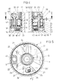
- the dispenser Sp containing the liquid spraying device according to the invention is designed as an elongated, essentially cylindrical free-standing device, comprising an upper head part 1, a middle connecting part 2 and a cup-like receiving part 3 which can be assigned to this in terms of screw technology.
- the latter holds a cartridge 5 containing liquid 4.
- the centerpiece of the liquid spray device is a centrally located metering chamber 8.
- a piston 9 is displaceable axially within it.
- the metering chamber is formed by a cylinder 10 of an insert part.
- the piston 9, consisting of a piston plate with a stretched elastic sealing ring liquid 4 is conveyed from the storage chamber 11 enclosed by the cartridge 5 in a divided amount into the metering chamber 8, i. H. sucked.
- the approximately maximum subset correspondingly shown in FIG. 9 bears the reference symbol 4 '.
- a riser pipe 13 extends centrally from the bottom 12 of the metering chamber 8. The lower end of the latter extends to just before the bottom of the cartridge 5 or storage chamber 11. The upper end of the riser pipe 13 is seated in a socket 14 which is molded onto the bottom 12.
- the bottom section of the nozzle 14 forms a valve chamber to form a so-called inlet valve V1. Specifically, it is a ball valve.
- the piston 9 is under the load of the force of a force accumulator K.
- This is realized as a compression spring 15.
- the compression spring 15 loads the back of the piston 9 with its lower end turn, while the upper end turn is supported on an intermediate wall 16 of the housing, more precisely the connecting part 2.
- This intermediate wall 16 extends horizontally, that is transverse to the longitudinal central axis xx of the basically rotationally symmetrical dispenser Sp.
- the compression spring 15 is received in an axially aligned annular chamber, the outer end of which forms the wall of the cylinder 10 and the inner boundary of which is the outer wall of the shaft 17 of the piston 9.
- the metering chamber 8 is assigned to the connecting part 2 by means of the screw connection, using the same thread that also uses the receiving part 3.
- the threaded collar on the cylinder side of the corresponding insert is designated by 18. It is an angular shaped cross-section on the outer wall of the cylinder 10 with an upwardly directed ring web.
- the underside of the horizontal section of the angular formation forms the contact surface for the ring seal 7.
- the same ring seal is also used by a neck piece 19 of the cartridge 5, which neck piece 19 can possibly also step against the said ring seal 7 with its end face near the cylinder.
- the loading of the energy accumulator K while simultaneously sucking in the partial quantity 4 ′ is effected via a disengageable thread engagement and the rotary movement of a rotary ring 20.
- the latter forms the head part 1 of the dispenser Sp and projects beyond the connection part 2 in an accessible manner.
- the rotary ring 20 is the carrier of two threaded jaws 21, which engage with their internal thread 22 in the external thread 23 of the piston shaft 17. In the engaged state, there is a closed internal thread like a nut.
- the pitch of the thread denoted as a whole by G lies in the self-locking range (approx. 7 °).
- the designated journal 24 extends as close as possible in the area of the inner wall of the connecting part 2.
- the geometrical (corresponding to the physical) axis of the journal 24 runs parallel to the longitudinal center axis xx of the dispenser Sp.
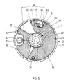
- the thread jaws 21 are each halved in thickness, so that they overlap, as can be seen, for example, from FIG. 5, without the general load-bearing thickness of the threaded jaws 21 being exceeded.
- the same overlapping overlapping with halving the plate thickness of the two threaded jaws 21 is also carried out at their free end.
- the overlap area given in diametrical opposite to the journal 24 still includes an angle of approximately 50 ° when the threaded jaws 21 are open.
- a further pin 25 penetrates the bisector. The latter is used to form a cam slot control.
- the latter proceed from the pin 25 in the manner of a key beard. They face each other in the opposite direction. If the pin 25 is based on that shown in Figure 5 th open position of the threaded jaws 21 rotated in the direction of the arrow y, the control fingers 27 finally hit against the control slot flanks 26 'lying approximately 90 ° to one another, which leads to a closing contraction of the threaded jaws 21.
- the pin 25 also has another function, namely it is also the carrier of a hand crank 28. With the help of this hand crank 28, the rotating ring 20 can be actuated in the sense of conditioning the dispenser Sp.
- the upper pin end 25 ′ facing the rotary ring 20 is seated in a bearing recess 29 of the rotary ring.
- the pin 25 is also seated as far as possible in the area of the periphery of the rotary ring 20, the effective lever arm being lengthened as cheaply as possible by means of the fact that the hand crank 28 can also be folded out (by approximately 180 °). This and the relatively small pitch angle of the thread G enable the energy store K to be conveniently charged.
- the cam slot control is matched to the 180 ° mentioned.
- the hand crank 28 has an inversely curved course, such that it does not project outward beyond the cross-sectional outline of the dispenser Sp in the space-saving, collapsed position.
- the curvature corresponding to the circumferential curvature of the rotating ring 20 results from FIG. 2, as does the slot 32 which receives the crank body and is open radially outwards and extends around a partial circumference of the rotating ring 20 which is approximately 270 °.
- crank handle 28 In the unfolded position, the back portion 28 ′ of the crank handle 28 closer to the pin 25 hits a stop shoulder 33 of the rotary ring 20, which stop shoulder forms the end of the slot 32 there.
- the free end of the crank handle 28 carries a customary, rotatably mounted crank knob 34 which points upwards and in the closed position hits the other stop shoulder 35 of the slot 32 which is partially open upwards.
- the hollow piston shaft 17 is controlled by a so-called outlet valve V2, which sits in the head part 1 of the dispenser Sp.
- the central channel of the shaft 17 is denoted by 36 and is connected in terms of flow technology to a mouthpiece opening 37 designed as a spray nozzle.
- the component of the discharge barrier forming blocking member 31 extends below the screw jaws 21, which are effectively arranged at the same height from one another, in such a way that the surfaces of the threaded jaws 21 and the corresponding surface of the blocking member 31 face each other in a touching manner. Both surfaces are provided with toothed ribs.
- the toothed ribs of the threaded jaws are called a; the toothed ribs of the locking member 31 have the reference symbol b.
- the toothed ribs a and b extend transversely to the decoupling pivot direction of the threaded jaws 21, d. H. they take a course of a journal 24 and journal 25 directly connecting line and parallel to it.
- toothed ribs which are triangular in cross section, one side of which is rooted in the respective surface of the threaded jaws 21 or the locking member 31, while the tooth tips of the two parts are turned towards one another. In the meshing position there is a complete positive connection. This means that the toothed ribs of one surface are offset by half a toothed rib width from the other. Said positive engagement is only in the position in which the internal thread 22 of the threaded jaws 21 has entered the external thread 23 of the shaft 17 of the piston 9.
- a thrust bearing 38 directly locking the locking member 31 is provided, consisting of a ball bearing ring 39 and upper and lower support ring 40 38 is located in an upwardly open annular groove 41, which is also taken into account in terms of shape on the connection part 2, the bottom of which is formed by a corresponding section of the upper side of the intermediate wall 16.
- the peripheral termination of the annular groove 41 is provided by an upwardly pointing ring web 42 and on the inside a likewise upwardly directed collar 43.
- the collar 43 protrudes on the outside, supported in a central opening 44 in the locking member 31, and is sufficiently spaced apart from the toothing of the toothed ribs a extending on the upper side , b.
- the intermediate wall 16 forms a type of partition between an upper receiving space containing the threaded jaws 21 and the locking member 31 and the plug-in or fastening assignment space for the cartridge 5 underneath. It is seen, as seen, a rotationally symmetrical T-profile, the web of which annular partition 16 is.
- a circumferential groove 45 is left in the inner wall of the upper receiving space, into which the edge of the locking member 31 is clipped.
- Locking element 31 and rotating ring 20 are fastened via a fastening which is aligned parallel to the longitudinal central axis xx screw 46 connected together.
- a threaded standing sleeve 47 extends from the top of the locking member 31 in a toothed rib-free section. This standing sleeve 47, which also functions as a spacer sleeve, receives the shaft of the fastening screw 46, which is seated on the shoulder 48 from the top of the rotary ring 20.
- the shaft 17 of the piston 9 which penetrates the rotary ring 20 freely and centrally is, in its upper, free region, carrier T of an actuating handle 49 of the outlet valve V2 which is stationary relative to the rotary ring 20 and has the mouthpiece opening 37.
- the actuating handle 49 is designed as a push button. Its shaft 50, which is sprung in the direction of the basic position, has a channel 51, the transverse stitch channel 52 of which can be displaced from a closed position, so that the flow path to the channel 36 is free. Further details are unnecessary, since such designs are known.
- a sliding bush 53 is screwed onto the carrier T, that is to say onto the free end of the shaft 17, with the addition of a telescopic bush 53 ', the outer surface of which forms the guide pin for the rotary ring 20.
- An attachable protective cap 54 covers the head part 1 of the dispenser.
- the hand crank 28 is folded out and pivoted in the direction of the arrow y.
- the threaded jaws 21 are in threaded engagement with the shaft 17.
- the prestressing force of the energy accumulator K maintains the positive connection between the threaded jaws 21 and the locking member 31.
- the piston 9 can be raised relatively smoothly in the direction of the arrow z with entrainment of the carrier T until the protrusion position shown in FIG. 9 results, in which the dosing chamber 8 is filled. It (9) is frictionally secured against turning.
- the hand crank is now brought back into its hiding position, which is done by initially unscrewing the shaft 17, since the threaded jaws 21 can only be brought into engagement externally when the energy storage discharge lock is released. However, this is only canceled when the piston 9 reaches the abutment W formed by the mirror of the divided subset 4 '. If the piston 9 now touches down, the relative displacement to the device causes the positive locking between the locking member 31 and the threaded jaws 21 to be canceled. These can move upwards as a result of a left axial clearance F. The corresponding alternative position is shown in FIG. 4. If the positive locking between the toothed ribs a and b is removed, the clamping jaws can also be lifted off the thread G of the shaft 17 according to the cam slot control 26, 27.
- the liquid portion 4 ' is under full pressure.
- a jet which is practically stable until it is emptied can now be discharged through the mouthpiece opening 37.
- the orientation of the dispenser is also irrelevant, which means that it can also be operated upside down while maintaining the same spray pattern.
- the outer surface of the connecting part 2 has a roughening; specifically, these are rough grooves 55 interrupted approximately in the middle section.
- the storage chamber 11 is connected to the atmosphere via an air compensation opening, not shown.
Landscapes
- Containers And Packaging Bodies Having A Special Means To Remove Contents (AREA)
Applications Claiming Priority (2)
| Application Number | Priority Date | Filing Date | Title |
|---|---|---|---|
| DE3941088 | 1989-12-13 | ||
| DE19893941088 DE3941088A1 (de) | 1989-12-13 | 1989-12-13 | Fluessigkeitsspruehvorrichtung |
Publications (2)
| Publication Number | Publication Date |
|---|---|
| EP0432584A2 true EP0432584A2 (fr) | 1991-06-19 |
| EP0432584A3 EP0432584A3 (en) | 1991-12-18 |
Family
ID=6395343
Family Applications (1)
| Application Number | Title | Priority Date | Filing Date |
|---|---|---|---|
| EP19900122821 Withdrawn EP0432584A3 (en) | 1989-12-13 | 1990-11-29 | Fluid spray device |
Country Status (2)
| Country | Link |
|---|---|
| EP (1) | EP0432584A3 (fr) |
| DE (1) | DE3941088A1 (fr) |
Cited By (5)
| Publication number | Priority date | Publication date | Assignee | Title |
|---|---|---|---|---|
| FR2695575A1 (fr) * | 1991-11-22 | 1994-03-18 | Wassilieff Victor | Dispositif comportant deux chambres formées en tandem et un élément commun axialement déplaçable assurant la diffusion sous pression d'un fluide contenu dans un récipient. |
| FR2703930A1 (fr) * | 1993-04-14 | 1994-10-21 | Wassilieff Victor | Dispositif assurant la diffusion sous pression d'un produit liquide ou pâteux par armement préalable obtenu par rotation. |
| WO1996012566A1 (fr) * | 1994-10-20 | 1996-05-02 | Victor Wassilieff | Dispositif assurant la diffusion sous pression d'un produit fluide |
| EP0504402B1 (fr) * | 1990-10-05 | 1997-03-26 | Yoshino Kogyosho Co., Ltd. | Atomiseur de liquide |
| EP2841352A4 (fr) * | 2012-04-11 | 2015-12-23 | Alternative Packaging Solutions Llc | Distributeur à pulvérisation et à durée activée par un tour |
Family Cites Families (2)
| Publication number | Priority date | Publication date | Assignee | Title |
|---|---|---|---|---|
| GB1379182A (en) * | 1971-06-10 | 1975-01-02 | Yoshino Kogyosho Co Ltd | Spraying device |
| GB1408497A (en) * | 1972-04-15 | 1975-10-01 | Yoshino Kogyosho Co Ltd | Liquid spraying devic3 |
-
1989
- 1989-12-13 DE DE19893941088 patent/DE3941088A1/de not_active Withdrawn
-
1990
- 1990-11-29 EP EP19900122821 patent/EP0432584A3/de not_active Withdrawn
Cited By (6)
| Publication number | Priority date | Publication date | Assignee | Title |
|---|---|---|---|---|
| EP0504402B1 (fr) * | 1990-10-05 | 1997-03-26 | Yoshino Kogyosho Co., Ltd. | Atomiseur de liquide |
| FR2695575A1 (fr) * | 1991-11-22 | 1994-03-18 | Wassilieff Victor | Dispositif comportant deux chambres formées en tandem et un élément commun axialement déplaçable assurant la diffusion sous pression d'un fluide contenu dans un récipient. |
| FR2703930A1 (fr) * | 1993-04-14 | 1994-10-21 | Wassilieff Victor | Dispositif assurant la diffusion sous pression d'un produit liquide ou pâteux par armement préalable obtenu par rotation. |
| WO1996012566A1 (fr) * | 1994-10-20 | 1996-05-02 | Victor Wassilieff | Dispositif assurant la diffusion sous pression d'un produit fluide |
| EP3222363A1 (fr) * | 2008-07-14 | 2017-09-27 | Alternative Packaging Solutions, LLC | Distributeur à pulvérisation à durée activée par un tour |
| EP2841352A4 (fr) * | 2012-04-11 | 2015-12-23 | Alternative Packaging Solutions Llc | Distributeur à pulvérisation et à durée activée par un tour |
Also Published As
| Publication number | Publication date |
|---|---|
| DE3941088A1 (de) | 1991-06-20 |
| EP0432584A3 (en) | 1991-12-18 |
Similar Documents
| Publication | Publication Date | Title |
|---|---|---|
| EP3055073B1 (fr) | Dispositif de délivrance doté d'une sécurité pour les enfants | |
| DE2447426A1 (de) | Spruehvorrichtung | |
| DE3114873C2 (fr) | ||
| EP0311863B1 (fr) | Dispositif de distribution de fluide | |
| EP1009541A1 (fr) | Pompe de pulverisation pouvant etre actionnee par un levier a main | |
| DE3104450A1 (de) | "fluessigkeitsinjektor der druecker-bauart" | |
| EP1268301A1 (fr) | Bouchon a vis avec pinceau | |
| DE3339180A1 (de) | Wirkstoffspender | |
| WO1997046324A1 (fr) | Appareil pour distribuer des liquides | |
| DE1290499B (de) | Reisezerstaeuber fuer Parfum, Toilettenwasser od. dgl. | |
| DE2531919A1 (de) | Betaetigungsvorrichtung fuer den stoessel eines aerosolventiles | |
| EP0284907B1 (fr) | Distributeur de produits visqueux | |
| DE3124586C2 (fr) | ||
| EP0053329A1 (fr) | Récipient pour distribuer en portions un produit de consistance pâteuse | |
| DE102018002101A1 (de) | Abgabespeicher und Spender | |
| DE4004653A1 (de) | Fluessigkeitsspruehvorrichtung | |
| DE102013202933B3 (de) | Kindergesicherte Austragvorrichtung | |
| EP0432584A2 (fr) | Dispositif de pulv˩risation de fluide | |
| DE10015968A1 (de) | Spender für Medien | |
| DE3834091A1 (de) | Spraypumpe | |
| EP1674162B1 (fr) | Pompe de dosage avec un élément d'actionnement rotatif | |
| EP0431304A2 (fr) | Dispositif pour l'expulsion par étapes d'un produit | |
| WO2006027313A1 (fr) | Inhalateur | |
| DE1296003B (de) | Verschliesseinrichtung fuer den Behaelterinhalt bei einer Spruehpumpe | |
| DE20019540U1 (de) | Dosierpumpe aus Kunststoff für pastenartige Medien |
Legal Events
| Date | Code | Title | Description |
|---|---|---|---|
| PUAI | Public reference made under article 153(3) epc to a published international application that has entered the european phase |
Free format text: ORIGINAL CODE: 0009012 |
|
| AK | Designated contracting states |
Kind code of ref document: A2 Designated state(s): AT BE CH DE DK ES FR GB GR IT LI LU NL SE |
|
| PUAL | Search report despatched |
Free format text: ORIGINAL CODE: 0009013 |
|
| AK | Designated contracting states |
Kind code of ref document: A3 Designated state(s): AT BE CH DE DK ES FR GB GR IT LI LU NL SE |
|
| STAA | Information on the status of an ep patent application or granted ep patent |
Free format text: STATUS: THE APPLICATION IS DEEMED TO BE WITHDRAWN |
|
| 18D | Application deemed to be withdrawn |
Effective date: 19920619 |