EP0432738B1 - Unité de combustible pour un réacteur à eau bouillante - Google Patents
Unité de combustible pour un réacteur à eau bouillante Download PDFInfo
- Publication number
- EP0432738B1 EP0432738B1 EP90123849A EP90123849A EP0432738B1 EP 0432738 B1 EP0432738 B1 EP 0432738B1 EP 90123849 A EP90123849 A EP 90123849A EP 90123849 A EP90123849 A EP 90123849A EP 0432738 B1 EP0432738 B1 EP 0432738B1
- Authority
- EP
- European Patent Office
- Prior art keywords
- tie plate
- fuel assembly
- strainer
- fuel
- debris catcher
- Prior art date
- Legal status (The legal status is an assumption and is not a legal conclusion. Google has not performed a legal analysis and makes no representation as to the accuracy of the status listed.)
- Revoked
Links
- 239000000446 fuel Substances 0.000 title claims description 83
- XLYOFNOQVPJJNP-UHFFFAOYSA-N water Substances O XLYOFNOQVPJJNP-UHFFFAOYSA-N 0.000 title claims description 24
- 238000009835 boiling Methods 0.000 title claims description 6
- 230000000712 assembly Effects 0.000 claims description 16
- 238000000429 assembly Methods 0.000 claims description 16
- 239000002184 metal Substances 0.000 claims description 8
- 125000006850 spacer group Chemical group 0.000 description 5
- OKTJSMMVPCPJKN-UHFFFAOYSA-N Carbon Chemical compound [C] OKTJSMMVPCPJKN-UHFFFAOYSA-N 0.000 description 2
- CURLTUGMZLYLDI-UHFFFAOYSA-N Carbon dioxide Chemical compound O=C=O CURLTUGMZLYLDI-UHFFFAOYSA-N 0.000 description 2
- 239000002826 coolant Substances 0.000 description 2
- 239000000498 cooling water Substances 0.000 description 2
- 229910002804 graphite Inorganic materials 0.000 description 2
- 239000010439 graphite Substances 0.000 description 2
- 239000002245 particle Substances 0.000 description 2
- 229910000831 Steel Inorganic materials 0.000 description 1
- 238000005299 abrasion Methods 0.000 description 1
- 229910002092 carbon dioxide Inorganic materials 0.000 description 1
- 239000001569 carbon dioxide Substances 0.000 description 1
- 238000005253 cladding Methods 0.000 description 1
- 238000011161 development Methods 0.000 description 1
- 230000018109 developmental process Effects 0.000 description 1
- 230000000694 effects Effects 0.000 description 1
- 230000004992 fission Effects 0.000 description 1
- 238000007373 indentation Methods 0.000 description 1
- 239000000463 material Substances 0.000 description 1
- 239000000047 product Substances 0.000 description 1
- 230000002285 radioactive effect Effects 0.000 description 1
- 239000007787 solid Substances 0.000 description 1
- 239000010959 steel Substances 0.000 description 1
- 239000013589 supplement Substances 0.000 description 1
- 238000003466 welding Methods 0.000 description 1
Images




Classifications
-
- G—PHYSICS
- G21—NUCLEAR PHYSICS; NUCLEAR ENGINEERING
- G21C—NUCLEAR REACTORS
- G21C3/00—Reactor fuel elements and their assemblies; Selection of substances for use as reactor fuel elements
- G21C3/30—Assemblies of a number of fuel elements in the form of a rigid unit
- G21C3/32—Bundles of parallel pin-, rod-, or tube-shaped fuel elements
-
- G—PHYSICS
- G21—NUCLEAR PHYSICS; NUCLEAR ENGINEERING
- G21C—NUCLEAR REACTORS
- G21C3/00—Reactor fuel elements and their assemblies; Selection of substances for use as reactor fuel elements
- G21C3/30—Assemblies of a number of fuel elements in the form of a rigid unit
- G21C3/32—Bundles of parallel pin-, rod-, or tube-shaped fuel elements
- G21C3/3206—Means associated with the fuel bundle for filtering the coolant, e.g. nozzles, grids
-
- G—PHYSICS
- G21—NUCLEAR PHYSICS; NUCLEAR ENGINEERING
- G21C—NUCLEAR REACTORS
- G21C19/00—Arrangements for treating, for handling, or for facilitating the handling of, fuel or other materials which are used within the reactor, e.g. within its pressure vessel
- G21C19/28—Arrangements for introducing fluent material into the reactor core; Arrangements for removing fluent material from the reactor core
- G21C19/30—Arrangements for introducing fluent material into the reactor core; Arrangements for removing fluent material from the reactor core with continuous purification of circulating fluent material, e.g. by extraction of fission products deterioration or corrosion products, impurities, e.g. by cold traps
- G21C19/307—Arrangements for introducing fluent material into the reactor core; Arrangements for removing fluent material from the reactor core with continuous purification of circulating fluent material, e.g. by extraction of fission products deterioration or corrosion products, impurities, e.g. by cold traps specially adapted for liquids
-
- Y—GENERAL TAGGING OF NEW TECHNOLOGICAL DEVELOPMENTS; GENERAL TAGGING OF CROSS-SECTIONAL TECHNOLOGIES SPANNING OVER SEVERAL SECTIONS OF THE IPC; TECHNICAL SUBJECTS COVERED BY FORMER USPC CROSS-REFERENCE ART COLLECTIONS [XRACs] AND DIGESTS
- Y02—TECHNOLOGIES OR APPLICATIONS FOR MITIGATION OR ADAPTATION AGAINST CLIMATE CHANGE
- Y02E—REDUCTION OF GREENHOUSE GAS [GHG] EMISSIONS, RELATED TO ENERGY GENERATION, TRANSMISSION OR DISTRIBUTION
- Y02E30/00—Energy generation of nuclear origin
- Y02E30/30—Nuclear fission reactors
Definitions
- the invention relates to a fuel assembly for a boiling water nuclear reactor according to the precharacterising part of claim 1.
- a fuel assembly is already known from the SE-B-450 177.
- the debris may enter, which debris then move with the water circulating through the reactor core.
- the debris may for example, consist of metal chips (borings) formed in connection with repair of, for example, a steam separator, pieces of metal wire, or other foreign particles which have entered the system from outside.
- the debris may give rise to abrasion damage, which has serious consequences if the damage arises on parts which are particularly easily damaged, such as fuel rods.
- the DE-A-1 028 705 describes a nuclear reactor with a reactor core formed of a graphite block with holes into which fuel assemblies are inserted.
- the moderator is formed by the graphite.
- the coolant consists of a gas, preferably carbon dioxide, which flows upwards through the fuel assemblies.
- the filter element has a long cylindrical shape extending in the axial direction of the fuel assembly.
- the invention aims at developing a fuel assembly for a boiling water nuclear reactor of the above-mentioned kind with a debris catcher which can easily be supplemented to already existing fuel assemblies and which is not susceptible to uneven water supply in case of partial clogging of the debris catcher.
- the invention suggests a fuel assembly for a boiling water nuclear reactor according to the introductory part of claim 1, which is characterized by the features of the characterizing part of claim 1.
- One advantage of locating the debris catcher according to the invention below the bottom tie plate is that the flow, because of the distance between the debris catcher and the bottom tie plate, has time to even itself out if some part of the debris catcher should be clogged.
- Another advantage of the invention is that it is possible in a simple way to supplement already existing fuel assemblies with debris catchers.
- the debris catcher consists of a strainer, parallel to the bottom tie plate, preferably in the form of a strainer plate. If the strainer is arranged below the bottom tie plate, it has, in addition to the advantages mentioned above, the advantage of being capable of being inspected as well as being capable of being removed and cleaned without any problems.
- a strainer parallel to the bottom tie plate is preferably arranged with an edge zone in the form of a gap towards adjacent parts of the fuel assembly, preferably with lower relative flow resistance than in the strainer itself and provided with projections extending into the edge zone.
- the strainer is arranged above the bottom tie plate, it is formed with holes for end plugs at the bottom of the fuel rods, the holes being preferably larger than the cross section of the end plugs so that internal zones preferably with lower relative flow resistance than in the rest of the strainer exist around the end plugs, and further provided with projections which extend into the internal zones.
- the debris catcher consists of a container which is arranged below the bottom tie plate and which has limiting walls, parallel to the bottom tie plate and provided with holes, and which container contains a sparse stack of folded sheets.
- the debris catcher is formed as a unit common to four fuel assemblies.
- four fuel assemblies of the same kind are arranged adjacent to each other around a common channel for water, and the bottom part is formed as a vertical tube with an upper conical portion, which is connected to the outwardly-facing bottom portions of the casing parts of the fuel assemblies.
- the debris catcher may consist of a funnel-shaped strainer, arranged in the conical portion of the bottom part, with the narrower part of the funnel directed downwards.
- the strainer may cover the entire cross section of the tube.
- the strainer may be provided with an opening at its narrower funnel end which takes up a considerable part of the cross section of the tube.
- the debris catcher comprises a number on concentric sheet metal cones, arranged in the conical portion of the bottom part and provided at the upper end with an outwardly-directed, bent-down edge for catching debris.
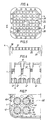
- numeral 1 designates a fuel channel with substantially square cross section.
- the fuel channel surrounds, with no significant play, an upper square portion of a bottom part 2, which has a circular, downwardly-facing inlet opening 3 for cooling water and moderator water.
- the bottom part 2 also supports a supporting plate 4.
- the fuel channel 1 has a relatively thick wall portion which is fixed to the bottom part 2 and the supporting plate 4 by means of a plurality of horizontal bolts, indicated by dashdotted lines 5.
- the fuel channel 1 is divided into four vertical tubular parts 6 having at least substantially square cross section.
- the support member 7 is welded to the four walls 1a, 1b, 1c and 1d of the fuel channel 1 and has four hollow wings 8.
- the central channel formed by the support member is designated 32 and is connected at its lower part to an inlet tube 9 for moderator water.
- Each tubular part 6 contains a bundle 25 of twenty-five fuel rods 20.
- the rods are arranged in a symmetrical lattice in five rows each containing five rods.
- Each rod is included in two rows perpendicular to each other.
- Each bundle is arranged with a grid-like bottom tie plate 11, a grid-like top tie plate 12 and a plurality of spacers 13.
- a fuel rod bundle 25 with a bottom tie plate, a top tie plate 12, spacers 13 and a casing part 6 forms a unit which in this application is referred to as a fuel assembly, whereas the device comprising four such fuel assemblies shown in Figures 1-3 is referred to as a composed fuel assembly.
- the composed fuel assembly the four bottom tie plates 11 are supported by the supporting plate 4 and are partially each inserted into a corresponding square hole 14 therein.
- at least one of the fuel rods is provided with relatively long, threaded end plugs 33 and 34 of solid cladding material, the lower end plug 33 being passed through the bottom tie plate 11 and provided with a nut 15 and the upper end plug 34 being passed through the top tie plate 12 and provided with a nut 16.
- the centre rod 26 is formed in this way.
- This rod also serves as spacer holder rod.
- An upper end portion of the fuel channel 1 surrounds a cruciform lifting plate 17 with four horizontal arms 18, 19, 20 and 21, which extend from a common central portion. At the outer end each arms has an arrowhead-like portion 22, which in each respective corner of the fuel channel 1 makes contact with the inner wall surface of the fuel channel 1.
- a lifting handle 23 is fixed to the arms 20 and 21.
- the lifting plate 17 and the handle 23 together form a steel lifting member cast in one piece.
- the lifting plate 17 is fixed to the support member 7 by inserting four vertical bars 28 into respective wings 8 of the support member 7 and welding them thereto.
- each bar 28 has a vertical, boltlike portion 29 which is passed with play through a corresponding hole in the mid-portion of the lifting plate 17 and provided with a nut 30.
- the fuel channel 1 is provided with indentations 31, intermittently arranged in the longitudinal direction, to which the wings 8 of the support member 7 are welded.
- a debris catcher 35 in the form of a strainer plate is arranged below each bottom tie plate 11 and at a distance of at least 0.5 cm from the bottom tie plate in the composed fuel assembly shown in Figure 1.
- the debris catcher is fixed with a nut 36 to the same end plug 33 as that on which the nut 15 is applied.
- the strainer plate is formed with bars 37 into a grid. Each square of the grid in the example has a size of 3 x 3 mm.
- an edge zone in the form of a gap 38 with lower relative flow resistance than in the strainer plate itself.
- the strainer plate is provided with projections 39 extending into the edge zone.
- the strainer plate may be formed in many different ways, for example, it may consist of sheet metal from which circular or elongated holes are punched out. It may also be formed in layers, suitably in the form of plates, with mutually displaced holes. Instead of a strainer plate, a strainer in the form of a wire netting may be used.
- a debris catcher in the form of a strainer plate 40 is arranged above the bottom tie plate 11.
- the holes 41 in the strainer plate for the end plugs 33 at the lower part of the fuel rods 10 are larger than the cross section of the end plugs so that inner zones 42 with a lower relative flow resistance than in the rest of the strainer plate are present around the end plugs of the fuel rods.
- the strainer plate is also arranged with an edge zone 43 between the strainer plate and the casing part 1 with a lower relative flow resistance. Both in the inner zones 42 and in the edge zone 43, the strainer plate is provided with projections 44 and 45, respectively. Furthermore, the strainer plate is provided with punched-out smaller holes 46.
- the openings of the bottom tie plate for the cooling water are designated 47.
- the strainer plate may be secured to the fuel assembly, for example by being fixed to the bottom tie plate 11 with spacers and screws (not shown).
- FIG 8 shows the lower part of a composed fuel assembly.
- the upper part (not shown) is of the same kind as the upper part of the fuel assembly shown in Figure 1.
- each debris catcher comprises a container 50 which is arranged below the bottom tie plate 11 and which has limiting walls 51 and 52, parallel to the bottom tie plate and provided with through-holes (not shown), and contains a sparse stack of folded sheets 53.
- the holes in the limiting walls are sufficiently large and the stack of sheets sufficiently sparse for the container to provide a low flow resistance to the water while simultaneously providing a good debris catching effect.
- FIG 9 shows the lower part of a composed fuel assembly.
- the upper part (not shown) is of the same kind as the upper part of the fuel assembly shown in Figure 1.
- the bottom part 2 is formed as a vertical tube with an upper conical portion 2a.
- the debris catcher comprises a funnel-shaped strainer, arranged in the conical portion 2a of the bottom part, in the form of a strainer plate 55 with the narrower part 56 of the funnel directed downwards and with an opening 57 in the narrower part which takes up a considerable part of the cross section of the tube 2.
- Guide vanes 58 for the water, to generate centrifugal forces acting on the water, are provided in the tube thus preventing debris particles from passing through the opening in the narrower part of the funnel-shaped strainer plate.
- a pocket 59 for accumulated debris is arranged in the conical portion 2a.
- Figure 10 also shows the lower part of a composed fuel assembly.
- the upper part (not shown) is of the same kind as the upper part of the fuel assembly shown in Figure 1.
- Parts 2, 3 and 9 correspond to corresponding parts of the fuel assembly according to Figure 9, and part 2a deviates only in that a pocket 59 is missing.
- the debris catcher comprises a number of concentric sheet metal cones 61-65, arranged in the conical portion 2a of the bottom part, which have alternately higher (61-63) and lower heights (64, 65). To catch debris, each cone has at its upper end an outwardly-directed, bent-down edge 61a-65a, which forms a narrow flow opening with adjacent sheet metal cones.
Landscapes
- Physics & Mathematics (AREA)
- Engineering & Computer Science (AREA)
- Plasma & Fusion (AREA)
- General Engineering & Computer Science (AREA)
- High Energy & Nuclear Physics (AREA)
- Filtration Of Liquid (AREA)
- Structure Of Emergency Protection For Nuclear Reactors (AREA)
- Separating Particles In Gases By Inertia (AREA)
Claims (10)
- Assemblage combustible pour un réacteur nucléaire à eau bouillante, comprenant une pluralité de crayons (10) combustibles verticaux, qui sont disposés entre un embout (11) inférieur et un embout (12) supérieur dans un boîtier-canal (6, 1, 7) vertical les entourant, qui est connecté à sa partie inférieure à une partie (2) inférieure dans laquelle a été formée une ouverture (3) d'entrée pour de l'eau destinée à être envoyée, à travers l'embout supérieur, dans la zone se trouvant entre les crayons combustibles dans le boîtier-canal vertical et en sortir, à travers l'embout supérieur, caractérisé en ce qu'un ramasse-débris (35, 50, 55) de faible résistance à l'écoulement de l'eau est prévu sous l'embout inférieur et à distance de l'embout inférieur, cette distance permettant à l'écoulement, dans le cas où certaines parties du ramasse-débris devaient s'engorger, de s'égaliser de soi-même dans la zone située entre le ramasse-débris et l'embout inférieur avant d'arriver à l'embout inférieur.
- Assemblage combustible pour un réacteur nucléaire à eau bouillante, comprenant une pluralité de crayons (10) combustibles verticaux, qui sont disposés entre un embout (11) inférieur et un embout (12) supérieur dans un boîtier-canal (6, 1, 7) vertical les entourant, qui est connecté en sa partie inférieure à une partie (2) inférieure qui est munie d'une ouverture (3) d'entrée pour de l'eau destinée à être envoyée à travers l'embout inférieur, qui dans la zone entre les crayons combustibles dans le boîtier-canal vertical, et à en sortir, à travers l'embout supérieur, caractérisé en ce qu'un ramasse-débris (40) ayant une faible résistance à l'écoulement de l'eau est prévu au-dessus de l'embout inférieur autour des bouchons (33) d'extrémité inférieure des crayons combustibles et à distance de l'embout inférieur, cette distance permettant à l'écoulement de s'égaliser de soi-même dans la zone située entre le ramasse-débris et l'embout inférieur au cas où certaines parties du ramasse-débris devaient s'engorger.
- Assemblage combustible selon l'une des revendications 1 ou 2, caractérisé en ce que le ramasse-débris comprend un filtre (35, 40) qui est parallèle à l'embout inférieur.
- Assemblage combustible selon la revendication 2, caractérisé en ce qu'une zone de bord sous la forme d'un intervalle (38, 43) dirigé vers des parties (4, 1) adjacentes de l'assemblage combustible est disposée autour du filtre (35, 40) et en ce que le filtre est muni d'aspérités (39, 45) s'étendant dans la zone de bord.
- Assemblage combustible selon la revendication 2 ou 3, le filtre (40) étant disposé au-dessus de l'embout (11) inférieur, caractérisé en ce que le filtre est muni de trous (41) destinés aux bouchons d'extrémité, ces trous ayant une section transversale plus grande que les bouchons d'extrémité et étant situés de manière que des zones (42) intérieures soient formées autour des bouchons d'extrémité, et en ce que le filtre est muni d'aspérités (44) s'étendant dans ces zones intérieures.
- Assemblage combustible selon l'une quelconque des revendications 1, 3 et 4, caractérisé en ce que le ramasse-débris comprend un récipient (50) qui est disposé en-dessous de l'embout inférieur et qui a des parois (51, 52) de délimitation parallèles à l'embout inférieur et qui sont munies de trous traversants, et en ce que ce récipient (50) comprend un empilage clairsemé de tôles (53) pliées.
- Assemblage combustible selon la revendication 1, caractérisé en ce que cet assemblage combustible est disposé, et ce avec trois assemblages combustibles du même genre, autour d'un canal commun (32) central pour l'eau, en ce que la partie (2) inférieure est sous la forme d'un tube vertical ayant une partie (2a) conique supérieure qui est reliée aux parties inférieures faisant face vers l'extérieur des boîtiers-canaux (6, 1) des assemblages combustibles, et en ce que le ramasse-débris comprend un filtre (55) en forme d'entonnoir disposé dans la partie (2a) conique de la partie inférieure, la partie (56) la plus étroite de l'entonnoir étant dirigée vers le bas.
- Assemblage combustible selon la revendication 7, caractérisé en ce que le filtre (55) est muni d'une ouverture (57) dans la partie la plus étroite de l'entonnoir, cette ouverture prenant une partie considérable de la section transversale du tube (2) et en ce que des aubes (58) de guidage sont disposées dans le tube de manière à produire des forces centrifuges sur l'eau afin d'empêcher des débris de passer par l'ouverture dans la partie la plus étroite du filtre en forme d'entonnoir.
- Assemblage combustible selon la revendication 1, caractérisé en ce que cet assemblage combustible est disposé avec trois assemblages combustibles du même genre, autour d'un canal (32) commun central pour l'eau, en ce que la partie (2) inférieure est sous forme de tube vertical ayant une partie (2a) conique supérieure qui est reliée aux parties inférieures faisant face vers l'extérieur des boîtiers canaux (6, 1) des assemblages combustibles, et en ce que le ramasse-débris comprend plusieurs cônes (61, 65) de tôles métalliques concentriques, disposés dans la partie conique de la partie inférieure, et muni en son extrémité supérieure d'un bord (61a-65a) courbé vers le bas et dirigé vers l'extérieur.
- Assemblage combustible selon l'une quelconque des revendications précédentes, caractérisé en ce que la distance du ramasse-débris à l'embout inférieur est d'au moins 0,5 cm.
Applications Claiming Priority (2)
| Application Number | Priority Date | Filing Date | Title |
|---|---|---|---|
| SE8904218A SE465191B (sv) | 1989-12-14 | 1989-12-14 | Braenslepatron foer en kaernreaktor av kokarvattentyp |
| SE8904218 | 1989-12-14 |
Publications (2)
| Publication Number | Publication Date |
|---|---|
| EP0432738A1 EP0432738A1 (fr) | 1991-06-19 |
| EP0432738B1 true EP0432738B1 (fr) | 1996-02-14 |
Family
ID=20377770
Family Applications (1)
| Application Number | Title | Priority Date | Filing Date |
|---|---|---|---|
| EP90123849A Revoked EP0432738B1 (fr) | 1989-12-14 | 1990-12-11 | Unité de combustible pour un réacteur à eau bouillante |
Country Status (6)
| Country | Link |
|---|---|
| EP (1) | EP0432738B1 (fr) |
| JP (1) | JPH03255984A (fr) |
| DE (1) | DE69025383T2 (fr) |
| ES (1) | ES2087116T3 (fr) |
| FI (1) | FI906157L (fr) |
| SE (1) | SE465191B (fr) |
Cited By (1)
| Publication number | Priority date | Publication date | Assignee | Title |
|---|---|---|---|---|
| WO2008012008A1 (fr) | 2006-07-22 | 2008-01-31 | Areva Np Gmbh | Dispositif pour enlever des particules solides du fluide de refroidissement circulant dans le circuit primaire d'un réacteur nucléaire |
Families Citing this family (17)
| Publication number | Priority date | Publication date | Assignee | Title |
|---|---|---|---|---|
| US5483564A (en) * | 1993-04-12 | 1996-01-09 | General Electric Company | Lower tie plate strainers including double corrugated strainers for boiling water reactors |
| US5390221A (en) * | 1993-08-23 | 1995-02-14 | General Electric Company | Debris filters with flow bypass for boiling water reactors |
| US5390220A (en) * | 1993-11-29 | 1995-02-14 | General Electric Company | Lower tie plate strainers including helical spring strainers for boiling water reactors |
| US5345483A (en) * | 1993-12-02 | 1994-09-06 | General Electric Company | Lower tie plate strainers having double plate with offset holes for boiling water reactors |
| US5488634A (en) * | 1994-02-10 | 1996-01-30 | General Electric Company | Lower tie plate debris catcher for a nuclear reactor |
| US5473650A (en) * | 1994-04-15 | 1995-12-05 | General Electric Company | Lower tie plate debris catcher for a nuclear reactor |
| US5481578A (en) * | 1994-06-24 | 1996-01-02 | General Electric Company | Perforated tube debris catcher for a nuclear reactor |
| US5481577A (en) * | 1994-06-30 | 1996-01-02 | Siemens Power Corporation | Boiling water reactor fuel assembly filter |
| EP0709856A1 (fr) * | 1994-10-27 | 1996-05-01 | General Electric Company | Assemblage de combustible d'un réacteur nucléaire comprenant un tamis de débris sous forme de plaque |
| US5539793A (en) * | 1994-10-27 | 1996-07-23 | General Electric Company | Lower tie plate debris catcher for a nuclear reactor |
| US5519745A (en) * | 1994-11-03 | 1996-05-21 | General Electric Company | Lower tie plate debris catcher for a nuclear reactor |
| US5528640A (en) * | 1994-11-07 | 1996-06-18 | General Electric Company | Low pressure double offset plate catcher for a nuclear reactor |
| SE9404497D0 (sv) * | 1994-12-23 | 1994-12-23 | Asea Atom Ab | Bränslepatron med korta bränsleenheter |
| US5748694A (en) * | 1996-03-26 | 1998-05-05 | General Electric Company | Fuel bundle filter for a nuclear reactor fuel bundle assembly |
| SE509687C2 (sv) * | 1996-12-20 | 1999-02-22 | Asea Atom Ab | Filter för en kärnbränslepatron |
| TW557450B (en) * | 2001-07-16 | 2003-10-11 | Toshiba Corp | Fuel supporting attachment, fuel inlet mechanism, and fuel assembly |
| US8317035B2 (en) | 2004-12-30 | 2012-11-27 | Global Nuclear Fuel-Americas, Llc. | Debris filter |
Family Cites Families (5)
| Publication number | Priority date | Publication date | Assignee | Title |
|---|---|---|---|---|
| BE555736A (fr) * | 1956-03-15 | |||
| JPS618250A (ja) * | 1984-06-23 | 1986-01-14 | Mitsubishi Electric Corp | 真空吸着台 |
| SE450177B (sv) * | 1985-10-16 | 1987-06-09 | Asea Atom Ab | Kernbrenslepatron |
| JPS62186430U (fr) * | 1986-05-17 | 1987-11-27 | ||
| JPH02293642A (ja) * | 1989-05-08 | 1990-12-04 | Rigaku Denki Kogyo Kk | 全反射蛍光x線分析の板状試料保持装置 |
-
1989
- 1989-12-14 SE SE8904218A patent/SE465191B/sv unknown
-
1990
- 1990-12-11 DE DE69025383T patent/DE69025383T2/de not_active Revoked
- 1990-12-11 EP EP90123849A patent/EP0432738B1/fr not_active Revoked
- 1990-12-11 ES ES90123849T patent/ES2087116T3/es not_active Expired - Lifetime
- 1990-12-13 JP JP2402042A patent/JPH03255984A/ja active Pending
- 1990-12-13 FI FI906157A patent/FI906157L/fi not_active IP Right Cessation
Cited By (1)
| Publication number | Priority date | Publication date | Assignee | Title |
|---|---|---|---|---|
| WO2008012008A1 (fr) | 2006-07-22 | 2008-01-31 | Areva Np Gmbh | Dispositif pour enlever des particules solides du fluide de refroidissement circulant dans le circuit primaire d'un réacteur nucléaire |
Also Published As
| Publication number | Publication date |
|---|---|
| DE69025383T2 (de) | 1996-09-19 |
| EP0432738A1 (fr) | 1991-06-19 |
| FI906157A7 (fi) | 1991-06-15 |
| JPH03255984A (ja) | 1991-11-14 |
| ES2087116T3 (es) | 1996-07-16 |
| DE69025383D1 (de) | 1996-03-28 |
| SE8904218L (sv) | 1991-06-15 |
| SE8904218D0 (sv) | 1989-12-14 |
| SE465191B (sv) | 1991-08-05 |
| FI906157L (fi) | 1991-06-15 |
| FI906157A0 (fi) | 1990-12-13 |
Similar Documents
| Publication | Publication Date | Title |
|---|---|---|
| US5219517A (en) | Fuel assembly for a boiling water nuclear reactor | |
| EP0432738B1 (fr) | Unité de combustible pour un réacteur à eau bouillante | |
| EP0432739B1 (fr) | Assemblage combustible pour réacteur nucléaire à eau légère | |
| EP0474353B1 (fr) | Plaque d'embout inférieur pour assemblage de combustible d'un réacteur nucléaire | |
| EP0422950B1 (fr) | Assemblage de combustible nucléaire ayant un filtre de debris | |
| EP0184219B1 (fr) | Piège à débris pour assemblage combustible nucléaire | |
| US5024806A (en) | Enhanced debris filter bottom nozzle for a nuclear fuel assembly | |
| US5361287A (en) | Nuclear fuel assembly lower end fitting | |
| US4795608A (en) | Nuclear fuel assembly | |
| EP0213813A2 (fr) | Assemblage de combustible nucléaire comportant un piège à débris | |
| JP7568653B2 (ja) | 核燃料集合体底部ノズル用のデブリ濾過装置及びそれを含む底部ノズル | |
| EP0620558A1 (fr) | Dispositif de rétention des débris pour réacteurs à eau bouillante | |
| US5230861A (en) | Fuel assembly for a light-water nuclear reactor | |
| EP0709855A1 (fr) | Grille de fixation inférieure avec dispositif de rétention des débris | |
| EP3596735B1 (fr) | Embout inférieur de filtration de débris d'assemblage combustible nucléaire | |
| US20130272479A1 (en) | Lower end fitting for nuclear fuel assembly made from intersecting metal strips | |
| EP0570905B1 (fr) | Assemblage combustible avec piège à débris pour réacteur nucléaire à eau légère | |
| EP0590617B1 (fr) | Coeur pour réacteur nucléaire à eau bouillante | |
| EP0946946B1 (fr) | Filtre destine a un ensemble combustible nucleaire | |
| JPH08240679A (ja) | 下部タイプレート格子及び燃料棒支持構造体 | |
| US5471514A (en) | Fuel element for a light-water nuclear reactor | |
| JPH11505926A (ja) | 沸騰水型原子炉の燃料集合体 | |
| SE465644B (sv) | Braensleelement foer en kaernreaktor av laettvattentyp | |
| US5329571A (en) | Reactor core for a boiling water nuclear reactor | |
| BR112021023297B1 (pt) | Arranjo de filtragem, e, conjunto de bocais de fundo |
Legal Events
| Date | Code | Title | Description |
|---|---|---|---|
| PUAI | Public reference made under article 153(3) epc to a published international application that has entered the european phase |
Free format text: ORIGINAL CODE: 0009012 |
|
| AK | Designated contracting states |
Kind code of ref document: A1 Designated state(s): CH DE ES LI |
|
| 17P | Request for examination filed |
Effective date: 19911212 |
|
| 17Q | First examination report despatched |
Effective date: 19930827 |
|
| GRAA | (expected) grant |
Free format text: ORIGINAL CODE: 0009210 |
|
| AK | Designated contracting states |
Kind code of ref document: B1 Designated state(s): CH DE ES LI |
|
| REF | Corresponds to: |
Ref document number: 69025383 Country of ref document: DE Date of ref document: 19960328 |
|
| REG | Reference to a national code |
Ref country code: CH Ref legal event code: NV Representative=s name: SCHAAD, BALASS & PARTNER AG |
|
| REG | Reference to a national code |
Ref country code: ES Ref legal event code: BA2A Ref document number: 2087116 Country of ref document: ES Kind code of ref document: T3 |
|
| REG | Reference to a national code |
Ref country code: ES Ref legal event code: FG2A Ref document number: 2087116 Country of ref document: ES Kind code of ref document: T3 |
|
| PLBI | Opposition filed |
Free format text: ORIGINAL CODE: 0009260 |
|
| PGFP | Annual fee paid to national office [announced via postgrant information from national office to epo] |
Ref country code: CH Payment date: 19961219 Year of fee payment: 7 |
|
| PGFP | Annual fee paid to national office [announced via postgrant information from national office to epo] |
Ref country code: DE Payment date: 19961223 Year of fee payment: 7 |
|
| PGFP | Annual fee paid to national office [announced via postgrant information from national office to epo] |
Ref country code: ES Payment date: 19961228 Year of fee payment: 7 |
|
| 26 | Opposition filed |
Opponent name: SIEMENS AG Effective date: 19961106 |
|
| PLBF | Reply of patent proprietor to notice(s) of opposition |
Free format text: ORIGINAL CODE: EPIDOS OBSO |
|
| PLBF | Reply of patent proprietor to notice(s) of opposition |
Free format text: ORIGINAL CODE: EPIDOS OBSO |
|
| PLBF | Reply of patent proprietor to notice(s) of opposition |
Free format text: ORIGINAL CODE: EPIDOS OBSO |
|
| PLBF | Reply of patent proprietor to notice(s) of opposition |
Free format text: ORIGINAL CODE: EPIDOS OBSO |
|
| RDAH | Patent revoked |
Free format text: ORIGINAL CODE: EPIDOS REVO |
|
| RDAG | Patent revoked |
Free format text: ORIGINAL CODE: 0009271 |
|
| STAA | Information on the status of an ep patent application or granted ep patent |
Free format text: STATUS: PATENT REVOKED |
|
| REG | Reference to a national code |
Ref country code: CH Ref legal event code: PL |
|
| 27W | Patent revoked |
Effective date: 19971204 |