EP0432844A1 - Röntgenanalysegerät mit einstellbarer Schlitzblende - Google Patents
Röntgenanalysegerät mit einstellbarer Schlitzblende Download PDFInfo
- Publication number
- EP0432844A1 EP0432844A1 EP90203223A EP90203223A EP0432844A1 EP 0432844 A1 EP0432844 A1 EP 0432844A1 EP 90203223 A EP90203223 A EP 90203223A EP 90203223 A EP90203223 A EP 90203223A EP 0432844 A1 EP0432844 A1 EP 0432844A1
- Authority
- EP
- European Patent Office
- Prior art keywords
- lamination
- analysis apparatus
- ray analysis
- laminations
- ray
- Prior art date
- Legal status (The legal status is an assumption and is not a legal conclusion. Google has not performed a legal analysis and makes no representation as to the accuracy of the status listed.)
- Granted
Links
Images

Classifications
-
- G—PHYSICS
- G01—MEASURING; TESTING
- G01N—INVESTIGATING OR ANALYSING MATERIALS BY DETERMINING THEIR CHEMICAL OR PHYSICAL PROPERTIES
- G01N23/00—Investigating or analysing materials by the use of wave or particle radiation, e.g. X-rays or neutrons, not covered by groups G01N3/00 – G01N17/00, G01N21/00 or G01N22/00
- G01N23/20—Investigating or analysing materials by the use of wave or particle radiation, e.g. X-rays or neutrons, not covered by groups G01N3/00 – G01N17/00, G01N21/00 or G01N22/00 by using diffraction of the radiation by the materials, e.g. for investigating crystal structure; by using scattering of the radiation by the materials, e.g. for investigating non-crystalline materials; by using reflection of the radiation by the materials
- G01N23/20008—Constructional details of analysers, e.g. characterised by X-ray source, detector or optical system; Accessories therefor; Preparing specimens therefor
-
- G—PHYSICS
- G01—MEASURING; TESTING
- G01N—INVESTIGATING OR ANALYSING MATERIALS BY DETERMINING THEIR CHEMICAL OR PHYSICAL PROPERTIES
- G01N23/00—Investigating or analysing materials by the use of wave or particle radiation, e.g. X-rays or neutrons, not covered by groups G01N3/00 – G01N17/00, G01N21/00 or G01N22/00
- G01N23/20—Investigating or analysing materials by the use of wave or particle radiation, e.g. X-rays or neutrons, not covered by groups G01N3/00 – G01N17/00, G01N21/00 or G01N22/00 by using diffraction of the radiation by the materials, e.g. for investigating crystal structure; by using scattering of the radiation by the materials, e.g. for investigating non-crystalline materials; by using reflection of the radiation by the materials
- G01N23/207—Diffractometry using detectors, e.g. using a probe in a central position and one or more displaceable detectors in circumferential positions
-
- G—PHYSICS
- G21—NUCLEAR PHYSICS; NUCLEAR ENGINEERING
- G21K—HANDLING OF PARTICLES OR IONISING RADIATION NOT OTHERWISE PROVIDED FOR; IRRADIATION DEVICES; GAMMA RAY OR X-RAY MICROSCOPES
- G21K1/00—Arrangements for handling particles or ionising radiation, e.g. focusing or moderating
- G21K1/02—Arrangements for handling particles or ionising radiation, e.g. focusing or moderating using diaphragms, collimators
- G21K1/04—Arrangements for handling particles or ionising radiation, e.g. focusing or moderating using diaphragms, collimators using variable diaphragms, shutters, choppers
-
- G—PHYSICS
- G01—MEASURING; TESTING
- G01N—INVESTIGATING OR ANALYSING MATERIALS BY DETERMINING THEIR CHEMICAL OR PHYSICAL PROPERTIES
- G01N2223/00—Investigating materials by wave or particle radiation
- G01N2223/10—Different kinds of radiation or particles
- G01N2223/101—Different kinds of radiation or particles electromagnetic radiation
- G01N2223/1016—X-ray
-
- G—PHYSICS
- G01—MEASURING; TESTING
- G01N—INVESTIGATING OR ANALYSING MATERIALS BY DETERMINING THEIR CHEMICAL OR PHYSICAL PROPERTIES
- G01N2223/00—Investigating materials by wave or particle radiation
- G01N2223/30—Accessories, mechanical or electrical features
- G01N2223/316—Accessories, mechanical or electrical features collimators
Definitions
- the invention relates to an X-ray analysis apparatus, comprising an X-ray source, an adjustable divergence slit, an angle adjusting mechanism for rotating an object about a ⁇ -axis, and an X-ray detector.
- An X-ray analysis apparatus of this kind is known from US 4,535,469.
- An entrance in an apparatus described therein is formed by a rotatable slit diaphragm, the rotation of the diaphragm being coupled to a ⁇ -axis rotation for an object to be examined. It is the object to keep the dimensions of an irradiated object surface constant as the ⁇ -position changes.
- Such an adjustable divergence slit offers a substantial improvement, but usually causes an increase of scattered radiation which arises at boundaries of the diaphragm. Furthermore, for comparatively small values of the ⁇ -angle, the slit device becomes too inaccurate.
- an X-ray analysis apparatus of the kind set forth in accordance with the invention is characterized in that the adjustable divergence slit comprises two X-ray absorbing laminations which are situated on envelopes of cylinder so as to be rotatable about axes extending parallel to the ⁇ -axis of a goniometer.
- the construction using two rotatable laminations enables accurate adjustment to be achieved also for comparatively small ⁇ -values, and the scattered radiation can be substantially reduced at the same time.
- the laminations in a preferred embodiment constitute mutually identical segments of cylinders whose axes are situated at a distance which is substantially equal to the cylinder radius, measured from a radiation vector between a centre of the radiation source and a central point of an object to be irradiated.
- the two laminations are notably rotatable at the same angular speed.
- a convex side of a first lamination which is situated outside the angle enclosed by the radiation vector and the diffracted radiation vector faces the source and the concave side of a second lamination which is situated therewithin faces the source.
- the scattered radiation from the boundary of the former lamination is thus substantially intercepted by the second lamination.
- Scattered radiation from the second lamination extends mainly outside a detection aperture of the apparatus, so that it does not have a signal-disturbing effect.
- independent control of the two rotations may be advantageous.
- Asymmetrical irradiation of the object is then also possible and correction can be made for a difference in distance, measured across the surface of the object, from the radiation source.
- the rotations are correlated to the ⁇ -rotation, but are preferably not mechanically coupled thereto.
- a further preferred embodiment is such that the angular speed for the laminations deviates from the ⁇ -angle adjustment, and by selection of the radius of the laminations it can be achieved that for comparatively small ⁇ -values a specimen tilt of ⁇ ° requires a lamination rotation of, for example 10 ⁇ °.
- This geometry can be realised in that the slit is adjusted for a minimum width in said orientation and in that for the shielding lamination boundaries rotation of the laminations results mainly in a translation in the radiation vector direction.
- the laminations may be constructed so as to overlap one another radially. To this end one of the laminations may also be provided with a cut-out, the cooperating lamination being provided with a mating raised portion. The rotation of the two laminations should be synchronous along a final path in the latter case.
- the diaphragm is formed by two laminations, a first lamination being journalled about a shaft which is stationary with respect to a housing, a second lamination being journalled about a second shaft which is resiliently coupled thereto.
- the two laminations are separately driven by an encoded motor, coupling between the two drives, if any, taking place via encoding.
- the drive motors are, for example step motors or DC motors provided with encoders, so that they are not mechanically coupled, even though this is possible.
- the drives may be coupled in an encoded fashion to a drive motor for the object, so to the ⁇ -angle adjustment, and possibly also to a drive for an adjustable exit slit. Because of the possibility of improved scattered radiation interception in the entrance slit, however, an exit slit can then be more readily dispensed with. In cases where an exit slit serves as a radiation shield, its construction may be simpler and it may comprise, for example a single drive motor.
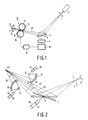
- An X-ray analysis apparatus as shown in Fig. 1 comprises an X-ray source 1, an object 5 which is arranged on a goniometer 3, and an X-ray detector 9 which is in this case provided with a detector entrance slit 7.
- the object can be rotated about a ⁇ -axis 6 by means of the goniometer.
- the X-ray source 1 is, for example an X-ray tube, the object being a specimen or a monochromator crystal to be analysed; the X-ray detector may be formed by a scintillation detector, a gas ionization detector, a combination thereof or possibly by a multi-channel position-sensitive semiconductor detector.
- an adjustable divergence slit 11 which is formed in accordance with the invention by a lamination 13 which is rotatable about a shaft 12 and a lamination 15 which is rotatable about a shaft 14.
- the shafts 12 and 14 extend parallel to one another and parallel to the ⁇ -axis 6, and hence perpendicularly to a radiation vector 20 and parallel to an object surface to be irradiated.
- the laminations 13 and 15 constitute parts of cylinders which have, for example a radius of approximately 5 mm and a length of approximately 10 mm and extend, for example, from 120° to 180° about the shafts 12 and 14.
- the laminations are preferably made of a material having a comparatively high X-ray absorption, for example brass, chromium, tungsten and the like.
- a portion 19 of an X-ray beam 18 to be emitted by the X-ray source 1 is transmitted in the position of the diaphragm shown (see also Fig. 2).
- the X-ray beam is in this case substantially symmetrical about the radiation vector 20 which connects a centre of the focus to a centre of the object.
- the beam may also deviate substantially from said symmetry.
- the focus, and hence the X-ray beam, is linear in practical cases with a longitudinal axis extending perpendicularly to the plane of drawing. Movements in the goniometer and for the slits can be executed by a motor-drive system 8 controlled by a control mechanism 10.
- Interrupted lines in Fig. 2 denote a radiation beam for a smaller angle of incidence ⁇ where the diaphragm has been closed further for irradiation of the same surface area, in this case exactly the entire irradiated surface of the object, so that a beam 19' is transmitted via a smaller aperture.
- the Figure diagrammatically shows drive motors 30 and 32 which serve to drive the diaphragm laminations and each of which is provided with an encoder 34, 36, or is constructed as a step motor.
- a corresponding drive motor 38 with an encoder 40 for the ⁇ -axis is also shown.
- the three motors can be coupled via the encoders and the motor position as well as the control of each of the motors can be controlled. Such a control can be performed independently or directly coupled for each of the motors.
- motors can be coupled, for example mechanically. In that case the control system 10 acts more or less as a measuring system for detecting the position of the motors.
- the drive motor for the ⁇ -angle is coupled to a first motor of the diaphragm system merely via encoding, a second motor being mechanically coupled to the first diaphragm motor.
- a more flexible system couples all three motors exclusively via encoding.
- mechanically coupled motors use can also be made of a single motor for several drives. If coupling is realised only via encoding, it is more practical to use separate motors.
- laminations of the described embodiment are identical. However, use can also be made of mutually different laminations, for example laminations having a different radius so that asymmetry in the beam path, for example due to a difference in distance between the front and the rear of the object, viewed along the beam path, can be compensated for.
- An embodiment of a diaphragm system as shown in Fig. 3 is an example of the construction of an adjustable slit diaphragm with a first lamination 13 and a second lamination 15 which are shown as separate parts for the sake of clarity.
- Both laminations constitute envelope portions, for example amounting to slightly less than 180°, of cylinders which are rotatable about shafts 12 and 14, respectively, via bushes 50 and coupling pieces 52.
- the laminations can be mounted in a diaphragm housing 55 by means of the coupling pieces 52 so that the axis of rotation 12 of the lamination 13 coincides with the centre of apertures 56 in the housing, and that the axis of rotation 14 of the lamination 15 coincides with the centre of apertures 58 in the housing, a concave side of the lamination 13 facing an incident X-ray beam 19 whilst the lamination 15 faces said beam by way of a convex side.
- a first drive motor 30 is axially coupled to the rotary shaft 12, via a coupling piece 60, a spring member 62 and a support 64, a second drive motor 32 being axially coupled to the rotary shaft 14, via a coupling piece 66, a spring member 68 and a support 70.
- the spring members 62 and 68 can with a sufficient accuracy of the construction parts also be omitted.
- the shaft 14 of the lamination 15 is rigidly coupled to the diaphragm housing 55, the shaft 12 of the lamination 13 being coupled to the housing via resilient journals 72 so that it can be adjustedly mounted parallel to the lamination 15 at a strictly defined distance therefrom.
- the lamination 13 may also be rigidly mounted and the lamination 15 may be mounted so as to be resilient.
- the housing 55, the spring members 62 and 68, and the supports 64 and 70 can be rigidly mounted in the analysis apparatus; in practical cases, all these elements are rigidly connected to the housing 55 and are mounted in the goniometer housing of the apparatus as one unit.
- the motors as such, and hence the drive shafts for the laminations thereof, are thus coupled to the housing via resilient journals 74 and 76, thus avoiding non-parallelism with respect to the ⁇ -axis and also wear during rotation but the drive shafts can also be rigidly coupled.
Landscapes
- Physics & Mathematics (AREA)
- Chemical & Material Sciences (AREA)
- General Physics & Mathematics (AREA)
- Immunology (AREA)
- Life Sciences & Earth Sciences (AREA)
- Analytical Chemistry (AREA)
- Biochemistry (AREA)
- General Health & Medical Sciences (AREA)
- Crystallography & Structural Chemistry (AREA)
- Health & Medical Sciences (AREA)
- Pathology (AREA)
- Spectroscopy & Molecular Physics (AREA)
- Engineering & Computer Science (AREA)
- General Engineering & Computer Science (AREA)
- High Energy & Nuclear Physics (AREA)
- Analysing Materials By The Use Of Radiation (AREA)
- X-Ray Techniques (AREA)
Applications Claiming Priority (2)
| Application Number | Priority Date | Filing Date | Title |
|---|---|---|---|
| NL8903044A NL8903044A (nl) | 1989-12-12 | 1989-12-12 | Roentgen analyse apparaat met een instelbaar spleetdiafragma. |
| NL8903044 | 1989-12-12 |
Publications (2)
| Publication Number | Publication Date |
|---|---|
| EP0432844A1 true EP0432844A1 (de) | 1991-06-19 |
| EP0432844B1 EP0432844B1 (de) | 1995-03-15 |
Family
ID=19855771
Family Applications (1)
| Application Number | Title | Priority Date | Filing Date |
|---|---|---|---|
| EP90203223A Expired - Lifetime EP0432844B1 (de) | 1989-12-12 | 1990-12-07 | Röntgenanalysegerät mit einstellbarer Schlitzblende |
Country Status (5)
| Country | Link |
|---|---|
| US (1) | US5115460A (de) |
| EP (1) | EP0432844B1 (de) |
| JP (1) | JP2941065B2 (de) |
| DE (1) | DE69017857T2 (de) |
| NL (1) | NL8903044A (de) |
Cited By (1)
| Publication number | Priority date | Publication date | Assignee | Title |
|---|---|---|---|---|
| CN103808745A (zh) * | 2014-01-24 | 2014-05-21 | 杭州电子科技大学 | 一种实现小角x射线衍射功能的装置及方法 |
Families Citing this family (6)
| Publication number | Priority date | Publication date | Assignee | Title |
|---|---|---|---|---|
| US6417605B1 (en) * | 1994-09-16 | 2002-07-09 | Micron Technology, Inc. | Method of preventing junction leakage in field emission devices |
| JP3989836B2 (ja) * | 2000-11-20 | 2007-10-10 | コーニンクレッカ フィリップス エレクトロニクス エヌ ヴィ | サンプル状態検査装置及び方法 |
| JP4278108B2 (ja) * | 2006-07-07 | 2009-06-10 | 株式会社リガク | 超小角x線散乱測定装置 |
| EP4524555A3 (de) * | 2018-04-13 | 2025-05-21 | Malvern Panalytical B.V. | Vorrichtung und verfahren zur röntgenanalyse mit hybrider steuerung der strahldivergenz |
| EP3719484B1 (de) * | 2019-04-04 | 2024-02-14 | Malvern Panalytical B.V. | Röntgenstrahlformungsvorrichtung und -verfahren |
| JP7492261B2 (ja) * | 2021-01-29 | 2024-05-29 | 株式会社リガク | X線分析装置 |
Citations (4)
| Publication number | Priority date | Publication date | Assignee | Title |
|---|---|---|---|---|
| GB1067144A (en) * | 1963-02-11 | 1967-05-03 | Picker X Ray Corp Waite Mfg | Improvements relating to beam delineators |
| US4380820A (en) * | 1980-06-19 | 1983-04-19 | The Machlett Laboratories, Incorporated | Compact X-ray collimator |
| DE3604935A1 (de) * | 1986-02-17 | 1987-08-20 | Siemens Ag | Blende mit kontinuierlich veraenderbarer wirksamer blendenoeffnung fuer diffraktometrische messeinrichtungen |
| EP0336473A1 (de) * | 1988-03-24 | 1989-10-11 | Koninklijke Philips Electronics N.V. | Röntgenuntersuchungsapparat mit einstellbarer schlitzförmiger Blende |
Family Cites Families (3)
| Publication number | Priority date | Publication date | Assignee | Title |
|---|---|---|---|---|
| US3852594A (en) * | 1973-07-25 | 1974-12-03 | Pepi Inc | X-ray diffraction apparatus |
| US4466112A (en) * | 1982-01-29 | 1984-08-14 | Technicare Corporation | Variable detector aperture |
| NL8201343A (nl) * | 1982-03-31 | 1983-10-17 | Philips Nv | Roentgen analyse apparaat met instelbare strooistralenspleet. |
-
1989
- 1989-12-12 NL NL8903044A patent/NL8903044A/nl not_active Application Discontinuation
-
1990
- 1990-12-07 EP EP90203223A patent/EP0432844B1/de not_active Expired - Lifetime
- 1990-12-07 DE DE69017857T patent/DE69017857T2/de not_active Expired - Fee Related
- 1990-12-10 JP JP2407221A patent/JP2941065B2/ja not_active Expired - Lifetime
- 1990-12-11 US US07/626,085 patent/US5115460A/en not_active Expired - Fee Related
Patent Citations (4)
| Publication number | Priority date | Publication date | Assignee | Title |
|---|---|---|---|---|
| GB1067144A (en) * | 1963-02-11 | 1967-05-03 | Picker X Ray Corp Waite Mfg | Improvements relating to beam delineators |
| US4380820A (en) * | 1980-06-19 | 1983-04-19 | The Machlett Laboratories, Incorporated | Compact X-ray collimator |
| DE3604935A1 (de) * | 1986-02-17 | 1987-08-20 | Siemens Ag | Blende mit kontinuierlich veraenderbarer wirksamer blendenoeffnung fuer diffraktometrische messeinrichtungen |
| EP0336473A1 (de) * | 1988-03-24 | 1989-10-11 | Koninklijke Philips Electronics N.V. | Röntgenuntersuchungsapparat mit einstellbarer schlitzförmiger Blende |
Cited By (2)
| Publication number | Priority date | Publication date | Assignee | Title |
|---|---|---|---|---|
| CN103808745A (zh) * | 2014-01-24 | 2014-05-21 | 杭州电子科技大学 | 一种实现小角x射线衍射功能的装置及方法 |
| CN103808745B (zh) * | 2014-01-24 | 2016-04-06 | 杭州电子科技大学 | 一种实现小角x射线衍射功能的方法 |
Also Published As
| Publication number | Publication date |
|---|---|
| JPH03251799A (ja) | 1991-11-11 |
| EP0432844B1 (de) | 1995-03-15 |
| DE69017857D1 (de) | 1995-04-20 |
| NL8903044A (nl) | 1991-07-01 |
| DE69017857T2 (de) | 1996-01-11 |
| JP2941065B2 (ja) | 1999-08-25 |
| US5115460A (en) | 1992-05-19 |
Similar Documents
| Publication | Publication Date | Title |
|---|---|---|
| US9194827B2 (en) | Scanning device using radiation beam for backscatter imaging and method thereof | |
| CA2823121C (en) | Scanning device and method for back-scatter imaging with a radiation beam | |
| CN111735828A (zh) | X射线分析装置 | |
| US5054041A (en) | High precision x-ray collimator | |
| US7123686B2 (en) | Apparatus and method for X-ray analysis | |
| EP0432844B1 (de) | Röntgenanalysegerät mit einstellbarer Schlitzblende | |
| EP0091150B1 (de) | Röntgenuntersuchungsgerät mit einstellbarer Schlitzverminderung von Streustrahlen | |
| US5268953A (en) | X-ray analysis apparatus including goniometer with angle encoders | |
| EP0336473B1 (de) | Röntgenuntersuchungsapparat mit einstellbarer schlitzförmiger Blende | |
| US5060247A (en) | Fluorescent x-ray film thickness gauge | |
| EP0137547B1 (de) | Zweikristall-Röntgenspektrometer | |
| US3728541A (en) | X-ray diffractometer | |
| US4199678A (en) | Asymmetric texture sensitive X-ray powder diffractometer | |
| US5898752A (en) | X-ray analysis apparatus provided with a double collimator mask | |
| JP3245475B2 (ja) | Exafs測定装置 | |
| EP0118932B1 (de) | Röntgenanalysegerät | |
| US6310937B1 (en) | X-ray diffraction apparatus with an x-ray optical reference channel | |
| US3344274A (en) | Ray analysis apparatus having both diffraction amd spectrometer tubes mounted on a common housing | |
| EP0120535B1 (de) | Strahlbelichtungsgerät mit einer Diaphragma-Bewegungsübertragung für den Objekthalter | |
| US3628015A (en) | Scanning mechanism for use in an x-ray spectrometer | |
| US3200248A (en) | Apparatus for use as a goniometer and diffractometer | |
| GB2098320A (en) | Measuring the thickness of a film on a member | |
| CN108459036B (zh) | X射线光学装置 | |
| US3427451A (en) | X-ray diffractometer having several detectors movable on a goniometer circle | |
| JPS6338438A (ja) | X線ct装置 |
Legal Events
| Date | Code | Title | Description |
|---|---|---|---|
| PUAI | Public reference made under article 153(3) epc to a published international application that has entered the european phase |
Free format text: ORIGINAL CODE: 0009012 |
|
| AK | Designated contracting states |
Kind code of ref document: A1 Designated state(s): DE FR GB |
|
| 17P | Request for examination filed |
Effective date: 19911216 |
|
| 17Q | First examination report despatched |
Effective date: 19940208 |
|
| GRAA | (expected) grant |
Free format text: ORIGINAL CODE: 0009210 |
|
| AK | Designated contracting states |
Kind code of ref document: B1 Designated state(s): DE FR GB |
|
| REF | Corresponds to: |
Ref document number: 69017857 Country of ref document: DE Date of ref document: 19950420 |
|
| ET | Fr: translation filed | ||
| PLBE | No opposition filed within time limit |
Free format text: ORIGINAL CODE: 0009261 |
|
| STAA | Information on the status of an ep patent application or granted ep patent |
Free format text: STATUS: NO OPPOSITION FILED WITHIN TIME LIMIT |
|
| 26N | No opposition filed | ||
| REG | Reference to a national code |
Ref country code: FR Ref legal event code: CD |
|
| PGFP | Annual fee paid to national office [announced via postgrant information from national office to epo] |
Ref country code: GB Payment date: 20001220 Year of fee payment: 11 |
|
| PGFP | Annual fee paid to national office [announced via postgrant information from national office to epo] |
Ref country code: FR Payment date: 20001226 Year of fee payment: 11 |
|
| PGFP | Annual fee paid to national office [announced via postgrant information from national office to epo] |
Ref country code: DE Payment date: 20010214 Year of fee payment: 11 |
|
| PG25 | Lapsed in a contracting state [announced via postgrant information from national office to epo] |
Ref country code: GB Free format text: LAPSE BECAUSE OF NON-PAYMENT OF DUE FEES Effective date: 20011207 |
|
| REG | Reference to a national code |
Ref country code: GB Ref legal event code: IF02 |
|
| PG25 | Lapsed in a contracting state [announced via postgrant information from national office to epo] |
Ref country code: DE Free format text: LAPSE BECAUSE OF NON-PAYMENT OF DUE FEES Effective date: 20020702 |
|
| GBPC | Gb: european patent ceased through non-payment of renewal fee |
Effective date: 20011207 |
|
| PG25 | Lapsed in a contracting state [announced via postgrant information from national office to epo] |
Ref country code: FR Free format text: LAPSE BECAUSE OF NON-PAYMENT OF DUE FEES Effective date: 20020830 |
|
| REG | Reference to a national code |
Ref country code: FR Ref legal event code: ST |