EP0432996B1 - Vorrichtung zur Bestätigung der Abgabe von Münzen - Google Patents
Vorrichtung zur Bestätigung der Abgabe von Münzen Download PDFInfo
- Publication number
- EP0432996B1 EP0432996B1 EP19900313396 EP90313396A EP0432996B1 EP 0432996 B1 EP0432996 B1 EP 0432996B1 EP 19900313396 EP19900313396 EP 19900313396 EP 90313396 A EP90313396 A EP 90313396A EP 0432996 B1 EP0432996 B1 EP 0432996B1
- Authority
- EP
- European Patent Office
- Prior art keywords
- coin
- electric element
- piezo
- release
- machine
- Prior art date
- Legal status (The legal status is an assumption and is not a legal conclusion. Google has not performed a legal analysis and makes no representation as to the accuracy of the status listed.)
- Expired - Lifetime
Links
- 238000012795 verification Methods 0.000 title claims description 10
- 230000007246 mechanism Effects 0.000 claims description 24
- 230000007257 malfunction Effects 0.000 claims description 4
- 239000003990 capacitor Substances 0.000 description 4
- 239000000463 material Substances 0.000 description 4
- 239000000853 adhesive Substances 0.000 description 2
- 230000001070 adhesive effect Effects 0.000 description 2
- 230000000694 effects Effects 0.000 description 2
- 230000001052 transient effect Effects 0.000 description 2
- 239000012790 adhesive layer Substances 0.000 description 1
- 238000010586 diagram Methods 0.000 description 1
- 238000002955 isolation Methods 0.000 description 1
- 239000000126 substance Substances 0.000 description 1
Images


Classifications
-
- G—PHYSICS
- G07—CHECKING-DEVICES
- G07D—HANDLING OF COINS OR VALUABLE PAPERS, e.g. TESTING, SORTING BY DENOMINATIONS, COUNTING, DISPENSING, CHANGING OR DEPOSITING
- G07D1/00—Coin dispensers
-
- G—PHYSICS
- G07—CHECKING-DEVICES
- G07D—HANDLING OF COINS OR VALUABLE PAPERS, e.g. TESTING, SORTING BY DENOMINATIONS, COUNTING, DISPENSING, CHANGING OR DEPOSITING
- G07D5/00—Testing specially adapted to determine the identity or genuineness of coins, e.g. for segregating coins which are unacceptable or alien to a currency
Definitions
- This invention relates to verifying the release of coins by machines.
- Vending machines may be equipped to release coins in order to give change.
- Gaming machines may release coins as prizes.
- Machines may be constructed to dispense coins of one denomination in exchange for notes or coins of a different denomination.
- Mechanisms to effect the release of a coin from a quantity of coins are known.
- a pay-slide mechanism is known for this purpose.
- a vertical tube holds a stack of coins.
- a plate which supports the coins but has a cavity able to accommodate a single coin from the bottom of the stack.
- the plate is attached to a solenoid which, when energised causes rapid movement of the plate. Because the plate has a cavity able to accommodate a single coin, the movement of the plate has the effect of displacing the bottom coin from the stack into a position from which it can fall or roll, e.g. down a chute, to a place where it is accessible to the intended recipient.
- DE-A-3121446 describes a coin counting device having a pusher which pushes a coin out from the bottom of a stack of coins, the coin displacing a counting arm positioned in the coin release chute as it is pushed from the stack, thereby providing a means for counting the coins.
- the present invention seeks to provide for the verification of coin release in a manner which is simple and inexpensive to implement.
- a machine which incorporates a coin release mechanism, a machine control system which initiates operation of the coin release mechanism, and coin release verification means for detecting any malfunction of the coin release mechanism wherein operation thereof fails to release a coin
- the verification means comprising a piezo-electric element positioned to be struck by a coin after release thereof, and circuitry electrically connected to the piezo-electric element to provide an electrical signal to the control system when a released coin strikes the piezo electric element to verify that the operation of the coin release mechanism has released a coin.
- the piezo electric element is laminar in shape: it may for example be provided by a thin square or rectangle of material having piezo electric properties. Such material is available from Pennwalt Piezo Film Limited, Dunfermline, Scotland.
- the piezo electric element may be held by a resiliently deformable support which itself is attached to the structure of the machine.
- a resiliently deformable carrier between the piezo electric element itself and the rigid structure of the machine can help to isolate the piezo electric element from vibration and enable it to be more responsive to impact from a released coin.
- Circuitry to which the piezo electric element is connected must serve to generate an output signal when a coin strikes the piezo electric element.
- This output signal can then be used by a control mechanism of the machine.
- the signal might be used in various ways as may be desired for the operation of the whole machine.
- One simple possibility would be to arrange that (i) when the control mechanism of the machine caused the release of coin, for example by energising the solenoid of the release mechanism, it also caused an indicator lamp to light, (ii) the signal from the piezo electric element and its associated circuitry caused the indicator lamp to go out. In the event of proper functioning of the machine the indicator lamp would not remain alight when the coin was released. If the indicator lamp did remain alight it would indicate a malfunction.
- the circuitry connected to the piezo electric element may take various forms.
- a preferred possibility which has the advantage of requiring only a fairly small number of components utilises an operational amplifier connected to give decaying positive feedback.
- the pulse produced by the piezo electric element when struck by a coin is processed by the operational amplifier and the amount of positive feedback serves to determine the length of the generated pulse from the operational amplifier.
- the resulting signal, processed and shaped by means of the operating amplifier could then serve as an input to logic circuitry.
- the pay-slide has a tube 10 to contain a vertical stack of coins 12.
- a plate 14 which acts as a stop to prevent coins falling from the tube.
- This plate 14 is part of a bracket 16 on which is mounted a solenoid 18.
- the plate 14 is spaced slightly below the bottom of the tube 10 and a plunger 20 is shaped so as to project into the gap between the plate 14 and the tube 10.
- the plunger constitutes the armature of the solenoid 18 or is connected to the armature.
- the plunger is urged towards the position illustrated by a spring.
- the solenoid 18 When the solenoid 18 is energised the plunger is drawn to the left into the solenoid against the reaction of the spring.
- the stack of coins normally rests on top of the finger 22 which projects from the plunger 20.
- the solenoid 18 is energised pulling the plunger 20 to the left and pulling out the finger 22 from beneath the bottom coin of the stack.
- the stack drops until the bottom coin rests on the stop 14.
- the solenoid is de-energised the plunger returns and the finger 22 pushes the bottom coin (but only the bottom coin) to the right.
- the coin strikes an end wall 26 as shown by the coin drawn in chain-dotted lines at the position indicated as 24.
- the coin then falls further as indicated by the coin shown in chain lines at 28 into a chute (not shown) which guides the falling coin to a tray from which it can be picked up by the user.
- the pay-slide mechanism is a conventional one.
- a laminar piece of piezo electric film 30 is attached to the end wall 26 so that it will be struck by a released coin when the coin strikes the end wall as is illustrated at the position 24.
- the piezo electric film may be attached by an adhesive layer on its rear surface.
- the piezo electric film 30 is attached to the end wall 26 of the pay-slide mechanism by means of a piece 32 of double-sided adhesive material. This piece is somewhat resilient and provides some isolation of the piezo electric element from mechanical vibration. Connections to the piezo electric element 30 are connectors crimped to it at two spaced apart positions, one behind the plane of Fig. 1 and one in front of the plane of Fig. 1.
- the electrical circuit which is used to obtain a useful signal from the piezo electric element is shown in Fig. 3.
- the piezo electric element 30 is connected to the non-inverting input of an operational amplifier 34.
- the inverting input of the operational amplifier is held at a constant voltage by the resistors R1 and R2.
- the output from the operational amplifier is connected back to the non-inverting input via capacitor C1. That input is also connected to ground through capacitor C2 and resistor R3.
- the input of the operational amplifier is held at ground through the resistor R3.
- a coin strikes a piezo electric element it produces a transient voltage which is amplified by the operational amplifier.
- the connection to the non-inverting input through capacitor C1 gives positive feedback so the initial transient voltage generated by the piezo electric element is processed to provide a lengthened output pulse.
- the length of the output pulse is determined by the time taken to return the non-inverting input of the operational amplifier to ground.
- the output from this circuit on line 36 is a square wave pulse which can be used by the controls of the machine. The presence of this output pulse at the appropriate time confirms that a coin actually has been pushed off the bottom of the stack in the tube 10 so as to strike the end wall 26.
- the present invention thus provides verification while only requiring the addition of the piezo electric element (and possibly double-sided adhesive material) to the conventional pay-slide mechanism and requiring only a simple circuit to convert the output from the piezo electric element itself into a useful electrical signal.
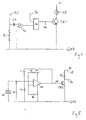
- Fig. 4 illustrates by way of example a possible and simple circuit to make use of the verification.
- the signal on line 40 to energise the relay 18 is coupled through capacitor C4 and Schmitt trigger 42 to one input of an RS flip flop 44. This sends line 46 high, causing transistor TR1 to light lamp 48.
- the signal on line 36 of Fig. 3 could, if desired be amplified and inverted as shown in Fig. 5.
- the line 36 is connected to the base of transistor TR2.
- a positive signal on line 36 increases collector current at transistor TR2, so increasing the voltage drop across R4 and hence producing an amplified but inverted signal on line 56.
- the supply on line 58 is not the supply voltage V + but a high frequency square wave signal such as the clock pulse of a control circuit. The presence of a signal on line 36 would then lead to the output of a square wave on line 56, for the duration of the signal on line 36.
- An output signal such as produced on line 36 of Fig. 3 or line 56 of Fig. 5 could be used as input to forms of circuitry other than the outer simple circuit of Fig. 4. It could well serve as input to more elaborate control circuitry of a machine, for this circuitry to making use of the verification signal.
- the invention would also be applicable to other mechanisms for releasing a coin. All that is necessary to implement the invention is to position the piezo electric film where it will be struck reliably by a coin as the coin is released.
Landscapes
- Physics & Mathematics (AREA)
- General Physics & Mathematics (AREA)
- Control Of Vending Devices And Auxiliary Devices For Vending Devices (AREA)
Claims (6)
- Vorrichtung bzw. Maschine, die einen Münzenfreigabemechanismus, ein Vorrichtungssteuerungssystem, das den Betrieb des Münzenfreigabemechanismus in Gang setzt, und Münzenfreigabeverifizierungsmittel zum Ermitteln jeglicher Fehlfunktion des Münzenfreigabemechanismus umfaßt, bei der durch seinen Betrieb keine Münze freigegeben wird, wobei das Verifizierungsmittel ein piezoelektrisches Element (30) umfaßt, das so angeordnet ist, daß es von einer Münze (24) nach deren Freigabe getroffen wird, sowie eine Schaltung, die elektrisch mit dem piezoelektrischen Element (30) verbunden ist, um an das Steuerungssystem ein elektrisches Signal abzugeben, wenn eine freigegebene Münze (24) das piezoelektrische Element (30) trifft, um zu verifizieren, daß durch den Betrieb des Münzenfreigabemechanismus eine Münze freigegeben worden ist.
- Vorrichtung nach Anspruch 1, worin die Schaltung einen Operationsverstärker (34) umfaßt, der so angeschlossen ist, daß er eine abklingende positive Rückkopplung ergibt.
- Vorrichtung nach Anspruch 1 oder 2, worin die Schaltung ein RS-Flipflop (44) umfaßt, das so angeschlossen ist, daß es vom Operationsverstärker ein Signal empfängt.
- Vorrichtung nach einem der vorangegangenen Ansprüche, worin das piezoelektrische Element (30) lamellenförmig ist.
- Vorrichtung nach einem der vorangegangenen Ansprüche, worin das piezoelektrische Element (30) von einer elastisch verformbaren Stütze (32) gehalten wird, die wiederum an einer starreren Struktur (26) des Vorrichtungs befestigt ist.
- Vorrichtung nach einem der vorangegangenen Ansprüche, worin der Mechanismus ein Zahleinwurf mit einer Röhre (10) zum Halten eines Münzenstapels (12) ist, die von einer Platte (14) mit einem Hohlraum für eine Münze vom Stapel geschlossen wird, und einem Betriebssolenoid (18), um die Platte (14) in eine Position zu bewegen, in der die Münze im Hohlraum freigegeben wird.
Applications Claiming Priority (2)
| Application Number | Priority Date | Filing Date | Title |
|---|---|---|---|
| GB898928256A GB8928256D0 (en) | 1989-12-14 | 1989-12-14 | Coin release verification |
| GB8928256 | 1989-12-14 |
Publications (2)
| Publication Number | Publication Date |
|---|---|
| EP0432996A1 EP0432996A1 (de) | 1991-06-19 |
| EP0432996B1 true EP0432996B1 (de) | 1996-07-24 |
Family
ID=10667935
Family Applications (1)
| Application Number | Title | Priority Date | Filing Date |
|---|---|---|---|
| EP19900313396 Expired - Lifetime EP0432996B1 (de) | 1989-12-14 | 1990-12-10 | Vorrichtung zur Bestätigung der Abgabe von Münzen |
Country Status (2)
| Country | Link |
|---|---|
| EP (1) | EP0432996B1 (de) |
| GB (1) | GB8928256D0 (de) |
Cited By (2)
| Publication number | Priority date | Publication date | Assignee | Title |
|---|---|---|---|---|
| US7191915B2 (en) | 1998-04-29 | 2007-03-20 | Automated Merchandising Systems Inc. | Optical vend-sensing system for control of vending machine |
| US8548625B2 (en) | 2001-08-23 | 2013-10-01 | Crane Merchandising Systems, Inc. | Optical vend sensing system for product delivery detection |
Families Citing this family (12)
| Publication number | Priority date | Publication date | Assignee | Title |
|---|---|---|---|---|
| GB2275532A (en) * | 1993-02-25 | 1994-08-31 | Mars Inc | Coin handling apparatus |
| GB9401040D0 (en) * | 1994-01-20 | 1994-03-16 | Starpoint Electrics Ltd | Payout apparatus |
| GB2290288A (en) * | 1994-06-08 | 1995-12-20 | Thomas Nicolaas Antonius Tol | A coin dispensing device |
| JPH08123987A (ja) * | 1994-10-28 | 1996-05-17 | Tec Corp | 硬貨収納払出し装置 |
| GB2305866B (en) * | 1995-10-03 | 1999-06-23 | Cromptons Leisure Mach Ltd | Amusement machine |
| US6138813A (en) * | 1999-06-03 | 2000-10-31 | Mars, Incorporated | Coin mechanism with a piezoelectric film sensor |
| US6732014B2 (en) | 2001-02-27 | 2004-05-04 | Crane Co. | System for accomplishing product detection |
| US7286901B2 (en) * | 2001-02-27 | 2007-10-23 | Crane Co. | Method and system for accomplishing product detection |
| US6708079B2 (en) | 2001-06-01 | 2004-03-16 | Automated Merchandising Systems | Optical vend-sensing system for control of vending machine |
| US20030024790A1 (en) * | 2001-07-31 | 2003-02-06 | Quattrini Victor A. | Apparatus for monitoring coins discharged from a coi dispenser |
| AU2002349919B2 (en) | 2001-10-24 | 2008-11-13 | Crane Co. | Apparatus and methodology of detecting fulfillment of customer vend request |
| US7565222B2 (en) | 2004-01-15 | 2009-07-21 | Fawn Engineering Corporation | Economical optical system to provide reasonable assurance of completed vend or vendible items from vending machines |
Family Cites Families (8)
| Publication number | Priority date | Publication date | Assignee | Title |
|---|---|---|---|---|
| GB2043317B (en) * | 1979-03-01 | 1983-03-23 | Mars Inc | Coin dispenser |
| CH645201A5 (en) * | 1980-03-10 | 1984-09-14 | Sodeco Compteurs De Geneve | Method and device for testing the authenticity of coins |
| JPS57274U (de) * | 1980-05-30 | 1982-01-05 | ||
| DK327581A (da) * | 1981-07-23 | 1983-01-24 | Gnt Automatic As | Fremgangsmaade til klasseficering af moenter i henhold til deres mekaniske elasticitet |
| GB2168185B (en) * | 1984-12-05 | 1987-09-23 | Mars Inc | Checking coins |
| GB8518206D0 (en) * | 1985-07-19 | 1985-08-29 | Hearn W C | Coin operated machine cash control |
| DE3526378A1 (de) * | 1985-07-24 | 1987-02-05 | Andras Dipl Ing Gati | Vorrichtung mit einem sensor zur erkennung von muenzen |
| GB8623054D0 (en) * | 1986-09-25 | 1986-10-29 | Bell Fruit Mfg Co Ltd | Dispensing coins |
-
1989
- 1989-12-14 GB GB898928256A patent/GB8928256D0/en active Pending
-
1990
- 1990-12-10 EP EP19900313396 patent/EP0432996B1/de not_active Expired - Lifetime
Cited By (3)
| Publication number | Priority date | Publication date | Assignee | Title |
|---|---|---|---|---|
| US7191915B2 (en) | 1998-04-29 | 2007-03-20 | Automated Merchandising Systems Inc. | Optical vend-sensing system for control of vending machine |
| US7742837B2 (en) | 1998-04-29 | 2010-06-22 | Automated Merchandising Systems Inc. | Optical vend-sensing system for control of vending machine |
| US8548625B2 (en) | 2001-08-23 | 2013-10-01 | Crane Merchandising Systems, Inc. | Optical vend sensing system for product delivery detection |
Also Published As
| Publication number | Publication date |
|---|---|
| EP0432996A1 (de) | 1991-06-19 |
| GB8928256D0 (en) | 1990-02-21 |
Similar Documents
| Publication | Publication Date | Title |
|---|---|---|
| EP0432996B1 (de) | Vorrichtung zur Bestätigung der Abgabe von Münzen | |
| EP0184393B1 (de) | Münzprüfvorrichtung | |
| US5496212A (en) | Coin sorting device | |
| US2581502A (en) | Coin changer | |
| US5137134A (en) | Vending machine for newspapers and magazines | |
| US3776338A (en) | Credit pulse generating system for vending machines | |
| US20030024790A1 (en) | Apparatus for monitoring coins discharged from a coi dispenser | |
| GB851100A (en) | A coin-operated automatic vending machine for dispensing individually selectable goods suspended in the machine | |
| EP0343967B1 (de) | Weichenvorrichtung für münzbetriebene Maschinen | |
| US1637710A (en) | Check-dispensing machine | |
| US2810465A (en) | miller | |
| US1398283A (en) | Vending-machine | |
| JP3065413B2 (ja) | 弾球遊技機 | |
| US2561880A (en) | Coin and check separator | |
| ES478135A1 (es) | Perfeccionamientos en conjuntos electromagneticos de distri-bucion de premios para maquinas tragaperras. | |
| US3319822A (en) | Vending machine discharge means | |
| US2286321A (en) | Apparatus for separating genuine | |
| US3849783A (en) | Time recorder | |
| GB1238997A (de) | ||
| US2335369A (en) | Apparatus for separating genuine from spurious coins | |
| EP0116215B1 (de) | Füllhöhenanzeiger für Münzen | |
| US3791505A (en) | Solid state vend control means and process of operation | |
| JPH0615030A (ja) | パチンコ機 | |
| GB2199312A (en) | Solenoid operated payout unit | |
| US929733A (en) | Vending-machine. |
Legal Events
| Date | Code | Title | Description |
|---|---|---|---|
| PUAI | Public reference made under article 153(3) epc to a published international application that has entered the european phase |
Free format text: ORIGINAL CODE: 0009012 |
|
| AK | Designated contracting states |
Kind code of ref document: A1 Designated state(s): GB NL |
|
| 17P | Request for examination filed |
Effective date: 19911209 |
|
| 17Q | First examination report despatched |
Effective date: 19930901 |
|
| GRAH | Despatch of communication of intention to grant a patent |
Free format text: ORIGINAL CODE: EPIDOS IGRA |
|
| GRAH | Despatch of communication of intention to grant a patent |
Free format text: ORIGINAL CODE: EPIDOS IGRA |
|
| GRAA | (expected) grant |
Free format text: ORIGINAL CODE: 0009210 |
|
| AK | Designated contracting states |
Kind code of ref document: B1 Designated state(s): GB NL |
|
| RAP1 | Party data changed (applicant data changed or rights of an application transferred) |
Owner name: MAYGAY MACHINES LIMITED |
|
| PLBE | No opposition filed within time limit |
Free format text: ORIGINAL CODE: 0009261 |
|
| STAA | Information on the status of an ep patent application or granted ep patent |
Free format text: STATUS: NO OPPOSITION FILED WITHIN TIME LIMIT |
|
| 26N | No opposition filed | ||
| PGFP | Annual fee paid to national office [announced via postgrant information from national office to epo] |
Ref country code: GB Payment date: 20011130 Year of fee payment: 12 |
|
| REG | Reference to a national code |
Ref country code: GB Ref legal event code: IF02 |
|
| PG25 | Lapsed in a contracting state [announced via postgrant information from national office to epo] |
Ref country code: GB Free format text: LAPSE BECAUSE OF NON-PAYMENT OF DUE FEES Effective date: 20021210 |
|
| GBPC | Gb: european patent ceased through non-payment of renewal fee | ||
| PGFP | Annual fee paid to national office [announced via postgrant information from national office to epo] |
Ref country code: NL Payment date: 20031219 Year of fee payment: 14 |
|
| PG25 | Lapsed in a contracting state [announced via postgrant information from national office to epo] |
Ref country code: NL Free format text: LAPSE BECAUSE OF NON-PAYMENT OF DUE FEES Effective date: 20050701 |
|
| NLV4 | Nl: lapsed or anulled due to non-payment of the annual fee |
Effective date: 20050701 |