EP0433164B1 - Wärmeisolierendes und feuerhemmendes Wandpaneel - Google Patents
Wärmeisolierendes und feuerhemmendes Wandpaneel Download PDFInfo
- Publication number
- EP0433164B1 EP0433164B1 EP90403532A EP90403532A EP0433164B1 EP 0433164 B1 EP0433164 B1 EP 0433164B1 EP 90403532 A EP90403532 A EP 90403532A EP 90403532 A EP90403532 A EP 90403532A EP 0433164 B1 EP0433164 B1 EP 0433164B1
- Authority
- EP
- European Patent Office
- Prior art keywords
- panel
- bent
- panel according
- core
- panels
- Prior art date
- Legal status (The legal status is an assumption and is not a legal conclusion. Google has not performed a legal analysis and makes no representation as to the accuracy of the status listed.)
- Expired - Lifetime
Links
Images



Classifications
-
- E—FIXED CONSTRUCTIONS
- E04—BUILDING
- E04C—STRUCTURAL ELEMENTS; BUILDING MATERIALS
- E04C2/00—Building elements of relatively thin form for the construction of parts of buildings, e.g. sheet materials, slabs, or panels
- E04C2/02—Building elements of relatively thin form for the construction of parts of buildings, e.g. sheet materials, slabs, or panels characterised by specified materials
- E04C2/26—Building elements of relatively thin form for the construction of parts of buildings, e.g. sheet materials, slabs, or panels characterised by specified materials composed of materials covered by two or more of groups E04C2/04, E04C2/08, E04C2/10 or of materials covered by one of these groups with a material not specified in one of the groups
- E04C2/284—Building elements of relatively thin form for the construction of parts of buildings, e.g. sheet materials, slabs, or panels characterised by specified materials composed of materials covered by two or more of groups E04C2/04, E04C2/08, E04C2/10 or of materials covered by one of these groups with a material not specified in one of the groups at least one of the materials being insulating
- E04C2/292—Building elements of relatively thin form for the construction of parts of buildings, e.g. sheet materials, slabs, or panels characterised by specified materials composed of materials covered by two or more of groups E04C2/04, E04C2/08, E04C2/10 or of materials covered by one of these groups with a material not specified in one of the groups at least one of the materials being insulating composed of insulating material and sheet metal
Definitions
- the invention relates to an insulating and fire-resistant partition panel.
- Panels of this type are already known which generally comprise a sandwich structure formed from a rock wool core comprised between two facings.
- Such a panel is produced by pouring hot and vacuum molten glass foam between the two facing faces arranged opposite.
- This casting operation must be done at a temperature of about 800 ° C, so that it is impossible to use panels already provided with a coating.
- an internal coating for example aluminum, must be provided on the facings to facilitate the bonding of the facings with the glass foam.
- an insulating panel comprising an insulating core between two facings.
- this insulating core is not made of glass foam and therefore does not make it possible to obtain the insulating characteristics of the latter.
- the invention relates more particularly to an insulating and fire-resistant partitioning panel of the type described in US-A-4,024,309.
- This panel is characterized in that the core is formed from adjacent glass foam blocks and in that the glass foam core is bonded to the two facings by a two-component polyurethane adhesive.
- glass foam means to design cellular glass with closed pores which is usually in the form of blocks.
- the metal sheet of the facings for example steel or aluminum, optionally comprises an external coating, for example a pre-lacquering or a plastic coating of the PVC type.
- each of the facings is a metal sheet half-shell comprising a rectangular flat plate which has, on its four sides, edges folded towards the edge of the panel.
- two respective folded edges of the two half-shells, situated on the same side of the panel constitute means for assembling the panel to an adjacent panel.
- assembly means are provided on the two vertical sides of the same panel.
- each of the folded edges comprises a first part perpendicular to the plate and folded over the edge of the panel, of width less than half the thickness of the core, a second folded part perpendicular to the first part and a third part folded perpendicular to the second, the two folded edges located on the same side of the panel being adapted to cooperate with the two folded edges homologous of an adjacent panel to receive two clips of U-section clipping each comprising a central core extending parallel to the plane of the panels and two wings each coming to bear against the first part of a folded edge, and this by means of a spring.
- the two respective folded edges of the two half-shells have a first part folded towards the edge of the panel and a second part folded parallel to the plane of the panel so as to form a male-type casing element.
- an insulating seal is bonded between the respective second parts of the folded edges to form a tongue, and this without creating thermal or phonic bridges between the two half-shells.
- the two respective folded edges of the two half-shells have a first part folded towards the edge and a second part folded in the thickness of the glass foam to form a casing element of the female type.
- This female casing element can cooperate with a male element as defined above.
- each facing is a metal sheet extending over the entire surface of the panel.
- the sheet does not have folded edges as defined above.
- each panel comprises in its edge which extends on at least one side a groove suitable for receiving a false tongue with a generally rectangular section.
- the groove formed in the edge of the panel is advantageously defined by a sheet metal profile engaged in the thickness of the glass foam core.
- a fire-resistant seal is placed between two adjacent panels on either side of the false tongue.
- This false tongue is advantageously constituted by a section of generally rectangular section. It can be a solid profile or even a resistant hollow profile, in particular for the case of very high panels.
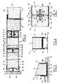
- FIG. 1 shows the assembly of two panels 10 according to the invention.
- Each panel 10 comprises a core 12 formed from blocks of glass foam, of the same thickness, bonded respectively to two facings 14.
- each facing 14 is a half-shell comprising a rectangular plate folded over its four sides.
- each of the half-shells is folded over its vertical sides to form a folded edge 16.
- Each folded edge 16 comprises a first part 18 folded at right angles in the edge of the panel and extending over a width less than the half-thickness of the core 12.
- the first part 18 is connected perpendicularly to a second part 20 parallel to the plane of the panels, which is connected perpendicularly to a third part 22 which extends over a small width.
- each profile comprises a central core 26 parallel to the plane of the panels and two wings 28 coming from each bearing against the first part 18 of a folded edge 16, and this by means of a spring 30.
- four springs 30 are used, which each enclose the second part 20 and the third part 22 with a folded edge 28.
- the panels 10 shown in Figure 1 may have, for example, a height of 2.50 meters to 3.50 meters and a width corresponding to a frame of 60 or 90 centimeters. In the example, the panels have a total thickness of 50 millimeters.
- FIG. 2 shows, in section, a partition comprising a partition panel 10 identical to those of Figure 1 and having a horizontal frame T.
- the panel 10 is assembled, by one of its vertical sides , on a junction element 34 constituted by a U-shaped profile having two folded edges 36 spaced from one another, of a configuration similar to that of the folded edges 16 of the panel.
- the element 34 is fixed by its wings to another joining element 38 constituted by a U-section profile.
- the element 38 has a core 40 which is fixed to a wall or a transverse partition 42 by means of screws 44.
- a lining 46 for example formed of alumina silicate fibers.
- the panel 10 is fixed to the junction element 34 by means of two clipping profiles 24 identical to those shown in FIG. 1.
- the opposite vertical side of the panel 10 is fixed, by means of two clipping profiles 24, to an upright of frame 48 having two folded edges 50 of the same configuration as that of the folded edges 16 of the panel 10.
- the amount 48 part of a frame 52 which includes another upright 54 also provided with two folded edges 53.
- the upright 48 includes hinges 56 for mounting a door 58 having a core 60 of glass foam.
- the uprights 48 and 54 also include a fire-resistant lining, for example based on alumina silicate fibers.
- the seal 55 is an isophonic polyethylene foam seal which is placed in the bottom of the rebate.
- the seal 57 is an intumescent seal which is located next to the seal 55 and close to the edge of the rebate, in a plane parallel to that of the door 58.
- the seal 57 is a hard seal which cannot be used as a shock absorber during closing the door.
- the seals 55 and 57 form a fire-resistant continuity between the door and the partition.
- the intumescent seal 57 increases in volume, for example quadruple in volume, and thus creates a seal at the bottom of the rebate.
- FIG. 3 shows the angled connection of two panels 10 according to the invention by means of a clipping profile 24 similar to those of Figures 1 and 2 and a clipping profile 62 forming return d 'angle.
- This profile 62 has the shape of an angle iron which is provided with a wing 64 of structure similar to the wing 28 of the profile 24 and with a folded edge 66 of configuration similar to that of a folded edge 16 of a panel 10.
- the wing 64 is clipped into the folded edge 16 of one of the panels 10, while its folded edge 66 cooperates with a folded edge 16 of the other panel 10 to receive the clipping profile 24.
- Mattresses 68 and 70 in insulating and fire-resistant material are disposed respectively in the profile 62 and the profile 24.
- two other mattresses 72 and 74 are provided inside the junction d 'angle.
- an X-shaped extruded seal 76 is provided, for example based on neoprene, or in extruded silicone.
- FIG. 4 shows a partition comprising a panel 80 according to the invention having a core 12 of glass foam and two plates 84 forming half-shells.
- the two plates 84 define folded edges 16 similar to those described above.
- the panel 80 is assembled on an upright of frame 48 similar to that of FIG. 2.
- This upright also comprises two folded edges 50 allowing the assembly of the panel 80 and the upright 48 by two profiles of clipping 24.
- the upright 48 is part of a frame 52 comprising a door 58 provided with a core 60 of glass foam.
- each edge 86 comprises a first part 88 forming, with the plane of the panel, an angle slightly less than 90 °, and a part 90 which s extends parallel to the plane of the panel.
- the two parts 90 are joined together to form a male element 92 in the form of a false tongue.
- the panel 80 cooperates with a panel 94 comprising two facings 96, in the form of half-shells, and a core 98 of glass foam.
- the facings 96 comprise two folded edges 100 each constituted by a first part 102 folded at a right angle and having a width less than the half thickness of the core 98 and a second part 104 which extends towards the inside of the panel.
- the two parts 104 define between them a housing for receiving the false tongue 92.
- the panel 94 On its opposite side, the panel 94 has two folded edges 86 similar to those of the panel 80.
- the panel 94 is fitted into a U-shaped joining profile 106, the core 108 of which is fixed to a partition 110.
- the half-shells 14 of the panel 10 form, in the lower part, two folded edges 112 which provide between them an empty space 114.
- the base of the panel 10 is fitted into a horizontal profile 116, with a cross-section U, which is fixed, by spot welds 118, to a metal floor 120.
- a layer 122 of a fire-resistant anti-vibration material is interposed between the bottom of the profile 116 and the base of the panel 10.
- a layer of a material 124 is placed on the floor 120 to smooth the floor.
- the two half-shells 14 of the panel 10 have, in the lower part, folded edges 126 which extend in the extension of the plane of the panel.
- the two edges 126 allow the base of the panel to be fitted onto a profile 128 welded to the floor 120.
- the profile 108 is a hollow profile of generally rectangular section split on one of its large bases to affect the general shape of an omega.
- FIG. 7 shows the assembly of two panels 130 according to the invention.
- Each panel includes a core 132 of glass foam glued to two sheet metal facings 134, for example of steel, by means of a layer of adhesive 136.
- the facings 134 forming half-shells, have folded edges 138 forming an angle close to 90 ° with the plane of the panel.
- the folded edges 138 have respective ends 140 located a short distance from each other.
- a groove 142 is arranged in which a false is fixed.
- tongue 144 by means of a layer of adhesive 146.
- This tongue is capable of cooperating with a groove formed by a U-shaped profile 148 whose free edges are joined at the ends 140 of the folded edges 138 of the other panel 130.
- the profile 148 thus forms a female element capable of cooperating with the false tongue 144.
- a joint bottom 150 is provided, for example made of polyethylene foam, bonded at 152 to the edge. of the panel 130 on the left, on either side of the tongue.
- seals 154 for example made of silicone, in the outermost regions of the wafer. When the two panels 130 are fitted one inside the other, the seals 150 are crushed, as are the seals 154, the excess material being able to be scraped from the outside. This gives a practically invisible connection between the two panels.
- FIG 8 shows two panels 156 and 158 similar to the panels 130 of Figure 7, arranged respectively vertically to form a partition and horizontally to form a ceiling.
- the panels 156 and 158 are interconnected by a corner panel 160 produced according to the same principle and comprising a core 162 of glass foam.
- the panels 156 and 158 are assembled to the panels 162 respectively by false tabs 144.
- the false tab 144 connecting the panels 158 and 162 is welded to an upper clip 164 allowing the assembly of the assembly.
- a screw jack 166 is provided to maintain the spacing between the panel 162 and a vertical wall 168.
- FIG. 9 shows two panels 170 with a structure similar to that of the panels 130 of FIG. 7.
- Each panel comprises a core 172 of foam of glass between two half-shells 174 made of sheet metal. Each of them includes a folded edge 176 not perpendicular to the plane of the panel. Each edge 176 has an extension 178 which extends perpendicular to the plane of the panel. The extensions 178 of the same panel serve for fixing to a U-shaped profile 180 and this by means of rivets 182.
- the assembly of the two panels is carried out by means of a false tongue 184 which is fixed by a layer glue 186 in one of the two profiles 180.
- the seal of the assembly is obtained by two compressible seals 188, for example made of polyethylene foam, and two seals 190 made of a material liable to creep, for example silicone.
- a false tongue 192 is used, constituted by a hollow tube of rectangular section instead of an N bar as in the case of FIG. 9.
- the use of such a tube is particularly recommended for the production of very high walls.
- FIG. 11 shows a partition panel according to the invention produced in the form of a plinth.
- the panel 240 comprises a core 242 of glass foam glued between a facing 244 and a facing 246.
- the plinth 240 further comprises a removable cover 248 which defines with the facing 246 a hollow space for the passage of an electric wire 250 and a telecommunications wire 252 connected respectively to two sockets 254 and 256 integral with the cover 248.
- the plinth 240 can be placed on the ground, for example using a U-shaped profile as shown in Figure 5, and it can then receive one or more panels according to the invention superimposed vertically on the plinth.
- Bonding of the glass foam core to the sheet metal facings is carried out using a two-component polyurethane type adhesive.
- one of the facings is placed horizontally, a layer of adhesive is deposited on the internal face of the facing, then blocks of glass foam of the same thickness are placed adjacent to fill the entire surface of the facing. , another layer of the neck is deposited on the visible face of the core thus formed and the second facing is then applied. This is applied under pressure and, if necessary, the hardening of the adhesive is accelerated by heating.
- the partitioning panels of the invention can be produced in different shapes and different dimensions. These panels can be flat, curved, bent, etc.
Landscapes
- Engineering & Computer Science (AREA)
- Architecture (AREA)
- Civil Engineering (AREA)
- Structural Engineering (AREA)
- Building Environments (AREA)
- Securing Of Glass Panes Or The Like (AREA)
Claims (12)
- Wärmeisolierendes und feuerhemmendes Wandpaneel, umfassend einen Kern (12) aus Glasschaum, enthalten zwischen zwei Außenverkleidungen (14), jede gebildet durch ein Metallblech, um eine Kompositstruktur des Sandwhichtyps zu bilden, dadurch gekennzeichnet, daß der Kern (12) durch aneinanderstoßende Blöcke aus Glasschaum gebildet wird, und dadurch, daß der Kern (12) aus Glasschaum mit den beiden Außenverkleidungen verbunden ist durch einen Polyurethan-Zweikomponentenkleber.
- Paneel nach Anspruch 1, dadurch gekennzeichnet, daß das Metallblech der Außenverkleidungen (14) z.B. aus Stahl oder aus Aluminium ist und eventuell eine Außenbeschichtung aufweist, z.B. eine Vorlackierung oder eine Kunststoffbeschichtung des PVC-Typs.
- Paneel nach einem der Ansprüche 1 und 2, dadurch gekennzeichnet, daß jede der Außenverkleidungen (14) eine Halbschale aus Metallblech ist, eine rechtwinklige ebene Platte umfassend, die an ihren vier Seiten Ränder (16) aufweist, die umgebogen sind auf die Schnittfläche des Paneels.
- Paneel nach Anspruch 3, dadurch gekennzeichnet, daß jeweils zwei umgebogene Ränder (16) von zwei Halbschalen (14), auf derselben Seite des Paneels befindlich, Einrichtungen zum Zusammenbau des Paneels mit dem benachbarten Paneel bilden.
- Paneel nach Anspruch 4, dadurch gekennzeichnet, daß jeder der umgebogenen Ränder (16) einen ersten Teil (18) senkrecht zur Platte der Halbschale umfaßt, umgebogen auf die Schnittfläche und von kleinerer Breite als die Hälfte der Dicke des Kerns, und einen zweiten Teils (20), umgebogen senkrecht zum ersten Teil, sowie einen dritten Teil, umgebogen senkrecht zum zweiten Teil, wobei die beiden umgebogenen Ränder (16), die sich auf derselben Seite des Paneels (10) befinden, geeignet sind, zusammenzuwirken mit den beiden entsprechenden umgebogenen Rändern eines benachbarten Paneels, um zwei Steck- bzw. Klemmprofile (24) mit U-Querschnitt aufzunehmen, die einen zur Ebene der Paneele parallelen zentralen Steg (26) und zwei Schenkel (28) aufweisen, wovon jeder sich abstützt auf einem ersten Teil (18) eines umgebogenen Rands (16), und dies unter der Wirkung einer Feder (30).
- Paneel nach Anspruch 4, dadurch gekennzeichnet, daß die beiden jeweils umgebogenen Ränder (86) der beiden Halbschalten (80) einen ersten auf die Schnittfläche umbogenen Teil (88) umfassen und einen zweiten Teil, der parallel zu der Ebene des Paneels umgebogen ist, um ein Steckverbindungs-Steckelement (92) zu bilden.
- Paneel nach Anspruch 4, dadurch gekennzeichnet, daß die beiden jeweils umgebogenen Ränder (100) der beiden Halbschalen (80) einen ersten auf die Schnittfläche umgebogenen Teil (102) umfassen und einen zweiten Teil (104), umgebogen in die Kerndicke (98) aus Glasschaum, um ein Steckverbindungs-Buchsenelement zu bilden.
- Paneel nach Anspruch 7, dadurch gekennzeichnet, daß eine Blindzunge (144) in das Steckverbindungs-Buchsenelement geklebt ist, um ein Steckverbindungs-Steckelement zu bilden.
- Paneel nach einem der Ansprüche 1 und 2, dadurch gekennzeichnet, daß jede Außenverkleidung ein Metallblech ist, das sich über die gesamte Oberfläche des Paneels erstreckt.
- Paneel nach Anspruch 9, dadurch gekennzeichnet, daß es in der Schnittfläche auf wenigstens einer Seite des Paneels eine Nut aufweist, die geeignet ist, eine Blindzunge (184; 192) von im wesentlichen rechteckigem Querschnitt aufzunehmen.
- Paneel nach Anspruch 10, dadurch gekennzeichnet, daß die Nut abgegrenzt wird durch ein Profil (180) aus Blech, eingepreßt in die Dicke des Glasschaumkerns.
- Paneel nach Anspruch 10 oder 11, dadurch gekennzeichnet, daß eine feuerhemmende Dichtung (150, 154; 188, 190) angebracht wird zwischen zwei benachbarten Paneelen, auf beiden Seiten der Blindzunge.
Applications Claiming Priority (2)
| Application Number | Priority Date | Filing Date | Title |
|---|---|---|---|
| FR8916487A FR2655675B1 (fr) | 1989-12-13 | 1989-12-13 | Panneau de cloisonnement isolant et coupe-feu. |
| FR8916487 | 1989-12-13 |
Publications (2)
| Publication Number | Publication Date |
|---|---|
| EP0433164A1 EP0433164A1 (de) | 1991-06-19 |
| EP0433164B1 true EP0433164B1 (de) | 1994-11-02 |
Family
ID=9388468
Family Applications (1)
| Application Number | Title | Priority Date | Filing Date |
|---|---|---|---|
| EP90403532A Expired - Lifetime EP0433164B1 (de) | 1989-12-13 | 1990-12-11 | Wärmeisolierendes und feuerhemmendes Wandpaneel |
Country Status (4)
| Country | Link |
|---|---|
| US (1) | US5187913A (de) |
| EP (1) | EP0433164B1 (de) |
| DE (1) | DE69013864T2 (de) |
| FR (1) | FR2655675B1 (de) |
Families Citing this family (11)
| Publication number | Priority date | Publication date | Assignee | Title |
|---|---|---|---|---|
| IT227125Y1 (it) * | 1992-10-22 | 1997-09-15 | Pagliarani Paolo | Struttura di pannello ignifugo con caratteristica di resistenza tecnic a incrementate |
| NO300432B1 (no) * | 1995-04-20 | 1997-05-26 | Nord Mur As | Bygningselement og gjennomföringskanal for rökrör |
| NL1002686C2 (nl) * | 1996-03-22 | 1997-09-23 | Isobouw Systems Bv | Samenstel voor het vormen van een dak alsmede dakelement voor een dergelijk samenstel. |
| FR2799779B1 (fr) | 1999-10-15 | 2002-01-11 | Campenon Bernard Sge | Cloison coupe-feu |
| US20040067352A1 (en) * | 2002-10-04 | 2004-04-08 | Hagerman Joseph W. | Rigid composite building materials and assemblies utilizing porous and non-porous rigid foamed core materials |
| US8342598B2 (en) * | 2009-11-26 | 2013-01-01 | Faroex Ltd. | Structure including a composite panel joint |
| US8635828B2 (en) * | 2010-01-13 | 2014-01-28 | Pacific Insulated Panel Llc | Composite insulating building panel and system and method for attaching building panels |
| NO334530B1 (no) * | 2010-12-14 | 2014-03-31 | Beerenberg Corp As | En brannbeskyttet stålstruktur og avtakbare kledninger for brannbeskyttelse av stålstrukturer |
| CN103089012B (zh) * | 2013-01-31 | 2015-11-04 | 厦门大学 | 一种钢结构轻质保温条板墙体防开裂结构处理方法 |
| DE102020000225A1 (de) | 2020-01-16 | 2021-07-22 | Heinrich Wagener | Bausatz zum Aufbau von Kabinen- und Küchenwänden auf Schiffen |
| CN116373926B (zh) * | 2023-06-02 | 2023-09-05 | 宝应县沈飞机电有限公司 | 一种高速列车驾驶室拼装式复合板及使用方法 |
Family Cites Families (10)
| Publication number | Priority date | Publication date | Assignee | Title |
|---|---|---|---|---|
| US3110370A (en) * | 1959-06-04 | 1963-11-12 | Jr Charles A Wulf | Curtain wall material |
| NL297122A (de) * | 1963-08-22 | |||
| US3376678A (en) * | 1966-01-10 | 1968-04-09 | Proctor & Schwartz Inc | Insulated building panel assembly |
| AT300289B (de) * | 1970-08-06 | 1972-07-25 | Voest Ag | Verbundplatte |
| FR2242529A1 (en) * | 1973-09-03 | 1975-03-28 | Petit Michel | Composite lightweight building panel - has wood and plaster layers on a foamed glass insulating core |
| BE838591A (fr) * | 1975-02-20 | 1976-08-13 | Produits manufactures mixtes | |
| US4024309A (en) * | 1975-03-17 | 1977-05-17 | Ronald P. Wilder | Foam glass structural element and method of producing |
| LU77308A1 (de) * | 1976-05-10 | 1977-08-24 | ||
| US4438614A (en) * | 1978-03-02 | 1984-03-27 | Hauserman, Inc. | Demountable interior partition system and components therefor |
| US4183393A (en) * | 1978-03-27 | 1980-01-15 | Overhead Door Corporation | Heat insulated door |
-
1989
- 1989-12-13 FR FR8916487A patent/FR2655675B1/fr not_active Expired - Fee Related
-
1990
- 1990-12-11 DE DE69013864T patent/DE69013864T2/de not_active Expired - Fee Related
- 1990-12-11 EP EP90403532A patent/EP0433164B1/de not_active Expired - Lifetime
- 1990-12-12 US US07/626,214 patent/US5187913A/en not_active Expired - Fee Related
Also Published As
| Publication number | Publication date |
|---|---|
| FR2655675B1 (fr) | 1995-04-07 |
| FR2655675A1 (fr) | 1991-06-14 |
| DE69013864T2 (de) | 1995-06-08 |
| US5187913A (en) | 1993-02-23 |
| EP0433164A1 (de) | 1991-06-19 |
| DE69013864D1 (de) | 1994-12-08 |
Similar Documents
| Publication | Publication Date | Title |
|---|---|---|
| EP0288376B1 (de) | Befestigungseinrichtung für Platten einer Fassadenverkleidung | |
| EP1409806A1 (de) | Bauprofil, insbesondere für trennwände | |
| WO2001021904A1 (fr) | Structure acoustique de batiment | |
| EP0433164A1 (de) | Wärmeisolierendes und feuerhemmendes Wandpaneel | |
| FR2895427A1 (fr) | Paroi en verre | |
| FR2922916A1 (fr) | Element modulaire prefabrique de plancher sec, procede de fabrication d'un tel element modulaire et plancher sec constitue d'une pluralite d'elements modulaires. | |
| EP0603091A1 (de) | Bauteile für Glassteinwände | |
| FR2692541A1 (fr) | Véhicule ferroviaire formé par assemblage modulaire. | |
| EP2582891B1 (de) | Anordnung mit mindestens einer bauplatte mit mindestens einem darin integrierten distanzstück und verfahren zur montage der anordnung | |
| EP0901545A1 (de) | Verbindungsvorrichtung zum herstellen von metallrahmen | |
| EP0937857B1 (de) | Feuerbeständige Trennwand mit Verglasungselementen | |
| FR2989397A3 (fr) | Panneau du genre caisson et systeme pour realiser un espace ferme | |
| WO1995030803A1 (fr) | Structure de mur modulaire ayant une pluralite de panneaux a emboitement et isoles | |
| FR2745045A1 (fr) | Dispositif d'assemblage de deux panneaux entre eux | |
| FR2826386A1 (fr) | Panneau, profile et enceinte modulaire ainsi equipee | |
| FR2552471A1 (fr) | Element de paroi porteuse ou non porteuse monobloc pour batiment | |
| FR2728053A1 (fr) | Dispositif d'assemblage pour la realisation d'armatures metalliques | |
| EP3077611A1 (de) | Feuerfeste wandtrennvorrichtung sowie wandtrennanordnung mit einer vorgehängten tür und solch einer vorrichtung | |
| FR2689167A1 (fr) | Modules préfabriqués destinés notamment aux constructions exposées à des conditions extérieures anormales, procédé de montage et constructions obtenues. | |
| EP0557226A1 (de) | Trennwand mit Dauerfeuerbeständigkeit | |
| FR2472063A2 (fr) | Plancher-plafond | |
| FR2883895A1 (fr) | Profile d'assemblage de panneaux prefabriques pour la realisation d'une structure, et structure ainsi realisee | |
| FR2524054A1 (fr) | Fermeture coupe-feu pour ouvertures de batiment | |
| EP1544381B1 (de) | Wohnung mit Verschlussvorrichtung | |
| WO1998004789A1 (fr) | Module de cloisonnement, dispositif d'assemblage de tels modules, et procede de montage s'y rapportant |
Legal Events
| Date | Code | Title | Description |
|---|---|---|---|
| PUAI | Public reference made under article 153(3) epc to a published international application that has entered the european phase |
Free format text: ORIGINAL CODE: 0009012 |
|
| AK | Designated contracting states |
Kind code of ref document: A1 Designated state(s): BE CH DE GB IT LI LU NL |
|
| 17P | Request for examination filed |
Effective date: 19911203 |
|
| 17Q | First examination report despatched |
Effective date: 19920813 |
|
| GRAA | (expected) grant |
Free format text: ORIGINAL CODE: 0009210 |
|
| AK | Designated contracting states |
Kind code of ref document: B1 Designated state(s): BE CH DE GB IT LI LU NL |
|
| PG25 | Lapsed in a contracting state [announced via postgrant information from national office to epo] |
Ref country code: IT Free format text: LAPSE BECAUSE OF FAILURE TO SUBMIT A TRANSLATION OF THE DESCRIPTION OR TO PAY THE FEE WITHIN THE PRE;WARNING: LAPSES OF ITALIAN PATENTS WITH EFFECTIVE DATE BEFORE 2007 MAY HAVE OCCURRED AT ANY TIME BEFORE 2007. THE CORRECT EFFECTIVE DATE MAY BE DIFFERENT FROM THE ONE RECORDED.SCRIBED TIME-LIMIT Effective date: 19941102 Ref country code: GB Effective date: 19941102 |
|
| REF | Corresponds to: |
Ref document number: 69013864 Country of ref document: DE Date of ref document: 19941208 |
|
| PG25 | Lapsed in a contracting state [announced via postgrant information from national office to epo] |
Ref country code: LU Free format text: LAPSE BECAUSE OF NON-PAYMENT OF DUE FEES Effective date: 19941231 Ref country code: BE Effective date: 19941231 |
|
| PGFP | Annual fee paid to national office [announced via postgrant information from national office to epo] |
Ref country code: NL Payment date: 19941231 Year of fee payment: 5 |
|
| GBV | Gb: ep patent (uk) treated as always having been void in accordance with gb section 77(7)/1977 [no translation filed] |
Effective date: 19941102 |
|
| BERE | Be: lapsed |
Owner name: LEVEAU JEAN-CLAUDE Effective date: 19941231 |
|
| PLBE | No opposition filed within time limit |
Free format text: ORIGINAL CODE: 0009261 |
|
| STAA | Information on the status of an ep patent application or granted ep patent |
Free format text: STATUS: NO OPPOSITION FILED WITHIN TIME LIMIT |
|
| 26N | No opposition filed | ||
| PG25 | Lapsed in a contracting state [announced via postgrant information from national office to epo] |
Ref country code: NL Effective date: 19960701 |
|
| NLV4 | Nl: lapsed or anulled due to non-payment of the annual fee |
Effective date: 19960701 |
|
| PGFP | Annual fee paid to national office [announced via postgrant information from national office to epo] |
Ref country code: CH Payment date: 19970130 Year of fee payment: 7 |
|
| PG25 | Lapsed in a contracting state [announced via postgrant information from national office to epo] |
Ref country code: CH Free format text: LAPSE BECAUSE OF NON-PAYMENT OF DUE FEES Effective date: 19971231 Ref country code: LI Free format text: LAPSE BECAUSE OF NON-PAYMENT OF DUE FEES Effective date: 19971231 |
|
| REG | Reference to a national code |
Ref country code: CH Ref legal event code: PL |
|
| PGFP | Annual fee paid to national office [announced via postgrant information from national office to epo] |
Ref country code: DE Payment date: 19990127 Year of fee payment: 9 |
|
| PG25 | Lapsed in a contracting state [announced via postgrant information from national office to epo] |
Ref country code: DE Free format text: LAPSE BECAUSE OF NON-PAYMENT OF DUE FEES Effective date: 20001003 |