EP0433202B1 - Abdichtanordnung aus einen Verbundwerkstoff für eine verriegelbare Muffenrohrverbindung - Google Patents
Abdichtanordnung aus einen Verbundwerkstoff für eine verriegelbare Muffenrohrverbindung Download PDFInfo
- Publication number
- EP0433202B1 EP0433202B1 EP90470066A EP90470066A EP0433202B1 EP 0433202 B1 EP0433202 B1 EP 0433202B1 EP 90470066 A EP90470066 A EP 90470066A EP 90470066 A EP90470066 A EP 90470066A EP 0433202 B1 EP0433202 B1 EP 0433202B1
- Authority
- EP
- European Patent Office
- Prior art keywords
- insert
- gasket
- annular
- heel
- pipe
- Prior art date
- Legal status (The legal status is an assumption and is not a legal conclusion. Google has not performed a legal analysis and makes no representation as to the accuracy of the status listed.)
- Expired - Lifetime
Links
- 239000002131 composite material Substances 0.000 title claims abstract description 13
- 239000007787 solid Substances 0.000 claims description 8
- 239000013013 elastic material Substances 0.000 claims description 4
- 239000000463 material Substances 0.000 claims description 4
- 238000007789 sealing Methods 0.000 claims description 2
- 241000446313 Lamella Species 0.000 claims 1
- 229910052739 hydrogen Inorganic materials 0.000 description 4
- 229920001971 elastomer Polymers 0.000 description 3
- 239000000806 elastomer Substances 0.000 description 3
- 239000012530 fluid Substances 0.000 description 3
- 238000004873 anchoring Methods 0.000 description 2
- 210000003323 beak Anatomy 0.000 description 2
- 230000007423 decrease Effects 0.000 description 2
- 229910001141 Ductile iron Inorganic materials 0.000 description 1
- 239000000919 ceramic Substances 0.000 description 1
- 238000004519 manufacturing process Methods 0.000 description 1
- 229910001092 metal group alloy Inorganic materials 0.000 description 1
- 238000012856 packing Methods 0.000 description 1
- 230000035515 penetration Effects 0.000 description 1
- 230000002093 peripheral effect Effects 0.000 description 1
- 238000000926 separation method Methods 0.000 description 1
Images


Classifications
-
- F—MECHANICAL ENGINEERING; LIGHTING; HEATING; WEAPONS; BLASTING
- F16—ENGINEERING ELEMENTS AND UNITS; GENERAL MEASURES FOR PRODUCING AND MAINTAINING EFFECTIVE FUNCTIONING OF MACHINES OR INSTALLATIONS; THERMAL INSULATION IN GENERAL
- F16L—PIPES; JOINTS OR FITTINGS FOR PIPES; SUPPORTS FOR PIPES, CABLES OR PROTECTIVE TUBING; MEANS FOR THERMAL INSULATION IN GENERAL
- F16L37/00—Couplings of the quick-acting type
- F16L37/08—Couplings of the quick-acting type in which the connection between abutting or axially overlapping ends is maintained by locking members
- F16L37/084—Couplings of the quick-acting type in which the connection between abutting or axially overlapping ends is maintained by locking members combined with automatic locking
- F16L37/0845—Couplings of the quick-acting type in which the connection between abutting or axially overlapping ends is maintained by locking members combined with automatic locking by means of retaining members associated with the packing member
-
- F—MECHANICAL ENGINEERING; LIGHTING; HEATING; WEAPONS; BLASTING
- F16—ENGINEERING ELEMENTS AND UNITS; GENERAL MEASURES FOR PRODUCING AND MAINTAINING EFFECTIVE FUNCTIONING OF MACHINES OR INSTALLATIONS; THERMAL INSULATION IN GENERAL
- F16L—PIPES; JOINTS OR FITTINGS FOR PIPES; SUPPORTS FOR PIPES, CABLES OR PROTECTIVE TUBING; MEANS FOR THERMAL INSULATION IN GENERAL
- F16L17/00—Joints with packing adapted to sealing by fluid pressure
-
- F—MECHANICAL ENGINEERING; LIGHTING; HEATING; WEAPONS; BLASTING
- F16—ENGINEERING ELEMENTS AND UNITS; GENERAL MEASURES FOR PRODUCING AND MAINTAINING EFFECTIVE FUNCTIONING OF MACHINES OR INSTALLATIONS; THERMAL INSULATION IN GENERAL
- F16L—PIPES; JOINTS OR FITTINGS FOR PIPES; SUPPORTS FOR PIPES, CABLES OR PROTECTIVE TUBING; MEANS FOR THERMAL INSULATION IN GENERAL
- F16L37/00—Couplings of the quick-acting type
- F16L37/08—Couplings of the quick-acting type in which the connection between abutting or axially overlapping ends is maintained by locking members
Definitions
- the present invention relates to a composite gasket for locked assembly of coaxial male-ended and interlocking pipes, the assembly being telescopic.
- a composite seal in the elastic body of which are embedded a number of locking inserts of the male end of a pipe relative to the fitting of another pipe, the seal being compressed. radially between the male end and the socket.
- each locking insert made of hard material, arches at a certain inclination between the fitting of a first pipe and the male end of a second pipe.
- This locking advantageously replaces an expensive system for fixing a pipe on foundations anchored in the ground.
- Patent FR 1 490 680 discloses a composite seal fitted with locking inserts and a telescopic locked assembly of the aforementioned type.
- each insert of fixed and small inclination relative to the axis of the lining or of variable inclination between narrow limits permitted by an orifice which crosses the socket, is hooked on a circular groove hollowed out. on the male end of a pipe.
- each insert is produced in the form of a finger screwed into a nut embedded in the seal in order to modify the useful length of the locking finger in the case where large diameter pipes are not not rigorously aligned.
- the Applicant has posed the problem of ensuring a bracing of each insert on the male end, without digging a groove on the male end, without varying the length of the insert, while ensuring effective locking with widest possible diametrical tolerances of the male end.
- the subject of the invention is therefore a telescopic, locked and sealed assembly between two pipes having the characteristics of claim 1.
- each insert can adapt to variations in diameter of the male end or of the interlocking of a pipe, also called diametrical tolerances, it is ie with a variable annular play between male end and interlocking, for the optimal bracing inclination.
- diametrical tolerances also called diametrical tolerances
- the insert behaves as if it had a short length, and, for a large annular clearance, the insert behaves as if it had a great length. This is achieved by optimal tilting of the insert which rotates around a first theoretical pivot of rotation relative to the nesting for a first range of tolerances and around a second theoretical pivot of rotation for a second range of tolerances.
- the invention is applied to a gasket G of axis XX.
- Its meridian section comprises a solid annular body 1 made of elastomer and an annular heel 2 also made of elastomer.
- the body 1 and the heel 2 are separated by a peripheral circular groove 3 and by an internal circular groove 4.
- the internal groove 4 is limited by the side of the heel 2, by an internal circular lip 5 oblique to the axis XX. Thin and flexible, the elastomer lip 5 converges towards the axis XX to the vicinity of the minimum internal diameter of the solid body 1.
- the gasket G includes a number of inserts 7 of spun or sintered material of high hardness, for example of hard metal alloy or ceramic.
- the inserts 7 are regularly distributed over the entire periphery of the lining G.
- Each insert 7 is a body of rectangular cross section 8, of bent profile, composed of a broad head 9 approximately rectangular and of an elongated body 10 forming two obtuse angles a and a1 of deviation with respect to said head 9.
- Each head 9 and a large part of each body 10 are embedded in the annular heel 2 of the lining G and covered by the elastic material of the heel 2.
- the spout 11 and a part of the body 10 protrude towards the axis XX of the lining G with respect to the internal circular groove 4 of said lining G.
- the internal groove 4 has an oblique flank adjacent to the solid body 1 and an oblique flank formed by the oblique lip 5. Between an insert 7 and each of these oblique flanks are formed two annular spaces 12 and 13.
- the composite packing G is intended to be mounted between two pipes T1 and T2, for example in spheroidal graphite cast iron.
- One of the pipes, T1, with socket 15, successively comprises going axially from the bottom towards the inlet of said socket 15, an annular chamber 16 for the movement of the male end of the other pipe, a circular stop 17 in internal projection relative to the chamber 16, a circular chamber 18 for housing a heel 2 of a lining G and an inlet collar 19, circular and limiting the groove 18 with an internal diameter substantially smaller than that of the stop 17.
- the inlet collar 19 is connected to the groove 18 by a rounded surface 14.
- the other pipe, T2 with a cylindrical male end 20 is manufactured with diametrical tolerances corresponding to a maximum outside diameter d2, an average outside diameter d3 and a minimum outside diameter d4.
- the pipes of outside diameters d3 and d4 are designated respectively by T3 and T4 in FIG. 4B.
- the pipes T1 and T2 are brought together and aligned along their axis X-X (Fig. 4A).
- the gasket G is introduced into the socket 15 of the pipe T1, the body 1 taking place in the chamber 16 and the heel 2 fitting into the housing groove 18, the axis X of the gasket G being coincident with that of the pipes T1 and T2.
- the male end 20 of the pipe T2 is introduced through the lining G, first of all drawing aside the lip 5 which is applied with a certain pressure to the external surface of the male end 20.
- these tilt by angular movement in the space 12 against the body 1.
- the introduction of the male end 1 is continued until its end edge arrives near the bottom of chamber 16.
- the male end 20 is brought axially back so as to cause the inserts to turn back.
- the inserts 7 modify their inclination on the axis XX by a reverse angular movement of the previous one and of small amplitude in the space 13, against the circular lip 5.
- each insert 7 takes supports and different inclinations depending on the diameter d2, d3 or d4, in the locked position.
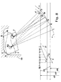
- the spout 11 is in contact with the male end 20 at a point D of attachment, the head 9 being in abutment on the groove 18 at two points A and B.
- This transfer point is determined by the value of an angle a2 between a line joining the pivot R1 and the end of the spout 11 and an upper face of the head 9 opposite the groove 18 of the socket.
- reaction angle x which is that of the reaction force F above with the normal to the generator of the male end 20 at the point of contact D, H or K, must be between certain limits which are a function of the desired locking force, the material of the pipes T1 and T2 and the surface condition of these pipes.
- the insert 7 which bears by its head 9 on the groove 18 of the socket, must be inserted, exerts a reaction force F against the male end 20.
- the force F is directed along a straight line which joins the attachment point of the spout 11 on the male end 20 to the theoretical pivot of rotation R1 or R2.
- the reaction force F makes an angle x with the normal to the generator of the male end 20 at the point of contact D, H or K.
- the reaction angle x is high, the component parallel to the axis X-X of the force F is preponderant compared to its component perpendicular to the axis X-X which theoretically promotes a good locking. Nevertheless, to allow effective attachment of the spout 11 against the external surface of the male end 20, the angle x of the reaction F should not exceed a certain maximum limit beyond which the insert 7 no longer hangs the external surface of the male end 20 and is content to slide against it.
- reaction angle x is small, the horizontal component of the reaction force F becomes negligible compared to its component perpendicular to the axis of the male end, thus, if in this case the beak 11 actually penetrates the surface the male end 20, the force F cannot effectively oppose a push of the pipe T2 by compared to the pipe T1 along the axis XX and therefore cannot oppose a backward movement.
- a curve z is that which joins the different contact points D, H, K, M, L of a spout 11 with the external surface of a male end 20 whose diameter varies according to manufacturing tolerances.
- a curve y represents the variations of the tangent of the angle x, tg x, as a function of the diametral tolerance of the male end, that is to say of the annular clearance j2, j3, j4.
- the insert 7 which already has a fulcrum B against the groove 18 still has a fulcrum A against the rounded surface 14.
- the normal to the contact point A is not parallel to the normal to the inlet collar 19 which displaces the position of the pivot and therefore the angle x of the reaction force. This is the case in FIG. 6.
- a generator of the male end 20 has been graduated according to tg x from 0.4 to 1.
- tg x By projecting each point of the curve y on the generator thus graduated we obtain the value of tg x, from which we can deduce the value of x, for a diameter of the male end 20 passing through the point under consideration of the curve y.
- the inserts 7 reinforce the creep resistance of the lining G and prevent its expulsion towards the outside of the socket 15 when the pipeline contains a fluid under high pressure.
- the inserts 7 improve the anchoring of the heel 2 of the lining G in the nesting groove 18.
- the face 9 of the insert 7 is practically perpendicular to the axis XX and parallel to the face opposite the abutment 17 of the socket.
- the inserts 7 offer low resistance to penetration of the male end and make it easier to insert the axial end of the male end 20 of the pipe T2 into the socket 15 of the pipe T1 (Fig. 4A) and its slight axial withdrawal up to the optimal locking inclination.
- the anchoring zone of the spouts 11 of the inserts 7 on the male end 20 is protected against attack by external fluids by the lip 5 of the lining G (FIG. 4B) which completely closes the entrance to the socket 15.
- the insert 7 behaves, for small annular clearances (j2 ) as having a short length and a large inclination allowing easy attachment of the spout 11, while for large annular clearances (j4) the insert 7 behaves as having a long length and a small inclination which also ensures effective locking.
Landscapes
- Engineering & Computer Science (AREA)
- General Engineering & Computer Science (AREA)
- Mechanical Engineering (AREA)
- Physics & Mathematics (AREA)
- Fluid Mechanics (AREA)
- Joints With Sleeves (AREA)
- Mutual Connection Of Rods And Tubes (AREA)
- Quick-Acting Or Multi-Walled Pipe Joints (AREA)
- Gasket Seals (AREA)
- Joints With Pressure Members (AREA)
- Non-Disconnectible Joints And Screw-Threaded Joints (AREA)
- Refuse Collection And Transfer (AREA)
- Cable Accessories (AREA)
- Braiding, Manufacturing Of Bobbin-Net Or Lace, And Manufacturing Of Nets By Knotting (AREA)
- Connector Housings Or Holding Contact Members (AREA)
- Protection Of Pipes Against Damage, Friction, And Corrosion (AREA)
- Investigating Or Analyzing Materials By The Use Of Ultrasonic Waves (AREA)
- Joints Allowing Movement (AREA)
- Insulators (AREA)
Claims (7)
- Teleskopische Anordnung, die verriegelt und dicht ist, zwischen einem ersten Rohr (T1) mit einer Aufnahme (15) und einem zweiten Rohr (T2) mit einem männlichen Endstück (20), das in die Aufnahme (15) eindringt unter radialer Komprimierung einer Dichtungsgarnitur oder -anordnung aus einem Verbundwerkstoff (G), die zwischen den beiden Rohren (T1, T2) angeordnet ist, wobei die Garnitur (G) aufweist:- einen massiven Körper (1) aus elastischem Material, der radial zwischen einer Kammer (16) des ersten Rohres (T1) und dem männlichen Endstück (20) des zweiten Rohres (T2) komprimiert ist;- einem ringförmigen Ansatz (2) aus elastischem Material, der in Anlage kommt gegen eine ringförmige Aufnahmekerbe (18) am Eingang der Aufnahme;- und einer Mehrzahl von Einsätzen (7) aus Material von großer Härte, die in den Ansatz (2) gemäß den Erzeugenden eines Konus eingebracht sind, der dieselbe Achse (XX) wie die Garnitur (G) aufweist, außerhalb der sie vorspringen, und die jeweils einen Kopf (9), der in dem Ansatz (2) aufgenommen ist, und einen Anhäng- oder Verankerungsschnabel (11) an dem männlichen Endstück (20) des zweiten Rohres (T2) aufweisen,wobei jeder Einsatz (7) in der Lage ist, eine winkelmäßige Verschiebung oder Federung unter Andruck an den Körper (1) der Garnitur (G) beim Vor-Ort-Setzen und dem Verriegeln des männlichen Endstücks (20) vorzunehmen, derart, daß jeder Einsatz (7) sich durch seinen Schnabel (11) an dem männlichen Endstück (20) verstrebt und in Anlage ist mit seinem Kopf (9) an der Kerbe (18) der Aufnahme (15), wobei diese Anlage in zwei Punkten (A, B) für einen ersten Bereich von Durchmessertoleranzen (d2, d3) erfolgt, die schwachen ringförmigen Spielen zwischen dem männlichen Endstück (20) und der Aufnahme (15) entsprechen, und in einem einzigen Punkt (C) der Aufnahme (18) für einen zweiten Durchmesser-Toleranzbereich (d4) erfolgt, der größeren ringförmigen Spielen entspricht.
- Dichtungsanordnung nach Anspruch 1, dadurch gekennzeichnet, daß ein jeder Einsatz (7), der durch eine Lamelle mit rechtwinkligem Querschnitt (8) gebildet wird, ein geknicktes Profil aufweist.
- Dichtungsanordnung nach Anspruch 1 oder 2, dadurch gekennzeichnet, daß ein jeder Einsatz (7) einen breiten Kopf (9) aufweist, der in dem ringförmigen Einsatz (2) der Garnitur (G) aufgenommen ist, einen länglichen Körper (10) aufweist, der den Ansatz bezüglich der Achse (XX) der Garnitur schräg durchquert und einen stumpfen Verschiebe- oder Ablenkwinkel (a, a1) oder Knickwinkel bezüglich des Kopfes (9) bildet, und ein Ende in Form eines Schnabels (11) aufweist, der aus der Garnitur (G) zur Achse (XX) von dieser vorspringt.
- Dichtungsanordnung nach einem der Ansprüche 1 bis 3, dadurch gekennzeichnet, daß das Ende oder der Kopf (9) eines jeden Einsatzes (7), der in dem ringförmigen Ansatz (2) der Garnitur (G) eingesetzt ist, vollständig durch das elastische Material der Garnitur (G) überdeckt ist.
- Dichtungsanordnung nach einem der Ansprüche 1 bis 4, dadurch gekennzeichnet, daß die Garnitur aus einem Verbundwerkstoff (G) in Verlängerung ihres ringförmigen Ansatzes (2) radial und entgegengesetzt zum Ansatz (2) eine schräge ringförmige Lippe (5) aufweist, die zur Achse (XX) der Garnitur wenigstens bis zum minimalen inneren Durchmesser des massiven Körpers (1) der Garnitur (G) konvergiert, wobei die Lippe (5) mit dem massiven Körper (1) eine ringförmige innere Kerbe (4) ausbildet, in deren Innerem ein jeder Einsatz (7) durch seinen Schnabel (11) und einen Bereich seines Körpers (10) vorspringt oder vorsteht.
- Dichtungsanordnung nach Anspruch 5, dadurch gekennzeichnet, daß die schräge ringförmige Lippe (5) und jeder Einsatz (7) schrittweise dieselbe Neigung bezüglich der Achse (XX) der Garnitur aufweisen.
- Dichtungsanordnung nach Anspruch 5, dadurch gekennzeichnet, daß die ringförmige innere Kerbe (4) eine schräge Flanke aufweist, in der Nähe des massiven Körpers (1) und eine schräge Flanke aufweist, die durch die geneigte Lippe (5) gebildet wird, wobei ein ringförmiger Raum (12) zwischen einem jeden Einsatz (7) und der geneigten Flanke in der Nähe des massiven Körpers (1) ausgebildet ist, während ein weiterer ringförmiger Raum (13) zwischen einem jeden Einsatz (7) und der Flanke ausgebildet ist, die durch die schräge Lippe (5) gebildet wird.
Applications Claiming Priority (2)
| Application Number | Priority Date | Filing Date | Title |
|---|---|---|---|
| FR8916524 | 1989-12-11 | ||
| FR8916524A FR2655705B1 (fr) | 1989-12-11 | 1989-12-11 | Garniture d'etancheite composite pour assemblage verrouille de tuyaux a bout male et emboitement. |
Publications (2)
| Publication Number | Publication Date |
|---|---|
| EP0433202A1 EP0433202A1 (de) | 1991-06-19 |
| EP0433202B1 true EP0433202B1 (de) | 1995-03-08 |
Family
ID=9388485
Family Applications (1)
| Application Number | Title | Priority Date | Filing Date |
|---|---|---|---|
| EP90470066A Expired - Lifetime EP0433202B1 (de) | 1989-12-11 | 1990-12-03 | Abdichtanordnung aus einen Verbundwerkstoff für eine verriegelbare Muffenrohrverbindung |
Country Status (23)
| Country | Link |
|---|---|
| EP (1) | EP0433202B1 (de) |
| JP (1) | JPH0743061B2 (de) |
| KR (1) | KR940002042B1 (de) |
| CN (1) | CN1025927C (de) |
| AT (1) | ATE119640T1 (de) |
| AU (1) | AU632190B2 (de) |
| BR (1) | BR9006263A (de) |
| CA (1) | CA2031431C (de) |
| DE (1) | DE69017612T2 (de) |
| DK (1) | DK0433202T3 (de) |
| EG (1) | EG19028A (de) |
| ES (1) | ES2056775T3 (de) |
| FR (1) | FR2655705B1 (de) |
| LT (1) | LT3250B (de) |
| LV (1) | LV10664B (de) |
| MA (1) | MA22011A1 (de) |
| MX (1) | MX173033B (de) |
| OA (1) | OA09277A (de) |
| PT (1) | PT96128B (de) |
| RU (1) | RU2068524C1 (de) |
| TN (1) | TNSN90146A1 (de) |
| TR (1) | TR25643A (de) |
| ZA (1) | ZA909295B (de) |
Families Citing this family (14)
| Publication number | Priority date | Publication date | Assignee | Title |
|---|---|---|---|---|
| FR2679622B1 (fr) * | 1991-07-26 | 1994-09-30 | Pont A Mousson | Garniture d'etancheite composite pour assemblage verrouille de tuyaux, et assemblage verrouille correspondant. |
| LT3294B (en) | 1993-05-12 | 1995-06-26 | Pont A Mousson | Sealing element for fixative assembling of pipes and fixative assembly-joint |
| FR2762054B1 (fr) * | 1997-04-09 | 1999-05-21 | Pont A Mousson | Jonc fendu metallique pour joint verrouille entre elements de canalisation, et joint verrouille correspondant |
| US6688652B2 (en) * | 2001-12-12 | 2004-02-10 | U.S. Pipe And Foundry Company | Locking device and method for securing telescoped pipe |
| JP4566991B2 (ja) | 2003-06-16 | 2010-10-20 | カムウェア、ホールディングス、プロプライエタリ、リミテッド | 回転式の錠および鍵 |
| FR2907877B1 (fr) | 2006-10-31 | 2012-06-22 | Saint Gobain Pont A Mousson | Jonction tubulaire |
| RU2320916C1 (ru) * | 2007-02-21 | 2008-03-27 | Евгений Владимирович Бабаев | Компенсатор для трубопровода, стопор компенсатора и способ монтажа компенсатора |
| JP5473495B2 (ja) * | 2009-09-02 | 2014-04-16 | 株式会社クボタ | 管離脱防止機能付きシール材及び離脱防止管継手 |
| JP5489843B2 (ja) * | 2009-10-07 | 2014-05-14 | 株式会社クボタ | 離脱防止機能付きシール材および離脱防止管継手 |
| JP5534821B2 (ja) * | 2010-01-08 | 2014-07-02 | 株式会社クボタ | 離脱防止機能付きシール材および離脱防止管継手 |
| RU2565481C2 (ru) * | 2014-02-28 | 2015-10-20 | Акционерное общество "Корпорация "Московский институт теплотехники" (АО "Корпорация "МИТ") | Способ сборки газовода с эластичным шарниром |
| JP6594160B2 (ja) * | 2015-10-29 | 2019-10-23 | 株式会社クボタ | シール材および管継手 |
| FR3110661B1 (fr) * | 2020-05-20 | 2023-04-07 | Saint Gobain Pont A Mousson | Insert de verrouillage, garniture d’étanchéité et assemblage correspondants |
| CN116428416B (zh) * | 2023-03-02 | 2025-10-21 | 中交一公局集团有限公司 | 一种大直径热力管道顶管施工装置及其施工工艺 |
Citations (2)
| Publication number | Priority date | Publication date | Assignee | Title |
|---|---|---|---|---|
| FR1490680A (fr) * | 1966-06-22 | 1967-08-04 | Ct De Rech S De Pont A Mousson | Garniture d'étanchéité composite et joint en comportant application |
| EP0406145A1 (de) * | 1989-06-30 | 1991-01-02 | Pont-A-Mousson S.A. | Abdichtanordnung für verriegelte dichte Verbindungen |
Family Cites Families (6)
| Publication number | Priority date | Publication date | Assignee | Title |
|---|---|---|---|---|
| US3272538A (en) * | 1964-11-17 | 1966-09-13 | Union Carbide Corp | Restrained pipe joints |
| GB1550624A (en) * | 1976-06-17 | 1979-08-15 | British Steel Corp | Pipe joints and pipe couplings |
| AU3437478A (en) * | 1977-03-30 | 1979-09-27 | American Cyanamid Co | Prostanoic acids and congeners |
| DE2809307C2 (de) * | 1978-03-03 | 1983-09-15 | Georg 8000 München Seiler | Steckmuffenverbindung von Rohren und Rohrelementen |
| JPS58137186U (ja) * | 1982-03-11 | 1983-09-14 | 株式会社アオイ | 管継手用パツキン |
| FR2621376B1 (fr) * | 1987-10-01 | 1989-12-22 | Pont A Mousson | Garniture d'etancheite pour joints verrouilles telescopiques |
-
1989
- 1989-12-11 FR FR8916524A patent/FR2655705B1/fr not_active Expired - Lifetime
-
1990
- 1990-11-20 ZA ZA909295A patent/ZA909295B/xx unknown
- 1990-11-28 KR KR1019900019364A patent/KR940002042B1/ko not_active Expired - Fee Related
- 1990-12-03 AT AT90470066T patent/ATE119640T1/de not_active IP Right Cessation
- 1990-12-03 DK DK90470066.3T patent/DK0433202T3/da active
- 1990-12-03 ES ES90470066T patent/ES2056775T3/es not_active Expired - Lifetime
- 1990-12-03 DE DE69017612T patent/DE69017612T2/de not_active Expired - Lifetime
- 1990-12-03 EP EP90470066A patent/EP0433202B1/de not_active Expired - Lifetime
- 1990-12-04 CA CA002031431A patent/CA2031431C/fr not_active Expired - Fee Related
- 1990-12-06 TR TR90/1159A patent/TR25643A/xx unknown
- 1990-12-07 MA MA22286A patent/MA22011A1/fr unknown
- 1990-12-07 OA OA59913A patent/OA09277A/xx unknown
- 1990-12-07 RU SU904831779A patent/RU2068524C1/ru active
- 1990-12-07 CN CN90109956A patent/CN1025927C/zh not_active Expired - Lifetime
- 1990-12-07 PT PT96128A patent/PT96128B/pt not_active IP Right Cessation
- 1990-12-09 EG EG72790A patent/EG19028A/xx active
- 1990-12-10 AU AU67895/90A patent/AU632190B2/en not_active Ceased
- 1990-12-10 BR BR909006263A patent/BR9006263A/pt not_active IP Right Cessation
- 1990-12-10 MX MX023670A patent/MX173033B/es unknown
- 1990-12-11 JP JP2415724A patent/JPH0743061B2/ja not_active Expired - Lifetime
- 1990-12-11 TN TNTNSN90146A patent/TNSN90146A1/fr unknown
-
1993
- 1993-03-19 LV LVP-93-195A patent/LV10664B/xx unknown
- 1993-06-04 LT LTIP615A patent/LT3250B/lt not_active IP Right Cessation
Patent Citations (2)
| Publication number | Priority date | Publication date | Assignee | Title |
|---|---|---|---|---|
| FR1490680A (fr) * | 1966-06-22 | 1967-08-04 | Ct De Rech S De Pont A Mousson | Garniture d'étanchéité composite et joint en comportant application |
| EP0406145A1 (de) * | 1989-06-30 | 1991-01-02 | Pont-A-Mousson S.A. | Abdichtanordnung für verriegelte dichte Verbindungen |
Also Published As
| Publication number | Publication date |
|---|---|
| CA2031431A1 (fr) | 1991-06-12 |
| JPH04249690A (ja) | 1992-09-04 |
| LT3250B (en) | 1995-05-25 |
| TR25643A (tr) | 1993-07-01 |
| JPH0743061B2 (ja) | 1995-05-15 |
| DK0433202T3 (da) | 1995-07-17 |
| LV10664B (en) | 1995-10-20 |
| LTIP615A (en) | 1994-12-27 |
| AU632190B2 (en) | 1992-12-17 |
| EG19028A (en) | 1994-11-30 |
| DE69017612D1 (de) | 1995-04-13 |
| CN1025927C (zh) | 1994-09-14 |
| TNSN90146A1 (fr) | 1991-03-05 |
| PT96128A (pt) | 1992-08-31 |
| AU6789590A (en) | 1991-06-13 |
| MX173033B (es) | 1994-01-28 |
| FR2655705A1 (fr) | 1991-06-14 |
| BR9006263A (pt) | 1991-09-24 |
| OA09277A (fr) | 1992-08-31 |
| ZA909295B (en) | 1991-09-25 |
| ES2056775T1 (es) | 1994-10-16 |
| PT96128B (pt) | 1998-07-31 |
| LV10664A (lv) | 1995-04-20 |
| FR2655705B1 (fr) | 1992-05-29 |
| KR940002042B1 (ko) | 1994-03-14 |
| ATE119640T1 (de) | 1995-03-15 |
| KR910012588A (ko) | 1991-08-08 |
| MA22011A1 (fr) | 1991-07-01 |
| RU2068524C1 (ru) | 1996-10-27 |
| ES2056775T3 (es) | 1995-05-16 |
| EP0433202A1 (de) | 1991-06-19 |
| CN1052541A (zh) | 1991-06-26 |
| CA2031431C (fr) | 1995-10-31 |
| DE69017612T2 (de) | 1995-07-06 |
Similar Documents
| Publication | Publication Date | Title |
|---|---|---|
| EP0433202B1 (de) | Abdichtanordnung aus einen Verbundwerkstoff für eine verriegelbare Muffenrohrverbindung | |
| EP0406145B1 (de) | Abdichtanordnung für verriegelte dichte Verbindungen | |
| EP0310534B1 (de) | Dichtungsring für feste Teleskopverbindungen | |
| CA2342720C (fr) | Raccord etanche a geometrie variable | |
| US5219189A (en) | Composite gasket for the locked assembly of spigot and socket pipes | |
| EP1531297B1 (de) | Weiblicher Steckverbinder und Schnellkupplung und Vorrichtung die ein solches Element enthält | |
| EP4048910B1 (de) | Verbindungsvorrichtung mit externem zugang zu einem verankerungsring, entsprechende montage- und entfernungsverfahren | |
| CA1271180A (fr) | Robinet a papillon a caractere universel et procede de fabrication dudit robinet | |
| EP2633218B1 (de) | Rohrverbindung mit einem dichtring, der eine sperreinlage aufweist | |
| LU83496A1 (fr) | Robinet a papillon | |
| EP0399940A1 (de) | Abdichtung und Steckverbindung zur Aufnahme einer solchen Abdichtung und derartig hergestellte Abdichtungsvorrichtung | |
| WO2001094798A1 (fr) | Insert d'implantation d'un raccord de tube dans un logement taraude | |
| FR2737275A1 (fr) | Raccord de tuyaux antiseparation | |
| EP1792110B1 (de) | Stopfbuchsendichtung und entsprechende anordnung | |
| CH619522A5 (de) | ||
| FR2679622A1 (fr) | Garniture d'etancheite composite pour assemblage verrouille de tuyaux, et assemblage verrouille correspondant. | |
| FR3114368A1 (fr) | Système d’étanchéité métallique pour vanne papillon à triple excentration | |
| EP1628061B1 (de) | Ring zur Prüfung der Verpressung eines Rohrpressfittings | |
| EP1860362B1 (de) | Rohrkupplung | |
| EP1605195A1 (de) | Rohrkupplungssystem und dazu gehöriges Montageverfahren | |
| EP4153894A1 (de) | Abgedichtete und verriegelte anordnung | |
| FR2785788A1 (fr) | Implant dentaire pour installer une prothese dentaire ayant une ou plusieurs dents | |
| FR2802234A1 (fr) | Barillet de surete muni d'un moyen anti-crochetage | |
| EP4479620A1 (de) | Schraubverbindung mit vorrichtung zur verhinderung des herausschraubens | |
| EP0524105B1 (de) | Nichtabmontierbares Zwischenstück, insbesondere zum Einstellen der Orientierung von Fahrzeugscheinwerfern |
Legal Events
| Date | Code | Title | Description |
|---|---|---|---|
| PUAI | Public reference made under article 153(3) epc to a published international application that has entered the european phase |
Free format text: ORIGINAL CODE: 0009012 |
|
| AK | Designated contracting states |
Kind code of ref document: A1 Designated state(s): AT BE CH DE DK ES FR GB GR IT LI LU NL SE |
|
| 17P | Request for examination filed |
Effective date: 19911118 |
|
| 17Q | First examination report despatched |
Effective date: 19920909 |
|
| GRAA | (expected) grant |
Free format text: ORIGINAL CODE: 0009210 |
|
| AK | Designated contracting states |
Kind code of ref document: B1 Designated state(s): AT BE CH DE DK ES FR GB GR IT LI LU NL SE |
|
| REF | Corresponds to: |
Ref document number: 119640 Country of ref document: AT Date of ref document: 19950315 Kind code of ref document: T |
|
| ITF | It: translation for a ep patent filed | ||
| GBT | Gb: translation of ep patent filed (gb section 77(6)(a)/1977) |
Effective date: 19950306 |
|
| REF | Corresponds to: |
Ref document number: 69017612 Country of ref document: DE Date of ref document: 19950413 |
|
| REG | Reference to a national code |
Ref country code: ES Ref legal event code: FG2A Ref document number: 2056775 Country of ref document: ES Kind code of ref document: T3 |
|
| REG | Reference to a national code |
Ref country code: DK Ref legal event code: T3 |
|
| REG | Reference to a national code |
Ref country code: GR Ref legal event code: FG4A Free format text: 3016215 |
|
| PLBE | No opposition filed within time limit |
Free format text: ORIGINAL CODE: 0009261 |
|
| STAA | Information on the status of an ep patent application or granted ep patent |
Free format text: STATUS: NO OPPOSITION FILED WITHIN TIME LIMIT |
|
| 26N | No opposition filed | ||
| PGFP | Annual fee paid to national office [announced via postgrant information from national office to epo] |
Ref country code: AT Payment date: 19961121 Year of fee payment: 7 Ref country code: DK Payment date: 19961121 Year of fee payment: 7 |
|
| PGFP | Annual fee paid to national office [announced via postgrant information from national office to epo] |
Ref country code: NL Payment date: 19961125 Year of fee payment: 7 |
|
| PGFP | Annual fee paid to national office [announced via postgrant information from national office to epo] |
Ref country code: LU Payment date: 19961201 Year of fee payment: 7 |
|
| PGFP | Annual fee paid to national office [announced via postgrant information from national office to epo] |
Ref country code: GR Payment date: 19961210 Year of fee payment: 7 |
|
| PGFP | Annual fee paid to national office [announced via postgrant information from national office to epo] |
Ref country code: SE Payment date: 19961218 Year of fee payment: 7 |
|
| PGFP | Annual fee paid to national office [announced via postgrant information from national office to epo] |
Ref country code: CH Payment date: 19961223 Year of fee payment: 7 |
|
| PGFP | Annual fee paid to national office [announced via postgrant information from national office to epo] |
Ref country code: BE Payment date: 19970116 Year of fee payment: 7 |
|
| PG25 | Lapsed in a contracting state [announced via postgrant information from national office to epo] |
Ref country code: LU Free format text: LAPSE BECAUSE OF NON-PAYMENT OF DUE FEES Effective date: 19971203 Ref country code: AT Free format text: LAPSE BECAUSE OF NON-PAYMENT OF DUE FEES Effective date: 19971203 Ref country code: DK Free format text: LAPSE BECAUSE OF NON-PAYMENT OF DUE FEES Effective date: 19971203 |
|
| PG25 | Lapsed in a contracting state [announced via postgrant information from national office to epo] |
Ref country code: SE Free format text: LAPSE BECAUSE OF NON-PAYMENT OF DUE FEES Effective date: 19971204 |
|
| PG25 | Lapsed in a contracting state [announced via postgrant information from national office to epo] |
Ref country code: GR Free format text: LAPSE BECAUSE OF NON-PAYMENT OF DUE FEES Effective date: 19971231 Ref country code: CH Free format text: LAPSE BECAUSE OF NON-PAYMENT OF DUE FEES Effective date: 19971231 Ref country code: BE Free format text: LAPSE BECAUSE OF NON-PAYMENT OF DUE FEES Effective date: 19971231 Ref country code: LI Free format text: LAPSE BECAUSE OF NON-PAYMENT OF DUE FEES Effective date: 19971231 |
|
| BERE | Be: lapsed |
Owner name: S.A. PONT-A-MOUSSON Effective date: 19971231 |
|
| PG25 | Lapsed in a contracting state [announced via postgrant information from national office to epo] |
Ref country code: NL Free format text: LAPSE BECAUSE OF NON-PAYMENT OF DUE FEES Effective date: 19980701 |
|
| REG | Reference to a national code |
Ref country code: CH Ref legal event code: PL |
|
| NLV4 | Nl: lapsed or anulled due to non-payment of the annual fee |
Effective date: 19980701 |
|
| EUG | Se: european patent has lapsed |
Ref document number: 90470066.3 |
|
| REG | Reference to a national code |
Ref country code: DK Ref legal event code: EBP |
|
| REG | Reference to a national code |
Ref country code: GB Ref legal event code: IF02 |
|
| PGFP | Annual fee paid to national office [announced via postgrant information from national office to epo] |
Ref country code: FR Payment date: 20091221 Year of fee payment: 20 Ref country code: GB Payment date: 20091202 Year of fee payment: 20 Ref country code: IT Payment date: 20091218 Year of fee payment: 20 Ref country code: ES Payment date: 20100113 Year of fee payment: 20 |
|
| PGFP | Annual fee paid to national office [announced via postgrant information from national office to epo] |
Ref country code: DE Payment date: 20091126 Year of fee payment: 20 |
|
| REG | Reference to a national code |
Ref country code: GB Ref legal event code: PE20 Expiry date: 20101202 |
|
| PG25 | Lapsed in a contracting state [announced via postgrant information from national office to epo] |
Ref country code: GB Free format text: LAPSE BECAUSE OF EXPIRATION OF PROTECTION Effective date: 20101202 |
|
| PG25 | Lapsed in a contracting state [announced via postgrant information from national office to epo] |
Ref country code: DE Free format text: LAPSE BECAUSE OF EXPIRATION OF PROTECTION Effective date: 20101203 |
|
| REG | Reference to a national code |
Ref country code: ES Ref legal event code: FD2A Effective date: 20130724 |
|
| PG25 | Lapsed in a contracting state [announced via postgrant information from national office to epo] |
Ref country code: ES Free format text: LAPSE BECAUSE OF EXPIRATION OF PROTECTION Effective date: 20101204 |