EP0433226A2 - Dispositif de déchargement pour un récipient métallurgique - Google Patents
Dispositif de déchargement pour un récipient métallurgique Download PDFInfo
- Publication number
- EP0433226A2 EP0433226A2 EP90810935A EP90810935A EP0433226A2 EP 0433226 A2 EP0433226 A2 EP 0433226A2 EP 90810935 A EP90810935 A EP 90810935A EP 90810935 A EP90810935 A EP 90810935A EP 0433226 A2 EP0433226 A2 EP 0433226A2
- Authority
- EP
- European Patent Office
- Prior art keywords
- yoke
- rod
- coupling rod
- plug
- outlet device
- Prior art date
- Legal status (The legal status is an assumption and is not a legal conclusion. Google has not performed a legal analysis and makes no representation as to the accuracy of the status listed.)
- Withdrawn
Links
Images


Classifications
-
- B—PERFORMING OPERATIONS; TRANSPORTING
- B22—CASTING; POWDER METALLURGY
- B22D—CASTING OF METALS; CASTING OF OTHER SUBSTANCES BY THE SAME PROCESSES OR DEVICES
- B22D41/00—Casting melt-holding vessels, e.g. ladles, tundishes, cups or the like
- B22D41/14—Closures
- B22D41/16—Closures stopper-rod type, i.e. a stopper-rod being positioned downwardly through the vessel and the metal therein, for selective registry with the pouring opening
- B22D41/20—Stopper-rod operating equipment
Definitions
- the invention relates to an outlet device with a movable sealing plug for controlling the flow of molten metals from a metallurgical vessel, with a regulating piston engaging in a bore at the lower end of a plug rod and with a yoke connected to the upper end region of the plug rod.
- Such an outlet device is known from EP 879074123, in which a stopper in the form of a regulating piston engages appropriately in a hole in a perforated brick.
- a stopper in the form of a regulating piston engages appropriately in a hole in a perforated brick.
- the stopper rod At the upper end of the stopper rod it is connected to a yoke, which is provided outside the metallurgical vessel with drive elements for the height adjustment and, if necessary, for a rotary movement.
- the yoke In order to be able to insert the stopper rod with the control piston vertically into the pouring hole from above, the yoke must first be swung away. Then the yoke must be swung back and aligned with the stopper rod.
- Control piston is particularly sensitive to breakage when subjected to bending stress. The control piston can easily break off when the heavy yoke is moved or the upper end of the piston rod is not precisely aligned.
- the object to be achieved with the invention is to connect the yoke to the stopper rod even when there are deviations in position and / or angle, while avoiding bending stresses, and to ensure that the control piston fits snugly in the hole in the perforated brick.
- the plug rod should also be able to be installed without moving the yoke.
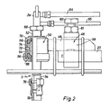
- a perforated brick 3 ' In the bottom of a metallurgical vessel 1 there is a perforated brick 3 'with a through-opening for receiving a control piston 3. At the perforated brick 3' an outlet pipe 3 ⁇ shoots below.
- the vessel 1 and the perforated brick 3 ' are made of refractory material.
- the bath level of the molten metal can reach the height H.
- the control piston 3 is provided with at least one approximately radial flow opening 14 which opens into a central bore which is open at the bottom.
- the flow of the melt can thus be regulated or interrupted by adjusting the height of this control piston 3.
- a seal exists when the regulating piston 13 projects into the bore 7 with its part closed on the circumference. However, there can also be two cumulative seals according to EP 879074123.
- the stopper head 6 contains a widened part, to which a stopper jacket 10 adjoins at the top, which ends above the bath height H. Inside this stuffing jacket 10 there is a central bore into which a plug rod 5 engages with radial play.
- the stopper rod 5 can be mounted at the bottom in a joint, preferably a ball joint 11 or universal joint, or can be rigidly installed.
- a bearing 50 In the upper end region of the plug rod 5 there is a bearing 50, from which a coupling rod 48 projects radially and horizontally. This coupling rod 48 is detachably connected to a yoke 23 by a clamping device 46.
- the yoke 23 is supported outside of the metallurgical vessel 1 by height-adjustable elements and serves to raise or lower the stopper rod 5 and thus the control piston 3.
- the vertical movement of the yoke 23 is carried out by means of a hydraulic cylinder 8, the yoke 23 in a vertical cylinder column 9 is led.
- the cylinder column 9 and the hydraulic cylinder 8 are attached to a frame 62, which in turn is rigidly connected to the metallurgical vessel 1.
- For the supply and removal of cooling air Lines 64, 65 are present, which are connected to longitudinal bores of the plug rod 5.
- the bearing 50 is designed as a spherical joint bearing which can be moved on all sides and which contains a spherical inner insert 54 which is screwed onto a threaded spindle 52.
- the threaded spindle 52 is hollow and is penetrated by the plug rod 5.
- the height of the spherical insert 54 can be adjusted by rotating the threaded spindle 52 relative to the plug rod 5 with the aid of a hexagon set 66.
- Bearing rings 56 which are supported in the housing 68 and its cover 70, bear against the spherical insert 54 on the outside at the top and bottom.
- a pin 72 fastened in the housing 68 projects with play into a vertical groove 74 of the spherical insert 54.
- the plug rod 5 is divided in its length. The two sections 5a, 5b are held together by a union nut 76.
- the yoke 23 and the coupling rod 48 lie against one another with two flat surfaces and are rigidly clamped by the clamping device 46 by tightening the screw 60 and the lock nut 61 by means of a bracket-like bracket 58.
- the bearing surface of the yoke 23 is considerably wider than the bearing surface of the coupling rod 48 which bears against it, so that the coupling rod 48 can assume different angular positions and longitudinal positions relative to the yoke 23, as can be seen from FIGS. 3 and 4.
- the spout or the perforated brick 3 ' is not precisely walled in the bottom of the metallurgical vessel, there may be differences in position of the plug rod 5, which are due to the leverage strongly on the relatively long plug rod 5 can impact at the top.
- these angular and positional differences z, x - compared to a theoretical target position - can be compensated for by the releasable clamp connection.
- the yoke 23 is always at a certain radial distance from the spherical bearing 50, so that the jacket 10 together with the plug rod 5 from above by a crane or the like.
- FIGS. 3 and 4 show different angular positions () between coupling rod 48 and yoke 23.
- the control tube 3 together with the plug rod 5 can be inserted past the yoke 23 vertically from above into the hole in the perforated brick 3. Moving and precisely aligning the heavy yoke 23 is no longer necessary.
- the coupling rod 48 could also be brought to bear against the underside of the yoke 23. Furthermore, it is possible, instead of the clamping screw 60, to effect the clamping action in some other way, for example by means of a hydraulic pressure unit.
Landscapes
- Engineering & Computer Science (AREA)
- Mechanical Engineering (AREA)
- Casting Support Devices, Ladles, And Melt Control Thereby (AREA)
- Furnace Charging Or Discharging (AREA)
- Continuous Casting (AREA)
Applications Claiming Priority (2)
| Application Number | Priority Date | Filing Date | Title |
|---|---|---|---|
| CH450389 | 1989-12-14 | ||
| CH4503/89 | 1989-12-14 |
Publications (2)
| Publication Number | Publication Date |
|---|---|
| EP0433226A2 true EP0433226A2 (fr) | 1991-06-19 |
| EP0433226A3 EP0433226A3 (en) | 1993-12-29 |
Family
ID=4277323
Family Applications (1)
| Application Number | Title | Priority Date | Filing Date |
|---|---|---|---|
| EP19900810935 Withdrawn EP0433226A3 (en) | 1989-12-14 | 1990-11-30 | Discharging device for a metallurgical vessel |
Country Status (3)
| Country | Link |
|---|---|
| EP (1) | EP0433226A3 (fr) |
| JP (1) | JPH049266A (fr) |
| AU (1) | AU642451B2 (fr) |
Cited By (2)
| Publication number | Priority date | Publication date | Assignee | Title |
|---|---|---|---|---|
| EP0567227A1 (fr) * | 1992-03-24 | 1993-10-27 | Crane Limited | Moyen obtinateur |
| DE4232006A1 (de) * | 1992-09-24 | 1994-03-31 | Leybold Ag | Vorrichtung zum Öffnen und Schließen einer Bodenabgußöffnung in einem Vakuum-Induktionsschmelz- und -gießofen |
Families Citing this family (2)
| Publication number | Priority date | Publication date | Assignee | Title |
|---|---|---|---|---|
| KR100654891B1 (ko) * | 2005-07-05 | 2006-12-06 | 주식회사 포스코 | 용강 유출 차단장치 및 이를 이용한 용강 유출 차단방법 |
| JP2010236026A (ja) * | 2009-03-31 | 2010-10-21 | Mitsubishi Materials Corp | アトマイズ装置 |
Family Cites Families (7)
| Publication number | Priority date | Publication date | Assignee | Title |
|---|---|---|---|---|
| DE166049C (fr) * | ||||
| US3214804A (en) * | 1963-03-18 | 1965-11-02 | Allegheny Ludlum Steel | Ladles |
| US3386633A (en) * | 1966-04-20 | 1968-06-04 | Nadrich John | Closure for a bottom pour metallurgical ladle |
| US3643680A (en) * | 1970-09-14 | 1972-02-22 | Kelsey Hayes Co | Bottom pour stopper |
| US3952922A (en) * | 1975-06-27 | 1976-04-27 | General Motors Corporation | Precessing bottom pour stopper having swinging movement |
| EP0084416B1 (fr) * | 1982-01-18 | 1986-09-03 | Stephen David Mills | Support de quenouille pour poches de coulée |
| AU591889B2 (en) * | 1985-03-26 | 1989-12-21 | British Steel Plc | Improvements in or relating to outlet valves for metal containing vessels |
-
1990
- 1990-11-30 EP EP19900810935 patent/EP0433226A3/de not_active Withdrawn
- 1990-12-06 AU AU67839/90A patent/AU642451B2/en not_active Ceased
- 1990-12-14 JP JP41062990A patent/JPH049266A/ja active Pending
Cited By (2)
| Publication number | Priority date | Publication date | Assignee | Title |
|---|---|---|---|---|
| EP0567227A1 (fr) * | 1992-03-24 | 1993-10-27 | Crane Limited | Moyen obtinateur |
| DE4232006A1 (de) * | 1992-09-24 | 1994-03-31 | Leybold Ag | Vorrichtung zum Öffnen und Schließen einer Bodenabgußöffnung in einem Vakuum-Induktionsschmelz- und -gießofen |
Also Published As
| Publication number | Publication date |
|---|---|
| EP0433226A3 (en) | 1993-12-29 |
| AU6783990A (en) | 1991-06-20 |
| AU642451B2 (en) | 1993-10-21 |
| JPH049266A (ja) | 1992-01-14 |
Similar Documents
| Publication | Publication Date | Title |
|---|---|---|
| DE1227926C2 (de) | Kernloser, insbesondere mit Netzfrequenz betriebener Induktions-Schmelz- und/oder Warmhalteofen fuer Vakuumbetrieb | |
| DE2125175A1 (de) | Schieberverschluß an Behältern für flüssige Schmelzen | |
| EP0302215B1 (fr) | Vanne rotative pour conteneur métallurgique ainsi que rotor et stator pour une telle vanne | |
| EP0433226A2 (fr) | Dispositif de déchargement pour un récipient métallurgique | |
| DE2738587C2 (de) | Verstellvorrichtung für eine Abschirmvorrichtung zum Gießstrahlschutz | |
| DE2043588A1 (de) | Drehschieberverschluß an Behältern für flüssige Schmelze | |
| DE3319009C2 (de) | Verschluß für einen geschmolzenes Material enthaltenden Behälter | |
| DE1125121B (de) | Vorrichtung fuer Giesspfannen zum Giessen von Metallen | |
| WO2018202618A1 (fr) | Porte-chalumeau | |
| DE4232006A1 (de) | Vorrichtung zum Öffnen und Schließen einer Bodenabgußöffnung in einem Vakuum-Induktionsschmelz- und -gießofen | |
| DE4315709C2 (de) | Schiebeausguß für ein Stahlschmelze-Aufnahmegefäß | |
| EP0077319B1 (fr) | Four électrique | |
| DE2417489C3 (de) | Ausguß für metallurgische Gefäße | |
| EP0216187B1 (fr) | Conteneur de four métallurgique, en particulier d'un four à arc | |
| EP0480202B1 (fr) | Dispositif de fermeture et/ou de régulation pour la busette de récipients contenant du métal | |
| DE4032787A1 (de) | Vorrichtung zum anschliessen eines giessrohres an den ausguss eines metallschmelze enthaltenden gefaesses | |
| DE3900961C1 (fr) | ||
| EP0378818A1 (fr) | Obturateur rotatif pour récipient pourvu d'un trou de coulée de fond | |
| DE3044087A1 (de) | Stichlochbohrmaschine | |
| EP1687109B1 (fr) | Dispositif pour actionner un systeme de fermeture coulissant mis en place contre un recipient contenant du metal en fusion | |
| DE4103269C2 (de) | Abgußvorrichtung für flüssige Chargen aus einem kippbaren Bahälter | |
| DE1783174C3 (de) | Verfahren und Hilfsvorrichtung für den Einbau und die Justierung der feuerfesten Einzelteile von regelbaren Bodenverschlüssen für Stahlgießpfannen | |
| DE68920334T3 (de) | Vorrichtung zum regeln der fliessgeschwindigkeit von geschmolzenem metall. | |
| EP0073537A1 (fr) | Support du conduit d'évacuation des gaz d'un four à arc | |
| WO1998016337A1 (fr) | Mecanisme d'entrainement destine a un organe de fermeture et/ou de regulation pour la rigole de coulee d'un reservoir contenant une masse de metal en fusion |
Legal Events
| Date | Code | Title | Description |
|---|---|---|---|
| PUAI | Public reference made under article 153(3) epc to a published international application that has entered the european phase |
Free format text: ORIGINAL CODE: 0009012 |
|
| AK | Designated contracting states |
Kind code of ref document: A2 Designated state(s): AT BE CH DE ES FR GB IT LI LU SE |
|
| PUAL | Search report despatched |
Free format text: ORIGINAL CODE: 0009013 |
|
| AK | Designated contracting states |
Kind code of ref document: A3 Designated state(s): AT BE CH DE ES FR GB IT LI LU SE |
|
| STAA | Information on the status of an ep patent application or granted ep patent |
Free format text: STATUS: THE APPLICATION IS DEEMED TO BE WITHDRAWN |
|
| 18D | Application deemed to be withdrawn |
Effective date: 19940630 |