EP0433400B1 - Systeme electronique de gestion energetique alimente en energie solaire - Google Patents
Systeme electronique de gestion energetique alimente en energie solaire Download PDFInfo
- Publication number
- EP0433400B1 EP0433400B1 EP90901115A EP90901115A EP0433400B1 EP 0433400 B1 EP0433400 B1 EP 0433400B1 EP 90901115 A EP90901115 A EP 90901115A EP 90901115 A EP90901115 A EP 90901115A EP 0433400 B1 EP0433400 B1 EP 0433400B1
- Authority
- EP
- European Patent Office
- Prior art keywords
- power
- irrigation
- controller
- energy
- power source
- Prior art date
- Legal status (The legal status is an assumption and is not a legal conclusion. Google has not performed a legal analysis and makes no representation as to the accuracy of the status listed.)
- Expired - Lifetime
Links
Images







Classifications
-
- H—ELECTRICITY
- H02—GENERATION; CONVERSION OR DISTRIBUTION OF ELECTRIC POWER
- H02J—ELECTRIC POWER NETWORKS; CIRCUIT ARRANGEMENTS OR SYSTEMS FOR SUPPLYING OR DISTRIBUTING ELECTRIC POWER; SYSTEMS FOR STORING ELECTRIC ENERGY
- H02J7/00—Circuit arrangements for charging or discharging batteries or for supplying loads from batteries
- H02J7/34—Parallel operation in networks using both storage and other DC sources, e.g. providing buffering
- H02J7/35—Parallel operation in networks using both storage and other DC sources, e.g. providing buffering with light sensitive cells
-
- A—HUMAN NECESSITIES
- A01—AGRICULTURE; FORESTRY; ANIMAL HUSBANDRY; HUNTING; TRAPPING; FISHING
- A01G—HORTICULTURE; CULTIVATION OF VEGETABLES, FLOWERS, RICE, FRUIT, VINES, HOPS OR SEAWEED; FORESTRY; WATERING
- A01G25/00—Watering gardens, fields, sports grounds or the like
- A01G25/16—Control of watering
-
- G—PHYSICS
- G06—COMPUTING OR CALCULATING; COUNTING
- G06F—ELECTRIC DIGITAL DATA PROCESSING
- G06F3/00—Input arrangements for transferring data to be processed into a form capable of being handled by the computer; Output arrangements for transferring data from processing unit to output unit, e.g. interface arrangements
- G06F3/01—Input arrangements or combined input and output arrangements for interaction between user and computer
- G06F3/048—Interaction techniques based on graphical user interfaces [GUI]
- G06F3/0487—Interaction techniques based on graphical user interfaces [GUI] using specific features provided by the input device, e.g. functions controlled by the rotation of a mouse with dual sensing arrangements, or of the nature of the input device, e.g. tap gestures based on pressure sensed by a digitiser
- G06F3/0489—Interaction techniques based on graphical user interfaces [GUI] using specific features provided by the input device, e.g. functions controlled by the rotation of a mouse with dual sensing arrangements, or of the nature of the input device, e.g. tap gestures based on pressure sensed by a digitiser using dedicated keyboard keys or combinations thereof
-
- Y—GENERAL TAGGING OF NEW TECHNOLOGICAL DEVELOPMENTS; GENERAL TAGGING OF CROSS-SECTIONAL TECHNOLOGIES SPANNING OVER SEVERAL SECTIONS OF THE IPC; TECHNICAL SUBJECTS COVERED BY FORMER USPC CROSS-REFERENCE ART COLLECTIONS [XRACs] AND DIGESTS
- Y02—TECHNOLOGIES OR APPLICATIONS FOR MITIGATION OR ADAPTATION AGAINST CLIMATE CHANGE
- Y02P—CLIMATE CHANGE MITIGATION TECHNOLOGIES IN THE PRODUCTION OR PROCESSING OF GOODS
- Y02P60/00—Technologies relating to agriculture, livestock or agroalimentary industries
- Y02P60/12—Technologies relating to agriculture, livestock or agroalimentary industries using renewable energies, e.g. solar water pumping
Definitions
- the present invention concerns self-energized irrigation control systems and controllers, and particularly irrigation control systems that derive their operational energy at times from light.
- irrigation controllers were self-energized, and did not require a.c. power, then they could be located closer to the valves, and the length of low voltage wiring from the dispersed self-energized controllers to the valves would be much reduced.
- the contractor's wiring costs for the same installation might then be reduced by up to 85%. There is thus a very great cost savings if a.c. wiring could be eliminated in an irrigation control system. If the costs of controllers and valves remained the same (which is by no means certain) then the overall irrigation system installation cost might decrease by up to 54% (i.e., 63% x 85%).
- a typical solenoid-actuated diaphragm valve of which many tens or hundreds are typically used in an irrigation system, draws about .25 ampere continuous current at 24 v.a.c., or continuously dissipates about 6 watts.
- These solenoid-actuated valves are driven by electronic or electromechanical controllers. Because of the heavy power consumption of the solenoids, these systems are typically connected to a.c. power.
- Latching solenoid-actuated diaphragm valves are available that draw current for a lesser time duration only upon opening and closing (latching and unlatching). Although these latching solenoid valves are generally more expensive, more complex, and more failure prone, they do reduce total system energy requirements. However, an irrigation system using latching solenoid valves still typically requires about 6 watts instantaneous power upon each occasion of a valve actuation.
- the power requirements of an efficient, modern, irrigation control system having a controller and eight typical solenoid valves will thus be recognized to be on the order of 66 watts when driving a valve.
- CMOS complementary Metal Oxide Semiconductor
- MSI Medium Scale Integrated
- LSI Large Scale Integrated
- Such a low power irrigation controller might be built to consume less than .01 watts, or 240 milliwatt hours per day. On this power the controller would do sufficient calculation, and would execute an irrigation schedule, that would be sufficient to cycle one or more irrigation valves about 128 total times for all valves. Each of these valve cycles would consume about 480 milliwatt seconds or .13 milliwatt hours. The total 128 valve cycles would thus consume about 17 milliwatt hours.
- the energy budget for a very, very low power custom irrigation system would thus be on the order of 257 milliwatt hours per day, plus losses. This is on the order of 5000 times less than the 1440 watt hours that a conventional controller might use daily. It will be discussed in the following sections how difficult it is to meet even this modest energy budget.
- a battery has a low internal resistance, and can typically easily supply the 200 ma of current needed for a short time (about 100 msec) by a latching solenoid valve.
- the total energy consumption of energy-efficient irrigation systems may also be satisfied by batteries.
- At least one previous battery-powered irrigation controller exists in the market circa 1988. It uses four standard 6 volt lantern batteries.
- Dry cell batteries have proven unreliable to meet the power demands of irrigation control.
- the battery is in an outdoor enclosure, and is subject to all prevailing climatic extremes of heat, cold, and humidity.
- the precise longevity of the battery which is in part based on its intermittent power drain for controlling the switching of irrigation valves, is difficult to calculate.
- the batteries typically require replacement bimonthly or sooner. Even when often replaced (at considerable cost) the batteries are prone to deteriorate without warning to a condition inadequate to power the irrigation system. Because great damage to vegetation due to underwatering can quickly accrue, especially during hot weather, the failure of an irrigation system due to battery power failure is a highly detrimental occurrence.
- wet cell batteries although exhibiting a greater longevity than dry cell batteries, have a relatively short lifetime of months or years. They are expensive and cumbersome to replace. They may be unsafe in some applications where electrolyte leakage could be hazardous to plant or animal life.
- Capacitors are a known means of storing electrical charge, or power. Relatively new high performance electrolytic capacitors based on carbon paste electrodes store large electrical charges. One such capacitor is the subject of U.S. Patent No. 3,536,963.
- super capacitors have high equivalent series resistance (ESR), and are accordingly limited in the amount of power that each can deliver per unit time. Although considerate total power can be extracted from many tens, or hundreds of these super capacitors in a parallel array, just a few super capacitors are typically unable to provide adequate current flow so as to actuate a low-power latching solenoid valve.
- ESR equivalent series resistance
- An energy source for a self-energized irrigation system would normally be designed to supply all normal, quiescent, energy requirements of the system. If the self-contained energy source were to be solar powered, then the energy collection and storage capacity should be sufficient to maintain the system in operation during periods of night, successive cloudy days, etc.
- a self-energized irrigation system must countenance the asynchronous arrival, night or day, of a user-maintainer of the system.
- the user-maintainer may proceed to communicate with the irrigation controller, cycle the irrigation valves, and/or initiate an irrigation schedule that may call for numerous immediate valve cyclings.
- Each of these activities is individually difficult to budget and to satisfy with necessary energies.
- a self-contained energy source within an irrigation controller or system must power the communication of the system then it must store much more energy than would be needed for quiescent operation.
- Yet asynchronously-occurring communication demands on the irrigation system by a user-maintainer are completely routine, and are to be expected. These demands place a great, essentially unquantifiable and uncontrolled, demand on the energy source of any self-energized irrigation system. Even when the system energy source is of adequate capacity to meet these demands temporarily, as is normally the case with batteries, it is very common that a user-maintainer's communication with the system will seriously deplete or exhaust the power storage of the system.
- a rechargeable self-contained energy source such as a battery recharged by solar power, may have exhausted its day's energy budget in performance of irrigation control and be awaiting recharge prior to again controlling the same diurnal cycle of irrigation.
- a user-maintainer may set up a new irrigation schedule, while the energy source is depleted, that calls for an immediate energy drain. This energy drain will occur before the source may be, in due course, recharged. It is thus not sufficient that a self-energized irrigation system should avoid unbudgeted energy losses during communication with, or exercise by, a maintainer-user. Rather, the system's energy source must be, for certain scenarios, left with more energy storage after communication than before.
- no self-powered irrigation system is likely to store sufficient energy so as to permit that an unscheduled energy drain of significant magnitude may occur asynchronously with normal system power drains for the conduct of irrigation.
- the present invention contemplates powering an electrical system from multiple power sources, the choice of power source being in accordance with the nature of the work that is, at different times, performed by the system.
- the system is typically an irrigation system that includes an electronic irrigation controller and electrically-actuated valves.
- the controller at different times, (i) performs irrigation control and (ii) communicates, either directly or indirectly through an interface, with a user/programmer of the irrigation system.
- a light-energized first power source supplies all necessary energy to the irrigation system for its function of irrigation.
- This first power source includes photovoltaic devices for converting light to electricity and high performance capacitors for energy storage during periods of darkness.
- a second power source supplies all necessary energy to the irrigation controller of the irrigation system for its communication function.
- This second power source is portable, and is typically a battery. The battery is transported to the irrigation controller and electrically connected thereto in order to initiate, as well as to power, communication of the controller with a user/programmer. This communication may either be direct though a man/machine interface provided by local control panel, or indirect through a communications link provided by an I/O port of custom design.
- the irrigation control that is powered by the light-energized first power source typically requires less power per unit time than the user communication that is powered by the portable second power source. This is the case whether or not the user communication transpires through a man/machine interface by the display of messages and the receipt of switch acuations, or through an I/O channel by the communication of electrical signals.
- the communication typically takes more power and energy not only because of its requirement to drive a display or transmit an electrical signal, which each require energy, but because the control of irrigation will, in accordance with a further aspect of the present invention to be later explained, require so little power and energy.
- the present invention contemplates supplying power from the portable second power source to keep the controller "up” and communicating, when most power is needed, and from a light-energized first power source elsetimes.
- the dilemma of needing to asynchronously communicate day or night with a power-budgeted electrical system, such as an irrigation controller, having limited power reserves is thereby solved. This is because the initiation of communication inherently brings with it the necessary power to conduct the communication.
- the energy storage capacitors of the first power source are charged by the battery of the second power source. This means that each communication undertaken with the irrigation controller leaves the first power source fully charged and capable of powering subsequent irrigation control, even irrigation control that must commence at night or after the system had previously been subject to a period of disuse and discharge.
- the second power source not only satisfies the power requirements for communication but always leaves the irrigation system ready to function to the utmost of its first power source storage capacity.
- the present invention still further contemplates a new type of power source that stores energy that is derived from light as electrical charge on a capacitor, and particularly on a high performance capacitor.
- a photovoltaic power source produces voltage in the presence of light energy.
- a capacitor is diode-connected across the photovoltaic power source. The capacitor accumulates electrical charge from the voltage developed by the photovoltaic power source.
- a voltage sensor connected across the capacitor produces a control signal when the charge upon the capacitor exceeds a predetermined reference level.
- a delay circuit receives the control signal and delays it in time in order to produce a delayed control signal.
- a controllable electrical shunt circuit connected across the photovoltaic power source short circuits the voltage produced by the photovoltaic power source selectively during receipt of the delayed control signal.
- the first power source's capacitors are typically of an electric double layer type that store electrical charge at an interface by an electric field between two available phases.
- One phase is typically activated carbon, and the other phase is an ionically conducting electrolyte, typically sulfuric acid solution.
- Such capacitor type is commonly called a high performance, or "super”, capacitor, and is capable of storing large energies.
- super capacitors each of 1 farads capacitance are used within the preferred embodiment of the first power source.
- the photovoltaic power source typically produce 35 ma at 10 v.d.c., or 350 milliwatts, at one sun light level from an extremely modest size collector area of 18 square inches. This power production is significantly derated for dim light due to overcast weather or siting, northern latitudes, transmission losses through a transparent cover that may become dirty, and during hours of darkness. Under worse case light levels and siting conditions the photovoltaic power source produces 7.6 mWH of energy daily.
- the energy storage and production capacities of the preferred embodiment of the first power source present an extremely challenging energy and power budget for even the quiescent, non-communication, control of an irrigation system.
- the irrigation controller is fully “awake' and operating to control irrigation stations only for very short periods of time, on the order of fractions of a second, at typically long time separations, on the order of minutes or hours.
- the controller is typically awake for 10 milliseconds every second.
- An elapsed time clock within the controller is constantly updated from a constant frequency source.
- the rest of the controller logic consisting primarily of a microprocessor, is completely “dead", or static and.inoperative. In this state the logic consumes virtually no power.
- An elapsed time clock is implemented in CMOS circuitry. It consumes extremely little power, typically much less than a digital watch that must also drive a display.
- the microprocessor and associated logic circuitry are preferably also implemented in CMOS logic, preferably as two Application Specific Integrated Circuits (ASICs).
- ASICs Application Specific Integrated Circuits
- the entire controller consumes, on a 24 hour basis (of which day the controller is awake only an infinitesimal amount of time) no more energy than 6.4 milliwatt hours.
- the controller will calculate and execute an irrigation schedule that may control the cycling of one or more ultra-low power irrigation valves up to a total 128 cycles among all valves.
- the irrigation controller In order to perform communication the irrigation controller must be up and running, or "awake". This means, in the case of a microprocessor-based irrigation controller, that the microprocessor must operate at an acceptable duty cycle and clock rate commensurate with its computational responsibilities to manage communication. The irrigation scheduling and control task is computationally trivial by comparison.
- the irrigation system that uses the present invention will preferably be implemented with ultra-low power valve actuators.
- Such actuators if used would consume on the order of 9.4 microwatt hours per cycle or 1.2 milliwatt hours daily in performing on the order of 128 actuation cycles.
- Such actuators if used would make the energy consumption of the entire irrigation system to be on the order of 7.6 milliwatt hours per day. This is the minimum power output from the photovoltaic module.
- the self-energized irrigation controller can store enough energy to control 128 irrigation valve cycles without intervening recharge.
- it can collect sufficient light energy for sustained operation by collection of the incident light falling upon approximately 18 square inches even in northern latitudes (e.g., Canada) on cloudy days. The light-energized first power source will even power the irrigation controller by bright moonlight.
- the light energized irrigation controller in accordance with the present invention thus is vastly different from prior irrigation controllers and systems requiring a.c. power, large batteries, and/or large solar collectors.
- This light-energized quiescent operation is enabled in part because the operation of the controller for communication, drawing more power per unit time, is energized by the portable second, battery, power source.
- This light-energized quiescent operation is further enabled in part because the controllers active, "on", periods transpire only when and for such duration as is absolutely necessary, with almost all of the power-consuming portion of the controller remaining in a totally unpowered state for almost all of the time.
- the present invention is embodied in an 8-station light-energized irrigation controller.
- the irrigation controller is spoken of as being “light-energized” and (along with the irrigation valves that it controls) to embody “Light-Energized Irrigation Technology” (LEIT).
- LEIT Light-Energized Irrigation Technology
- This description is in lieu of describing, for example, the controller to be “solar powered” because it employs an extremely small area light (solar) collector. Resultant to the small energy collected, the controller uses extremely little energy for all irrigation functions, including control of up to eight (8) valves.
- the acronym LEIT when applied to irrigation controllers is a trademark of Solatrol, Inc. i.e., LEITTM Irrigation Controllers.
- Light energy required is 0.4 milliwatts/sq cm incident light for a minimum of 7 hrs/day. This is equivalent to one tenth of the amount of light at 55° northern latitude (e.g., in Canada) on a cloudy winter's day.
- the power for the controller's display (when actuated) is derived from a POWERKEYTM (trademark of Solatrol, Inc.) power source.
- the POWERKEYTM power source packages a 9-volt alkaline battery that is used to energize the Liquid Crystal Display (LCD) of the controller during installation and programming.
- LCD Liquid Crystal Display
- the signal output of the controller to its controlled valves is 3.5 volts DC, 0.04 amps. No circuit breaker and no transformer are required.
- Up to 8 valves may be connected to each controller. Up to 8 electronic soil moisture sensors or optionally, other electronic sensing devices, may also be connected to each controller.
- a user-defined emergency backup program and critical system parameters are stored in non-volative memory in case of memory loss from prolonged light interruption; no batteries are needed.
- LEIT Irrigation controller in accordance with the present invention interfaces to certain optional accessories and equipments.
- a POWERKEYTM (trademark of Solatrol, Inc.) power source is a combination keyring and keyfob-cased battery for powering the display during programming and/or interactive operation.
- An optional MultiprogrammerTM unit plugs into the digital interface of the controller for uploading and downloading the watering programs for up to 64 controllers.
- An optional WIRESCOPETM (trademark of Solatrol, Inc.) unit is a hand-held diagnostic unit that checks for proper controller and valve operation from the valve station end of each station wire, and can optionally give an identifying readout of valve and sensor numbers by station and controller.
- Up to 8 optional soil moisture sensor units can connect to the controller to give precise irrigation system control based on readings of available soil moisture tension, or optionally, percentage soil saturation.
- An optional remote test command assembly is a replacement controller face-plate that receives signals from a hand-held transceiver in order to allow wireless remote "manual" operation of valves and sensors from the valve or sensor locations.
- An optional radio-link central module mounts permanently below the controller and acts as a transceiver for wireless communication between the controller and a radio-link central system.
- the POWERKEYTM power source is manually plugged to the controller in order to provide power to the controller for first use precharging, and during each occurrence of the programming/parameterization of the controller's operation and/or the reviewing of data in the controller's memory. In the latter two cases, the POWERKEYTM power source also provides built-in illumination of the controller's display and control switches.
- the power source during operation of the controller to control irrigation may be the POWERKEYTM power source if it is still pluggably attached (an abnormal condition), but is normally light (even extremely dim light, such as moonlight) that falls upon the controller.
- the preferred embodiment of an irrigation controller in accordance with the present invention is light-energized with a built-in incident light collector. It exhibits sufficient energy storage to drive a custom CMOS ultra-low-power microcomputer with 32K RAM memory and to cycle up to eight (8) ultra-low-power irrigation valves up to sixteen (16) times per twenty-four (24) hour period. This provides complete independence from any need for AC power, saving on energy and installation costs and permitting the controller to be located closer to the valves.
- the preferred embodiment of an irrigation controller in accordance with the present invention uses L ight E nergized I rrigation T echnology (LEITTM). It can operate with the amount of incident light available in northern latitudes on a worst-case cloudy winter's day without needing any of the batteries, external solar panels, or the A.C. power connections required for traditional controllers. It is also extremely flexible and versatile in its operation.
- Controller 1 is typically attached to post 2.
- An array of photovoltaic devices 10 (not shown) is located under transparent lid 11 to case 12.
- a valve connector block 13 permits electrical connection by wires (not shown) to up to eight (8) electrically actuated valves.
- a control key socket 14 accepts a pluggable POWERKEYTM power source (not shown), being a 9 vdc battery suitably packaged so as to plug into socket 14.
- a digital accessory connector 15 permits communication connection to a multiprogramming unit (not shown) that may upload and download programs into the controller 1 (among other alternative ways of programming controller 1).
- the connector 15 is a standard type, and may, under firmware control within controller 1, interface to further devices.
- a sensor connector block 16 permits connection of up to eight (8) optional soil moisture sensors or other sensing devices. These soil moisture sensors, and the control proceeding therefrom, are not taught within this specification for being unimportant to the present invention.
- a control panel 20 contains a liquid crystal display (LCD) 21 for showing information, questions, and directives.
- the control panel 20 also contains pushbutton switches 22-25.
- a STOP switch 22 stops the present controller 1 operation and turns off any valves previously turned on.
- a HELP switch 23 causes the controller 1 to display more information and/or instructions, keyed to the current operation or displayed questions, in LCD 21.
- the NO switch 24 and the OK switch 25 are used to answer controller-presented questions about the installation and the parameters of irrigation (e.g., the watering schedule) and to enable selectable readout of controller stored data.
- the controller 1 is controlled in its operation by firmware running on a special Application Specific Integrated Circuit (ASIC) that includes a microprocessor.
- ASIC Application Specific Integrated Circuit
- the explanation of the controller 1 hardware is contained in major sections 3-5 of this specification.
- the firmware executed by controller 1 is attached as Appendix A to this specification.
- This major section 2 deals with the user interface to controller 1, and serves to show its many unique aspects in accordance with the present invention.
- programming used throughout this specification includes actions performed at the operator interface to the controller 1 -- actions normally but not necessarily performed in the field -- by which the controller 1 is parameterized and directed in its programmed operation.
- the firmware itself is, of course, also “programmed”. In some cases the act of "programming" at the operator's panel will alter the flow, as well as the parameters used, within the firmware; thus constituting a form of "programming" at the process control level.
- the word “programming” is used to refer to the total compendium of operator/programmer interface to, and control of, irrigation controller 1. The word includes actions more exactingly thought of as parameterization (typically done in the field), as well as actions more exactingly thought of as coding (typically done in the factory or depot).
- FIG. 2 A preferred embodiment of an irrigation control system in accordance with the present invention is shown in Figure 2.
- An irrigation controller 1 (previously seen in Figure 1) operates under control of MICROPROCESSOR U2 (partial) executing programmed firmware that is resident in memories types ROM U4, RAM U5, and EE U9.
- the MICROPROCESSOR U2 (partial) communicates with MANUALLY OPERABLE KEYS 22-25 (previously seen in Figure 1) for receipt of data and control. It interfaces with DISPLAY 21 (previously seen in Figure 21) for the display of questions, parameters, and help messages to a human user/programmer (as detailed in previous section 2.0).
- the MICROPROCESSOR U2 (partial) of irrigation controller 1 optionally communicates externally through a SENSOR INTERFACE 26 of plugjack 16 (shown in Figure 1) to up to eight MOISTURE SENSING UNITS (optional) 27a-27h (shown in phantom line). This optional communication is the purpose of sensing soil moisture at up to eight locations.
- the MICROPROCESSOR U2 (partial) communicates through VALVE INTERFACE 28 of plugjack 13 (shown in Figure 1) to up to eight electromagnetically actuated CONTROL VALVES 29a-29h (shown in dashed lines).
- This communication is for the purpose of gating the flow of pressurized water from WATER SUPPLY 30 through a selected one of CONTROL VALVES 29a-29h at any one time to a corresponding one of WATERING HEADS 31a-31h (shown in dashed line).
- the MICROPROCESSOR U2 may optionally communicate through plugjack 15 (shown in Figure 1) to OTHER DEVICES 32 (shown in phantom line) for purposes of receiving the download of firmware programs, parameters, and/or commands.
- This interface need not be enable to operate the irrigation controller 1, which in preferred embodiment comes from the factory with that control program that is appendicized to this specification within its ROM memory U4 and EE memory U9, and which in the preferred embodiment may have all necessary parameters and control entered through MANUALLY OPERABLE KEYS 22-25. Indeed, if necessary firmware could be entered into controller 1 through it's MANUALLY OPERABLE KEYS 22-25.
- the digital interface to OTHER DEVICES 32 simply represents a less fedious way of communicating.
- the preferred embodiment of the controller 1 normally derives all its power, and all power for MOISTURE SENSING UNITS 27a-27h and CONTROL VALUES 29a-29h, during quiescent operation both day and night from radiant light energy impingent upon RADIANT ENERGY CONVERTING UNIT (includes ASIC U1) that comprises each of PVM1, U1, and ASSOCIATED CIRCUITRY.
- ASIC U1 includes ASIC U1
- PVM stands for photovoltaic module
- ASIC stands for application specific integrated circuits. All “U” designations stand for integrated circuit chips that may be referenced in Figure 3 (to be discussed).
- controller 1 is powered during its operation to accept user programming not by the RADIANT ENERGY CONVERTING UNIT PVM1, U1, and ASSOCIATED circuitry but rather by electrical connection through plugjack 14 (shown in Figure 1) to the POWERKEYTM PLUGGABLE BATTERY ENERGY SOURCE 33.
- This SOURCE 33 normally not a part of irrigation controller 1 during its quiescent operation, is shown neither in shadow line for being optional, nor in dashed line for being related to the controller 1 of the present invention but not part thereof. Rather, the POWERKEYTM PLUGGABLE BATTERY ENERGY SOURCE is shown in solid line in order to illustrate that for the purposes of programming the controller in accordance with the present invention it must be present.
- the SOURCE 33 supplies the greater power that the MICROPROCESSOR U2 (partial) needs to exit the predominantly somulent (inactive) state that it only intermittently and momentarily leaves to effect irrigation control in accordance with the schedules, and to assume a high duty cycle at operation.
- the SOURCE 33 also supplies the power requirements of MANUALLY OPERABLE KEYS 22-25 and of DISPLAY 21 during user programming.
- the energy storage within the RADIANT ENERGY CONVERTING UNIT might suffice to permit user programming, it is unwise to deplete this energy storage to an undetermined amount (dependent on the length and adeptness of user programming) -- especially at night when no energy recovery is possible and especially when the controller is programmed to immediately begin controlling irrigation cycles. Instead, the SOURCE 33 actually charges the energy storage means within the RADIANT ENERGY CONVERTING UNIT, and always leaves the controller 1 fully powered and ready to control irrigation of the end of a user programming sequence.
- the RADIANT ENERGY CONVERTING CIRCUIT PVM, VI (previously seen in Figure 2) consists of PHOTOVOLTAIC POWER SOURCE, ENERGY STORAGE CONTROL, and ENERGY STORAGE sections.
- a POWERKEY PLUGGABLE BATTERY ENERGY SOURCE is connectable to terminals T1, T2 of circuit PVM, U1. When so connected it is in electrical parallel with the PHOTOVOLTAIC POWER SOURCE that consists of two series-connected photovoltaic modules PVM1, PVM2.
- the modules PVM1, PVM2 produce voltage from incident LIGHT ENERGY.
- Both the POWERKEY PLUGGABLE BATTERY ENERGY SOURCE and the PHOTOVOLTAIC POWER SOURCE act as power sources.
- the controller 1 might be temporarily connected to a d.c. power supply that was power from an engine, or even from a.c. wall power if available.
- a d.c. generator might generate power from flowing irrigation water. The controller might thus control the periodic generation of its own supplemental energy supply.
- the energy derived either the PHOTOVOLTAIC POWER SOURCE or the POWERKEY PLUGGABLE BATTERY ENERGY SOURCE is gated by the ENERGY STORAGE CONTROL to be stored in the ENERGY STORAGE.
- the terminals T3, T4 across the ENERGY STORAGE supply power to the rest of irrigation controller 1.
- the ENERGY STORAGE section is based on capacitors, and more particularly on high performance electrolytic capacitors having a carbon paste electrode, commonly called "super" capacitors.
- the super capacitors SC1, SC2 must be maintained charged to a limited amount and not overcharged or subjected to overvoltage. Control of the charging of the super capacitors SC1, SC2 is the function of the ENERGY STORAGE CONTROL section.
- the voltage upon each of the super capacitors SC1, SC2 is respectively monitored by voltage sensing and monitoring circuits UPPER V MONITOR 1, UPPER V MONITOR 2. These circuits produce a control signal when the charge upon the associated super capacitor SC1, SC2 exceeds a predetermined reference voltage, normally 5.4 volts d.c.
- control signals from each of the UPPER V MONITOR 1 and UPPER V MONITOR 2 circuits are respectively routed through the SHUNT ON DELAY 1 and SHUNT ON DELAY 2 circuits, and each signal is delayed.
- the delayed control signals are then used to respectively close the SHUNT 1 and/or SHUNT 2 circuits in order to respectively short circuit the voltage produced by photovoltaic power sources PVM1, PVM2 from further charging the respective super capacitors SC1, SC2.
- the current flow path for the simultaneous charging of super capacitors SC1, SC2 is identified in FIgure 3 by the numeral 1. If super capacitor SC1 is fully charged (i.e., to 5.4 v.d.c.) then after a delay time SHUNT 1 will close and the current path will be as indicated by numeral 2. Conversely, if super capacitor SC2 is the only super capacitor fully charged then, after a delay, the current path will be as indicated by the numeral 3. When both super capacitors SC1, SC2 are fully charged (to the predetermined threshold level), then both SHUNT 1 and SHUNT 2 will be conductive and the current flow produced by photovoltaic modules PVM1, PVM2 will be sunk in the shorting resistances of the shunt circuits through path 4.
- FIG. 4 A detail schematic of a first embodiment of the first power source electrical circuit that is block diagrammed in Figure 3 is shown in Figure 4. It may be noted that four super capacitors are actually used, and are arranged as two in series in parallel with the remaining two in series. The operation of the circuit shown in Figure 4, which is implemented with discrete components, may be recognized by reference to Figure 3.
- the charging voltage waveform on the super capacitors is illustrated in Figure 5a.
- the voltage rises until V upper (Vu) normally 5.4 volts for each super capacitor (10.8 volts for a series connected pair) is exceeded.
- the shunt circuit closes, and the voltage across the super capacitor quickly falls off, meaning that the voltage level Vu - V hysteresis is quickly reached.
- the shunt circuit opens and charging recommences. This charging is maintained for the delay time even through Vu is soon exceeded. This predetermined delay time is typically 10 msec.
- the alternate charging and shunting continues.
- the super capacitor even more slowly decays in voltage to Vu - V hysteresis.
- a short, typically 10 msec. interval of charging occurs only infrequently (if charging voltage is even available due to the presence of light). If the super capacitor is discharged, causing a fall in its voltage, then recharging will immediately commence in the presence of a charging voltage developed from incident light energy.
- Each super capacitor exhibits an internal equivalent series resistance (ESR) of approximately 7 ohms.
- ESR equivalent series resistance
- the maximum current in milliamperes that the collective 4 super capacitors can supply is graphed, on a times ten scale, versus the collective supply voltage.
- the supply voltage is maintained at 10.8 volts (derived from two super capacitors in series), which is the maximum power point on the curve of Figure 5b. At this voltage the first power source collective four super capacitors can source about .39 milliamperes.
- FIG. 2 A preferred embodiment of an irrigation control system in accordance with the present invention is shown in Figure 2.
- An irrigation controller 1 (previously seen in Figure 1) operates under control of MICROPROCESSOR U2 (partial) executing programmed firmware that is resident in memories types ROM U4, RAM U5, and EE U9.
- the MICROPROCESSOR U2 (partial) communicates with MANUALLY OPERABLE KEYS 22-25 (previously seen in Figure 1) for receipt of data and control. It interfaces with DISPLAY 21 (previously seen in Figure 21) for the display of questions, parameters, and help messages to a human user/programmer (as detailed in previous section 2.0).
- the MICROPROCESSOR U2 (partial) of irrigation controller 1 optionally communicates externally through a SENSOR INTERFACE 26 of plugjack 16 (shown in Figure 1) to up to eight MOISTURE SENSING UNITS (optional) 27a-27h (shown in phantom line). This optional communication is the purpose of sensing soil moisture at up to eight locations.
- the MICROPROCESSOR U2 (partial) communicates through VALVE INTERFACE 28 of plugjack 13 (shown in Figure 1) to up to eight electromagnetically actuated CONTROL VALVES 29a-29h (shown in dashed lines).
- This communication is for the purpose of gating the flow of pressurized water from WATER SUPPLY 30 through a selected one of CONTROL VALVES 29a-29h at any one time to a corresponding one of WATERING HEADS 31a-31h (shown in dashed line).
- the MICROPROCESSOR U2 may optionally communicate through plugjack 15 (shown in Figure 1) to OTHER DEVICES 32 (shown in phantom line) for purposes of receiving the download of firmware programs, parameters, and/or commands.
- This interface need not be enable to operate the irrigation controller 1, which in preferred embodiment comes from the factory with that control program that is appendicized to this specification within its ROM memory U4 and EE memory U9, and which in the preferred embodiment may have all necessary parameters and control entered through MANUALLY OPERABLE KEYS 22-25. Indeed, if necessary firmware could be entered into controller 1 through it's MANUALLY OPERABLE KEYS 22-25.
- the digital interface to OTHER DEVICES 32 simply represents a less fedious way of communicating.
- the preferred embodiment of the controller 1 normally derives all its power, and all power for MOISTURE SENSING UNITS 27a-27h and CONTROL VALUES 29a-29h, during quiescent operation both day and night from radiant light energy impingent upon RADIANT ENERGY CONVERTING UNIT (includes ASIC U1) that comprises each of PVM1, U1, and ASSOCIATED CIRCUITRY.
- ASIC U1 includes ASIC U1
- PVM stands for photovoltaic module
- ASIC stands for application specific integrated circuits. All “U” designations stand for integrated circuit chips that may be referenced in Figure 3 (to be discussed).
- controller 1 is powered during its operation to accept user programming not by the RADIANT ENERGY CONVERTING UNIT PVM1, U1, and ASSOCIATED circuitry but rather by electrical connection through plugjack 14 (shown in Figure 1) to the POWERKEYTM PLUGGABLE BATTERY ENERGY SOURCE 33.
- This SOURCE 33 normally not a part of irrigation controller 1 during its quiescent operation, is shown neither in shadow line for being optional, nor in dashed line for being related to the controller 1 of the present invention but not part thereof. Rather, the POWERKEYTM PLUGGABLE BATTERY ENERGY SOURCE is shown in solid line in order to illustrate that for the purposes of programming the controller in accordance with the present-invention it must be present.
- the SOURCE 33 supplies the greater power that the MICROPROCESSOR U2 (partial) needs to exit the predominantly somulent (inactive) state that it only intermittently and momentarily leaves to effect irrigation control in accordance with the schedules, and to assume a high duty cycle at operation.
- the SOURCE 33 also supplies the power requirements of MANUALLY OPERABLE KEYS 22-25 and of DISPLAY 21 during user programming.
- the energy storage within the RADIANT ENERGY CONVERTING UNIT might suffice to permit user programming, it is unwise to deplete this energy storage to an undetermined amount (dependent on the length and adeptness of user programming) -- especially at night when no energy recovery is possible and especially when the controller is programmed to immediately begin controlling irrigation cycles. Instead, the SOURCE 33 actually charges the energy storage means within the RADIANT ENERGY CONVERTING UNIT, and always leaves the controller 1 fully powered and ready to control irrigation of the end of a user programming sequence.
- FIG. 6a The schematic diagram of Figure 6a through Figure 6h, substantially a block diagram because the very substantial function of the circuit shown is contained in two Application Specific Integrated Circuits (ASICs) U1 (shown in Figure 4) and U2 (shown in Figure 5) -- shows the preferred embodiment of irrigation controller 1 (previously seen in Figures 1 and 2) in accordance with the present invention.
- ASICs Application Specific Integrated Circuits
- POWERKEYTM power source is a battery that is connected between terminals BAT + and BAT -.
- the POWERKEYTM power source (not shown) is always connected. Thereby the battery provides the considerable power necessary to energize the display LCD 1, and, importantly, operate the entire controller 1 at the high duty cycle necessary to conduct communications with the operator.
- the battery also serves to initially charge the capacitor power storage (both at a current limited rate) each time the POWERKEYTM battery power source is replugged to its receptacle 14 (shown in Figures 1 and 2). This insures that after each user interface communication the controller is always left in a fully charged condition.
- first ASIC U1 to manage the voltage and power levels of the irrigation controller, and, most particularly, to control the charging of SUPERCAPS C1, C2 by PVM 1 and the POWERKEYTM power source.
- the SUPERCAPS C1, C2 will automatically be charged by connection of the POWERKEYTM power source.
- the ASIC U1 operates to control this charging through a constant current source implemented by transistors Q3, Q4 and resistor R2.
- This constant current source is controlled by a switching regulator implemented from transistor Q2, inductance L1, diode D4, and capacitors C3, C4, all under the control of ASIC U1.
- the switching regulator and constant current source act jointly to pass, during the presence of bright sunshine or of the POWERKEYTM power source, up to 63 milliamperes through steering diode D3 to charge SUPERCAPS C1, C2.
- the diodes D1, D2 prevent discharge of the charged SUPERCAPS C1, C2.
- connections to the ASIC U1 that is used for power management and control include VDD 2.
- VDD 2 is the main +5 vdc power for the irrigation controller 1 and other components (such as CONTROL VALVES 29a-29h or MOISTURE SENSING UNITS 27a-27h both shown in Figure 2) to which it is attached in order to form an irrigation system.
- Signals BA and DX provide local control to the switching regulator and constant current source.
- the abbreviation NSL stands for system low voltage
- NSVL stands for system very low voltage
- NSH1 stands for the first shunt from the upper SUPERCAP
- NSH2 stands for the second shunt from the lower SUPERCAP
- NBP produces a battery present control signal.
- the output PULSE is a real time clock interrupt of 30 microseconds duration occurring each 1/2 millisecond.
- the logical control function of the irrigation controller 1 is substantially implemented by digital ASIC U2, shown extending across each of Figures 6b, 6d, 6f, and 6h.
- the main switch control inputs S1-S6 to ASIC U2, used for operator programming of the irrigation controller 1, are from corresponding switches S1-S6 shown in Figure 6a.
- the switches S1-S6 respectively implement the stop, unused, unused, help, no, and ok switch control inputs to ASIC U2. These switches S1-S6 are called the MANUALLY OPERABLE KEYS 22-25 in Figure 2.
- ASIC U2 offers a total of 16 A/D channels, of which eight are internal and eight are external.
- the irrigation valve control, or drive signals developed by ASIC U2 are brought to terminal block J2.
- This terminal block J2 is brought out to plugjack 13 shown in Figures 1 and 2.
- the ASIC U2 operates on firmware instructions, and on parameters, that are stored within both read only memory ROM U4 and in random access memory RAM U5.
- the ASIC U2 addresses both such memories through ADDRESS DECODER U7.
- the irrigation controller 1 is generally versatilely programmable, as well as parameterizable. Thus, many firmware instructions that ASIC U2 executes are present in RAM U5 and are loaded therein in accordance with user requirements. Other firmware instructions reside in ROM U4.
- the irrigation controller 1 in accordance with the present invention connects to still another programmable memory other than RAM U5 (shown in Figure 3h).
- This is Electrically Erasable (EE) 1024 bit serial memory U9.
- EE memory is particularly distinguished in that it will retain its informational contents in the total absence of power (unlike RAM U5). Yet it is alterable in its contents, unlike non-votile ROM U4.
- the 1024 bit serial memory U9 permits the field programming of secret codes, vital set up information, and other information that is desirably user specified (unlike the factory-programmed informational contents of ROM U4), wherein this information wil desirably not be lost during any interruption of power to the controller.
- Circuits U6 (save for one unused spare gate shown in Figure 3c), U7, and U8 form a control interface of a standard type from ASIC U2 to the 1024 bit serial EE memory U9.
- address line AD0 powers up
- address line AD1 selects
- address line AD2 clocks serial data present on line AD3 into, 1024 bit memory U9.
- the single, serial, data output bit D0 of 1024 bit memory U9 is amplified in non-inverting element U10 and communicated to ASIC U2 as bit ADO upon its address bus.
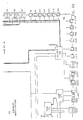
- FIG. 4 shows the overall architecture of the first, U1, Application Specific Integrated Circuit (ASIC) used within the preferred embodiment of the irrigation controller in accordance with the present invention.
- ASIC Application Specific Integrated Circuit
- the detail function of ASIC U1 is essentially unimportant for the purposes of the present invention, and is included within this specification only for purposes of completeness.
- the photovoltaic module (PVM, shown in Figure 6a), SUPERCAPS C1 and C2 (shown in Figure 6a) and ASIC U1 (shown in Figure 6a) may be considered to simply be the implementation of a special form of a light-energized power supply.
- the general implementation of an a.c. or battery source power supply is, of course, routine in the electrical arts.
- SUPERCAPS very large supercapacitors
- the U1 ASIC device is designed to use minimal power while providing five (5) functions:
- Sampling capacitors are used to monitor the various capacitor and power supply voltages, allowing the use of only one comparator to conserve current.
- CrSi 100 k ⁇ / resistors are used to minimize analog currents.
- the voltage reference is trimmed using on-chip metal fuses.
- CMOS circuitry There are 3 potential 'most positive' voltages and two potential 'most negative' voltages, making substrate connections difficult. This is handled by using bipolar junction isolation that employs the isolated n- regions as separate CMOS substrates. This allows the CMOS circuitry to operate from several supplies, any one of which could be at the highest potential at different times.
- the logic generally runs from VSS1 (OV) to VDD2 (0-5V), level shifting where required.
- Analog references run from VSS1 to VDD1 (0-11V).
- Switching regulator components run from VSS2 (-.7 to +5.5 V) to VBAT (0 to 15 V).
- the upper shunt transistor is connected to a voltage which can range from 0 to VDD1 +0.7V.
- FIG. 6 The block diagram of Figure 6, consisting of Figure 6a through Figure 6f, shows the overall architecture of the second, U2, Application Specific Integrated Circuit (ASIC) used within the preferred embodiment of the irrigation controller in accordance with the present invention.
- ASIC Application Specific Integrated Circuit
- the U2 ASIC device is concerned with calculation, command, and control. It is primarily digital in operation, and may be considered to be a specialized microprocessor with substantial analog as well as digital I/O capabilities.
- the diagram of the U2 ASIC device shows the detailed interconnection of the various functional blocks.
- the core microprocessor of the preferred embodiment of the invention is 100% compatible with industry standard type 6502. All firmware appended to this specification will execute on a 6502 microprocessor, and is readily convertible to alternative microinstruction repertoires executing on alternative microprocessors.
- the circuits by which data is manually input to the microprocessor and displayed, and the control of irrigation valves, are, in the preferred embodiment of the invention, powered and sequenced to states of activity in a highly unique manner. Nonetheless, it will be recognized that alternative implementations of these circuits, particularly as consume higher power and/or operate at higher or continuous duty cycles, are readily realizable by a practitioner of the electrical design arts. Accordingly, the present invention should be considered in terms of the functions that it performs, and not solely in terms of any particular embodiment for realizing these functions.
- the energy production, storage, and consumption balances of the system may be changed without departing from the spirit of the invention.
- the photovoltaic module could be made larger to gather more light energy.
- the energy storage in super capacitors could be differentially sized.
- the energy consumption could be set higher, especially if the controller is to be used in sunny climates.
Landscapes
- Engineering & Computer Science (AREA)
- Theoretical Computer Science (AREA)
- General Engineering & Computer Science (AREA)
- Environmental Sciences (AREA)
- General Physics & Mathematics (AREA)
- Physics & Mathematics (AREA)
- Water Supply & Treatment (AREA)
- Life Sciences & Earth Sciences (AREA)
- Human Computer Interaction (AREA)
- Power Engineering (AREA)
- Charge And Discharge Circuits For Batteries Or The Like (AREA)
- Gas-Insulated Switchgears (AREA)
- Direct Current Feeding And Distribution (AREA)
- Selective Calling Equipment (AREA)
- Arrangements For Transmission Of Measured Signals (AREA)
- Lasers (AREA)
Claims (10)
- Dispositif (1) pour alimenter en énergie un système qui à certains moments réalise une fonction qui diffère d'une communication qui consomme relativement moins de puissance, et qui à d'autres moments réalise une fonction de communication qui consomme relativement plus de puissance, caractérise par:
des moyens (PMV) pour dériver de l'énergie électrique à partir d'une énergie rayonnée, incidente sur le dispositif;
des moyens (SG1,SG2) pour stocker de l'énergie électrique, reçue en provenance des moyens pour dériver, pour alimenter en énergie le système pour sa fonction qui diffère d'une communication;
des moyens formant source d'alimentation transportable, reliés électriquement au dispositif pendant tous ces moments où le système réalise sa fonction de communication, pour alimenter en énergie le système sans diminution substantielle de l'énergie stockée dans les moyens pour stocker l'énergie. - Dispositif selon la revendication 1, dans lequel les moyens pour stocker comprennent:
un condensateur. - Dispositif selon la revendication 2, dans lequel le condensateur comprend:
un condensateur électrolytique ayant au moins une électrode en pâte de carbone. - Dispositif selon la revendication 2, dans lequel le condensateur comprend:
un condensateur électrique à double couche de grande capacité, stockant une charge au niveau d'une jonction au moyen d'un champ électrique entre une première phase comprenant une particule de carbone activée et une seconde phase comprenant de l'acide sulfurique. - Dispositif selon la revendication 1, dans lequel les moyens formant source d'alimentation transportable comprennent:
une batterie. - Dispositif selon la revendication 1 appliqué à l'alimentation en énergie d'un système de commande d'irrigation qui à certains moments réalise la fonction de commande d'irrigation qui consomme relativement moins de puissance et qui à d'autres moments réalise une fonction de communication vers un utilisateur/programmeur du système de commande d'irrigation afin que l'utilisateur/programmeur puisse diriger le système dans sa commande d'irrigation, dans lequel les moyens pour dériver comprennent:
un dispositif photovoltaïque dérivant de l'énergie électrique à partir d'une énergie lumineuse;
dans lequel les moyens pour stocker comprennent:
un condensateur;
et dans lequel les moyens formant source d'alimentation transportable comprennent:
une batterie. - Dispositif selon la revendication 1, dans lequel les moyens formant source d'alimentation transportable ne sont pas destinés seulement à alimenter en énergie le système sans diminution substantielle de l'énergie stockée dans les moyens pour stocker, mais aussi en fait à ravitailler l'énergie stockée dans les moyens pour stocker.
- Dispositif selon la revendication 1, dans lequel les moyens pour dériver comprennent:
une source d'alimentation photovoltaïque pour produire une tension en présence d'énergie lumineuse;
et dans lequel les moyens pour stocker comprennent:
un condensateur pour accumuler une charge électrique en réponse à la tension développée par la source d'alimentation photovoltaïque. - Système alimenté en énergie par un dispositif selon la revendication 1, dans lequel le système, bien que continuellement alimenté en énergie, présente des périodes substantielles pendant lesquelles il utilise une énergie insignifiante.
- Système selon la revendication 9, comprenant également:
une horloge pour indiquer le temps;
dans lequel les périodes substantielles du système pendant lesquelles une énergie insignifiante est utilisée sont définies par l'horloge.
Applications Claiming Priority (3)
| Application Number | Priority Date | Filing Date | Title |
|---|---|---|---|
| US253858 | 1988-10-04 | ||
| US07/253,858 US5229649A (en) | 1988-09-28 | 1988-10-04 | Light-energized electronics energy management system |
| PCT/US1989/004407 WO1990004871A1 (fr) | 1988-10-04 | 1989-10-04 | Systeme electronique de gestion energetique alimente en energie solaire |
Publications (3)
| Publication Number | Publication Date |
|---|---|
| EP0433400A1 EP0433400A1 (fr) | 1991-06-26 |
| EP0433400A4 EP0433400A4 (en) | 1992-05-20 |
| EP0433400B1 true EP0433400B1 (fr) | 1995-01-18 |
Family
ID=22961993
Family Applications (1)
| Application Number | Title | Priority Date | Filing Date |
|---|---|---|---|
| EP90901115A Expired - Lifetime EP0433400B1 (fr) | 1988-10-04 | 1989-10-04 | Systeme electronique de gestion energetique alimente en energie solaire |
Country Status (8)
| Country | Link |
|---|---|
| US (1) | US5229649A (fr) |
| EP (1) | EP0433400B1 (fr) |
| JP (1) | JPH04501200A (fr) |
| AT (1) | ATE117470T1 (fr) |
| AU (1) | AU4831690A (fr) |
| CA (1) | CA2000140A1 (fr) |
| DE (1) | DE68920746T2 (fr) |
| WO (1) | WO1990004871A1 (fr) |
Families Citing this family (50)
| Publication number | Priority date | Publication date | Assignee | Title |
|---|---|---|---|---|
| WO1993024982A1 (fr) * | 1992-05-27 | 1993-12-09 | Advanced Solar Technologies Pty. Ltd. | Unite de commande destinee a un appareil d'irrigation |
| US5748466A (en) * | 1995-09-08 | 1998-05-05 | L. R. Nelson | Adaptable control system for a variable number of switches |
| JPH09215319A (ja) | 1996-02-01 | 1997-08-15 | Toyota Autom Loom Works Ltd | Dc/dcコンバータ |
| US5912552A (en) | 1997-02-12 | 1999-06-15 | Kabushiki Kaisha Toyoda Jidoshokki Seisakusho | DC to DC converter with high efficiency for light loads |
| JPH10313572A (ja) | 1997-05-09 | 1998-11-24 | Toyota Autom Loom Works Ltd | スイッチングレギュレータ制御方式 |
| AR003907A1 (es) * | 1997-06-05 | 1998-09-30 | Rosenfeld Bernardo Raul | Sistema de riego ecologico autonomo |
| US6104759A (en) * | 1997-09-15 | 2000-08-15 | Research In Motion Limited | Power supply system for a packet-switched radio transmitter |
| US6335855B1 (en) | 1998-04-20 | 2002-01-01 | George Alexanian | Battery powered programmable remote switch controller |
| US5914847A (en) * | 1998-04-20 | 1999-06-22 | Alexanian; George | Programmable irrigation valve controller providing extended battery life |
| ITMI981244A1 (it) * | 1998-06-03 | 1999-12-03 | Lorenzo Ancona | Circuito monolitico computerizzato con funzioni programmabili in remoto collegabile ad attuatori e visualizzatori elettrici oppure a |
| RU2195754C2 (ru) * | 1999-09-01 | 2002-12-27 | Игорь Константинович Чернилевский | Устройство и способ отбора электрической энергии от солнечной батареи |
| TW457767B (en) * | 1999-09-27 | 2001-10-01 | Matsushita Electric Works Ltd | Photo response semiconductor switch having short circuit load protection |
| CA2363246C (fr) | 2000-11-06 | 2006-02-21 | Blackberry Limited | Chargeur de batteries portatif |
| US6946817B2 (en) * | 2001-03-01 | 2005-09-20 | Research In Motion Limited | System and method for powering and charging a mobile communication device |
| US6936936B2 (en) * | 2001-03-01 | 2005-08-30 | Research In Motion Limited | Multifunctional charger system and method |
| US7129493B2 (en) * | 2001-10-10 | 2006-10-31 | Ambient Control Systems, Inc. | Method and apparatus for photovoltaic cells of solar powered radiation sensing system antenna |
| US7256401B2 (en) * | 2001-10-10 | 2007-08-14 | Ambient Control Systems, Inc. | System and method for fire detection |
| WO2003031924A1 (fr) | 2001-10-10 | 2003-04-17 | Ambient Control Systems, Inc. | Systeme solaire a capteur de rayonnement bande etroite pour detecter et signaler les feux de foret |
| CA2427369A1 (fr) * | 2002-12-24 | 2004-06-24 | Research In Motion Limited | Methodes et appareils permettant de commander l'alimentation des circuits electriques d'un appareil de communications sans fil dote d'une interface de module d'identite d'abonne (sim) |
| AU2003900633A0 (en) * | 2003-02-13 | 2003-02-27 | Energy Storage Systems Pty Ltd | A resistive balance for an energy storage device |
| US7791319B2 (en) * | 2003-02-21 | 2010-09-07 | Research In Motion Limited | Circuit and method of operation for an electrical power supply |
| US6833686B2 (en) * | 2003-02-21 | 2004-12-21 | Research In Motion Limited | Circuit and method of operation for an adaptive charge rate power supply |
| US7826931B2 (en) * | 2005-09-15 | 2010-11-02 | Rain Bird Corporation | Integrated actuator coil and decoder module for irrigation control |
| US8851447B2 (en) | 2005-09-15 | 2014-10-07 | Rain Bird Corporation | Integrated control circuitry and coil assembly for irrigation control |
| US8840084B2 (en) | 2009-07-27 | 2014-09-23 | Rain Bird Corporation | Integrated control circuitry and coil assembly for irrigation control |
| US7525424B2 (en) * | 2006-08-15 | 2009-04-28 | Patented Technology Incorporated | Illuminated trail marker apparatus |
| US8055389B2 (en) | 2006-09-01 | 2011-11-08 | Dig Corporation | Method and apparatus for controlling irrigation |
| US20080157995A1 (en) * | 2006-12-29 | 2008-07-03 | Rain Bird Corporation | Irrigation two-wire communication control |
| US7856737B2 (en) * | 2007-08-28 | 2010-12-28 | Mathews Company | Apparatus and method for reducing a moisture content of an agricultural product |
| US8662471B2 (en) | 2008-03-31 | 2014-03-04 | Fujikin Incorporated | Solenoid valve |
| US8295985B2 (en) * | 2008-12-22 | 2012-10-23 | Rain Bird Corporation | Latching solenoid energy reserve |
| US8659183B2 (en) | 2009-07-17 | 2014-02-25 | Rain Bird Corporation | Variable initialization time in the charging of energy reserves in an irrigation control system |
| US8260465B2 (en) | 2009-07-17 | 2012-09-04 | Rain Bird Corporation | Data communication in a multi-wire irrigation control system |
| US20130197707A1 (en) * | 2011-06-23 | 2013-08-01 | Dispensing Dynamics International | Apparatus and method for harvesting and storing energy |
| US9032998B2 (en) | 2012-05-16 | 2015-05-19 | Dig Corporation | Method and apparatus for communicating irrigation data |
| US9305700B2 (en) * | 2012-10-04 | 2016-04-05 | Linear Technology Corporation | Auto resonant driver for wireless power transmitter sensing required transmit power for optimum efficiency |
| US9740258B2 (en) * | 2014-03-24 | 2017-08-22 | Intel Corporation | Hold-up energy storage and management |
| EP2946656A1 (fr) | 2014-05-21 | 2015-11-25 | Claber S.P.A. | Unité hybride de commande électronique d'irrigation de plantes |
| EP3261102A1 (fr) | 2016-06-23 | 2017-12-27 | Rain Bird Corporation | Solénoïde universel |
| US10980120B2 (en) | 2017-06-15 | 2021-04-13 | Rain Bird Corporation | Compact printed circuit board |
| CN107242107A (zh) * | 2017-07-24 | 2017-10-13 | 苏州普兆农业科技有限公司 | 一种光伏扬水灌溉系统 |
| US11503782B2 (en) | 2018-04-11 | 2022-11-22 | Rain Bird Corporation | Smart drip irrigation emitter |
| US11234380B2 (en) | 2018-09-27 | 2022-02-01 | Rain Bird Corporation | Irrigation controller with relays |
| CN109546683B (zh) * | 2018-12-12 | 2022-06-14 | 国网江苏省电力有限公司电力科学研究院 | 一种配电网节点分布式光伏接纳能力裕度优化方法 |
| CN111142654B (zh) * | 2019-12-27 | 2024-09-24 | 广州安凯微电子股份有限公司 | 一种多唤醒源输入的低功耗芯片架构系统及快速启动方法 |
| US11721465B2 (en) | 2020-04-24 | 2023-08-08 | Rain Bird Corporation | Solenoid apparatus and methods of assembly |
| IT202300025911A1 (it) | 2023-12-05 | 2025-06-05 | Claber Spa | Centralina di irrigazione off-grid ad energia solare senza batteria, in particolare centralina di irrigazione da rubinetto |
| IL322695A (en) | 2023-02-20 | 2025-10-01 | Claber Spa | Off-grid, solar-powered, battery-free irrigation control unit, specifically an irrigation control unit with a faucet. |
| CN116176326A (zh) * | 2023-03-17 | 2023-05-30 | 艺唯科技股份有限公司 | 一种电动汽车智能节能充电桩系统及充电优化方法 |
| CH721128A1 (de) * | 2023-09-14 | 2025-03-31 | Noderain Gmbh | Baueinheit und Baueinheiten-Bausatz zur Verwendung in einer Bewässerungsanlage für Pflanzen sowie eine derart ausgestattete Bewässerungsanlage |
Family Cites Families (13)
| Publication number | Priority date | Publication date | Assignee | Title |
|---|---|---|---|---|
| US3350618A (en) * | 1964-04-01 | 1967-10-31 | Space General Corp | Battery charging control |
| US3956638A (en) * | 1974-12-20 | 1976-05-11 | Hughes Aircraft Company | Battery paralleling system |
| JPS6024410B2 (ja) * | 1976-06-28 | 1985-06-12 | 日本電気株式会社 | 光電変換回路 |
| DE2632994A1 (de) * | 1976-07-22 | 1978-01-26 | Diehl Fa | Schalteinrichtung, vorzugsweise fuer die steuerung eines einem beregner vorgeschalteten ventils |
| US4165532A (en) * | 1977-12-30 | 1979-08-21 | The Toro Company | Automatic irrigation sprinkler system controller |
| US4775800A (en) * | 1983-12-30 | 1988-10-04 | Westinghouse Elctric Corp. | Power-supply apparatus |
| JPS6181141A (ja) * | 1984-09-25 | 1986-04-24 | シャープ株式会社 | 電源回路 |
| JPS61221530A (ja) * | 1985-03-19 | 1986-10-01 | シャープ株式会社 | 電子装置 |
| US4742291A (en) * | 1985-11-21 | 1988-05-03 | Bobier Electronics, Inc. | Interface control for storage battery based alternate energy systems |
| US4791948A (en) * | 1986-04-08 | 1988-12-20 | Bayat John J | Sprinkler control system |
| US4797820A (en) * | 1986-07-28 | 1989-01-10 | Ansan Industries Limited | Programmable flow control valve unit with clock, program, automatic, manual, and repeat modes |
| US4794272A (en) * | 1987-01-20 | 1988-12-27 | The Aerospace Corporation | Power regulator utilizing only battery current monitoring |
| SE461352B (sv) * | 1987-04-08 | 1990-02-05 | Aimpoint Ab | Stroemfoersoerjningskrets i foer skjutvapen avsedda riktmedel |
-
1988
- 1988-10-04 US US07/253,858 patent/US5229649A/en not_active Expired - Lifetime
-
1989
- 1989-10-04 DE DE68920746T patent/DE68920746T2/de not_active Expired - Fee Related
- 1989-10-04 EP EP90901115A patent/EP0433400B1/fr not_active Expired - Lifetime
- 1989-10-04 JP JP2501837A patent/JPH04501200A/ja active Pending
- 1989-10-04 WO PCT/US1989/004407 patent/WO1990004871A1/fr not_active Ceased
- 1989-10-04 CA CA002000140A patent/CA2000140A1/fr not_active Abandoned
- 1989-10-04 AU AU48316/90A patent/AU4831690A/en not_active Abandoned
- 1989-10-04 AT AT90901115T patent/ATE117470T1/de not_active IP Right Cessation
Also Published As
| Publication number | Publication date |
|---|---|
| DE68920746T2 (de) | 1995-06-22 |
| AU4831690A (en) | 1990-05-14 |
| US5229649A (en) | 1993-07-20 |
| JPH04501200A (ja) | 1992-02-27 |
| DE68920746D1 (de) | 1995-03-02 |
| CA2000140A1 (fr) | 1990-04-04 |
| EP0433400A4 (en) | 1992-05-20 |
| WO1990004871A1 (fr) | 1990-05-03 |
| ATE117470T1 (de) | 1995-02-15 |
| EP0433400A1 (fr) | 1991-06-26 |
Similar Documents
| Publication | Publication Date | Title |
|---|---|---|
| EP0433400B1 (fr) | Systeme electronique de gestion energetique alimente en energie solaire | |
| US5661349A (en) | Graceful energization and degradation of an electronic device micropowered by a source of energy in its environment, particularly an irrigation controller powered by light energy | |
| EP0399006B1 (fr) | Systeme de gestion centralise d'unites de commande multiples d'irrigation | |
| US5124942A (en) | Machine interface with cyclically displayed hierarchical menus and user selection of menu items by actuation of a single switch | |
| US8350519B2 (en) | Passive over/under voltage control and protection for energy storage devices associated with energy harvesting | |
| CN101872996A (zh) | 用于消耗和提供功率的高效系统和方法 | |
| US8055389B2 (en) | Method and apparatus for controlling irrigation | |
| WO1996015563A1 (fr) | Batterie intelligente | |
| US20120153747A1 (en) | Usb charger, its switch control system and method, and a usb interface charger for a laptop | |
| KR20010014816A (ko) | 태양 전지 장치 | |
| Boitier et al. | Battery-free power supply for wireless sensor combining photovoltaic cells and supercapacitors | |
| US5138185A (en) | Electrical backup interface device having low power output | |
| EP4275259A1 (fr) | Dispositif à énergie solaire utilisant un système et un procédé de gestion d'énergie | |
| CN210430987U (zh) | 单火线开关电池充电电路及应用此电路的供电装置 | |
| CN221374664U (zh) | 一种智能数字球阀的传感切换装置 | |
| CN113644716A (zh) | 一种5g新旧电池充电控制备电系统及控制方法 | |
| CN220797861U (zh) | 基于太阳能的供电设备和环境监测设备 | |
| Amin et al. | Development of cost effective charge controller with data acquisition options for PV powered sensor nodes | |
| Bálint | Development of a Low-Cost Solar Data Logger Using a PV Panel | |
| Azim et al. | Microcontroller based standalone PV system for wireless sensor node | |
| Santos | Optimised Photovoltaic Solar Charger With Voltage Maximum Power Point Tracking | |
| KR101052342B1 (ko) | 자기 전원 차단 기능을 구비하는 전자 장치 | |
| CN100380257C (zh) | 一种变压器降压的3+x转换式节电插座 | |
| Suzdalenko et al. | Evaluation of power consumption minimization approaches for autonomous electronic equipment | |
| CN119496269A (zh) | 基于太阳能的供电设备和环境监测设备 |
Legal Events
| Date | Code | Title | Description |
|---|---|---|---|
| PUAI | Public reference made under article 153(3) epc to a published international application that has entered the european phase |
Free format text: ORIGINAL CODE: 0009012 |
|
| 17P | Request for examination filed |
Effective date: 19901018 |
|
| AK | Designated contracting states |
Kind code of ref document: A1 Designated state(s): AT BE CH DE FR GB IT LI LU NL SE |
|
| RIN1 | Information on inventor provided before grant (corrected) |
Inventor name: LUCK, JONATHAN, M. Inventor name: NIELSEN, WYN, Y. |
|
| A4 | Supplementary search report drawn up and despatched |
Effective date: 19920402 |
|
| AK | Designated contracting states |
Kind code of ref document: A4 Designated state(s): AT BE CH DE FR GB IT LI LU NL SE |
|
| RIN1 | Information on inventor provided before grant (corrected) |
Inventor name: NIELSEN, WYN, Y. Inventor name: LUCK, JONATHAN, M. |
|
| 17Q | First examination report despatched |
Effective date: 19940113 |
|
| GRAA | (expected) grant |
Free format text: ORIGINAL CODE: 0009210 |
|
| AK | Designated contracting states |
Kind code of ref document: B1 Designated state(s): AT BE CH DE FR GB IT LI LU NL SE |
|
| PG25 | Lapsed in a contracting state [announced via postgrant information from national office to epo] |
Ref country code: IT Free format text: LAPSE BECAUSE OF FAILURE TO SUBMIT A TRANSLATION OF THE DESCRIPTION OR TO PAY THE FEE WITHIN THE PRESCRIBED TIME-LIMIT;WARNING: LAPSES OF ITALIAN PATENTS WITH EFFECTIVE DATE BEFORE 2007 MAY HAVE OCCURRED AT ANY TIME BEFORE 2007. THE CORRECT EFFECTIVE DATE MAY BE DIFFERENT FROM THE ONE RECORDED. Effective date: 19950118 Ref country code: LI Effective date: 19950118 Ref country code: FR Effective date: 19950118 Ref country code: NL Effective date: 19950118 Ref country code: AT Effective date: 19950118 Ref country code: BE Effective date: 19950118 Ref country code: CH Effective date: 19950118 |
|
| REF | Corresponds to: |
Ref document number: 117470 Country of ref document: AT Date of ref document: 19950215 Kind code of ref document: T |
|
| REF | Corresponds to: |
Ref document number: 68920746 Country of ref document: DE Date of ref document: 19950302 |
|
| PG25 | Lapsed in a contracting state [announced via postgrant information from national office to epo] |
Ref country code: SE Effective date: 19950418 |
|
| REG | Reference to a national code |
Ref country code: CH Ref legal event code: PL |
|
| EN | Fr: translation not filed | ||
| NLV1 | Nl: lapsed or annulled due to failure to fulfill the requirements of art. 29p and 29m of the patents act | ||
| PG25 | Lapsed in a contracting state [announced via postgrant information from national office to epo] |
Ref country code: GB Effective date: 19951004 |
|
| PG25 | Lapsed in a contracting state [announced via postgrant information from national office to epo] |
Ref country code: LU Free format text: LAPSE BECAUSE OF NON-PAYMENT OF DUE FEES Effective date: 19951031 |
|
| PLBE | No opposition filed within time limit |
Free format text: ORIGINAL CODE: 0009261 |
|
| STAA | Information on the status of an ep patent application or granted ep patent |
Free format text: STATUS: NO OPPOSITION FILED WITHIN TIME LIMIT |
|
| 26N | No opposition filed | ||
| GBPC | Gb: european patent ceased through non-payment of renewal fee |
Effective date: 19951004 |
|
| PG25 | Lapsed in a contracting state [announced via postgrant information from national office to epo] |
Ref country code: DE Effective date: 19960702 |