EP0433406B1 - Diving regulator demand valve - Google Patents
Diving regulator demand valve Download PDFInfo
- Publication number
- EP0433406B1 EP0433406B1 EP90908431A EP90908431A EP0433406B1 EP 0433406 B1 EP0433406 B1 EP 0433406B1 EP 90908431 A EP90908431 A EP 90908431A EP 90908431 A EP90908431 A EP 90908431A EP 0433406 B1 EP0433406 B1 EP 0433406B1
- Authority
- EP
- European Patent Office
- Prior art keywords
- air
- poppet
- valve
- regulator
- regulator according
- Prior art date
- Legal status (The legal status is an assumption and is not a legal conclusion. Google has not performed a legal analysis and makes no representation as to the accuracy of the status listed.)
- Expired - Lifetime
Links
- 230000009189 diving Effects 0.000 title description 4
- 230000029058 respiratory gaseous exchange Effects 0.000 claims abstract description 18
- 230000004044 response Effects 0.000 claims abstract description 7
- 210000004072 lung Anatomy 0.000 claims abstract description 3
- 239000000463 material Substances 0.000 claims description 2
- 229920003023 plastic Polymers 0.000 claims description 2
- 239000004033 plastic Substances 0.000 claims description 2
- 238000007789 sealing Methods 0.000 claims description 2
- 230000001419 dependent effect Effects 0.000 claims 1
- 230000000694 effects Effects 0.000 description 13
- 230000009471 action Effects 0.000 description 4
- 230000006872 improvement Effects 0.000 description 4
- 230000033228 biological regulation Effects 0.000 description 2
- 230000008859 change Effects 0.000 description 2
- 230000006835 compression Effects 0.000 description 2
- 238000007906 compression Methods 0.000 description 2
- 238000005336 cracking Methods 0.000 description 2
- 238000000034 method Methods 0.000 description 2
- 230000009467 reduction Effects 0.000 description 2
- 238000011144 upstream manufacturing Methods 0.000 description 2
- 206010028813 Nausea Diseases 0.000 description 1
- 230000010757 Reduction Activity Effects 0.000 description 1
- 230000004075 alteration Effects 0.000 description 1
- 230000008901 benefit Effects 0.000 description 1
- 230000003247 decreasing effect Effects 0.000 description 1
- 230000008030 elimination Effects 0.000 description 1
- 238000003379 elimination reaction Methods 0.000 description 1
- 238000012423 maintenance Methods 0.000 description 1
- 230000014759 maintenance of location Effects 0.000 description 1
- 230000004048 modification Effects 0.000 description 1
- 238000012986 modification Methods 0.000 description 1
- 230000008693 nausea Effects 0.000 description 1
- 230000008569 process Effects 0.000 description 1
Images


Classifications
-
- A—HUMAN NECESSITIES
- A62—LIFE-SAVING; FIRE-FIGHTING
- A62B—DEVICES, APPARATUS OR METHODS FOR LIFE-SAVING
- A62B9/00—Component parts for respiratory or breathing apparatus
- A62B9/02—Valves
- A62B9/022—Breathing demand regulators
-
- B—PERFORMING OPERATIONS; TRANSPORTING
- B63—SHIPS OR OTHER WATERBORNE VESSELS; RELATED EQUIPMENT
- B63C—LAUNCHING, HAULING-OUT, OR DRY-DOCKING OF VESSELS; LIFE-SAVING IN WATER; EQUIPMENT FOR DWELLING OR WORKING UNDER WATER; MEANS FOR SALVAGING OR SEARCHING FOR UNDERWATER OBJECTS
- B63C11/00—Equipment for dwelling or working underwater; Means for searching for underwater objects
- B63C11/02—Divers' equipment
- B63C11/18—Air supply
- B63C11/22—Air supply carried by diver
- B63C11/2227—Second-stage regulators
-
- Y—GENERAL TAGGING OF NEW TECHNOLOGICAL DEVELOPMENTS; GENERAL TAGGING OF CROSS-SECTIONAL TECHNOLOGIES SPANNING OVER SEVERAL SECTIONS OF THE IPC; TECHNICAL SUBJECTS COVERED BY FORMER USPC CROSS-REFERENCE ART COLLECTIONS [XRACs] AND DIGESTS
- Y10—TECHNICAL SUBJECTS COVERED BY FORMER USPC
- Y10T—TECHNICAL SUBJECTS COVERED BY FORMER US CLASSIFICATION
- Y10T137/00—Fluid handling
- Y10T137/7722—Line condition change responsive valves
- Y10T137/7738—Pop valves
-
- Y—GENERAL TAGGING OF NEW TECHNOLOGICAL DEVELOPMENTS; GENERAL TAGGING OF CROSS-SECTIONAL TECHNOLOGIES SPANNING OVER SEVERAL SECTIONS OF THE IPC; TECHNICAL SUBJECTS COVERED BY FORMER USPC CROSS-REFERENCE ART COLLECTIONS [XRACs] AND DIGESTS
- Y10—TECHNICAL SUBJECTS COVERED BY FORMER USPC
- Y10T—TECHNICAL SUBJECTS COVERED BY FORMER US CLASSIFICATION
- Y10T137/00—Fluid handling
- Y10T137/7722—Line condition change responsive valves
- Y10T137/7781—With separate connected fluid reactor surface
-
- Y—GENERAL TAGGING OF NEW TECHNOLOGICAL DEVELOPMENTS; GENERAL TAGGING OF CROSS-SECTIONAL TECHNOLOGIES SPANNING OVER SEVERAL SECTIONS OF THE IPC; TECHNICAL SUBJECTS COVERED BY FORMER USPC CROSS-REFERENCE ART COLLECTIONS [XRACs] AND DIGESTS
- Y10—TECHNICAL SUBJECTS COVERED BY FORMER USPC
- Y10T—TECHNICAL SUBJECTS COVERED BY FORMER US CLASSIFICATION
- Y10T137/00—Fluid handling
- Y10T137/7722—Line condition change responsive valves
- Y10T137/7781—With separate connected fluid reactor surface
- Y10T137/7782—With manual or external control for line valve
Definitions
- the present invention relates to self contained underwater breathing apparatus and more specifically relates to improvements in regulators associated therewith whereby the breathing characteristics in a regulator are altered so as to reduce the inhalation effort required by a user upon demand for air.
- the alteration in the breathing characteristics is effected according to the present invention by adjustments to the demand valve in the regulator.
- Regulators are well known in the diving industry as a crucial component of the apparatuses required.
- a regulator acts in concert with a pressure reducing valve and as a means for regulation of air for a diver.
- the pressure reduction activity is known as the first stage of regulation and this involves the reduction in air pressure between the air tank and the regulator.
- the supply of air upon demand by a diver passes through the first stage thence through a second stage.
- the second stage of operation is controlled by a demand valve which is located near the air discharge end of the regulator which comprises a mouthpiece.
- Swiss patent document No CH 466051 describes a regulator corresponding to the preamble of claim 1, having a poppet valve.
- the poppet is operated by a lever which is operated by a diaphragm which moves in response to demand for air from the user of the regulator.
- the poppet has a flange that is biased to close an inlet, and a balancing means, attached to the flange, in the bore upstream of the flange.
- the arrangement is such that when the valve is closed, the tendency of the air pressure on the flange to open the inlet is opposed by a pressure on the balancing means, whereby the force from the lever required to open the poppet is independent of the air pressure in the bore and is set solely by the biasing means.
- Regulators are well known with numerous designs for these being readily available.
- a typical regulator comprises a housing having a mouthpiece and a demand valve which acts in concert with a vacuum assisted diaphragm located inside the housing.
- the diaphragm is, and consequently the demand valve, are operably responsive to demand for air.
- the demand valve is typically adapted with an internal element known as a poppet which is adapted to operate between a closed and open position in response to demand for air by a user.
- the poppet when in the closed position is urged against an air inlet hole in the valve under the assistance of a spring bias closing off the supply of air via the inlet.
- the compression force in the spring must be at least slightly greater than the pressure exerted immediately upstream of the inlet orifice to enable the closing of the orifice.
- the poppet moves from the closed configuration to an open configuration upon demand for air.
- unbalanced forces are generated due to the gradient of increasing effort required to overcome the increasing compressive force exerted by the spring bias when demand is made for air by the user.
- the cracking effort When a user of a regulator demands air the initial inhalation effort is called the cracking effort. That is, the effort required to move the sealing end of the poppet away from the air inlet.
- the cracking effort required is generally a function of the dynamic air pressure acting on the end of the poppet at the air inlet end of the valve relative to the energy in the biasing spring coupled with the degree of vacuum required to overcome the counteracting spring force upon demand for air.
- the air travel is also affected by a venturi effect created when air is demanded due to the high velocity of the air.
- the prior art poppet arrangement suffers from the major disadvantage that an unbalanced force regime is generated at the air entry orifice and within the valve chamber due to the prior art configuration of the typical poppet.
- the present invention seeks to ameliorate or eliminate the unbalanced forces existing in the prior art demand valves by providing a newly configured demand valve which results in balanced forces in the valve and a reduced effort on the part of the user when demanding air.
- valve is adapted with a concentric sleeve operable by a knob external of the housing to enable adjustment by a user when in use of the air passage such that the vacuum can be cancelled to conserve air or to adjust venturi flow so as to direct air into the mouthpiece of the regulator.
- the prior art regulators could only be adjusted by use of a screw driver or like instrument.
- the present invention comprises; a breathing regulator for use in underwater breathing, comprising: a primary housing with a breathing chamber, a valve, and a diaphragm that moves in response to a vacuum in the breathing chamber, the valve comprising: an inlet and an outlet and a flow path within the valve enabling travel of air between the inlet and the outlet and thence to an outlet in the housing and, via a mouth piece, the lungs of a user, and a poppet slidably mounted in the valve to open and close said flow path, the poppet including an elongate member having first and second ends, means for so biasing the poppet against the inlet of the valve as to close the flow path,means for moving the poppet in response to movement of the diaphragm, and characterised in that the poppet comprises at least one air baffle on or integral with the elongate member and located intermediate its ends, and closure means at the first end of the elongate member being arranged to abut the inlet when air is not being demanded by
- the closure means for the flow path may comprise the end of the elongate member.
- the first end of the elongate member may be provided with a further baffle for closing the inlet, said baffle having an area less than the cross sectional area of the flow path in said valve but greater in area than the cross sectional area of the air inlet to thereby act as a closure for said inlet when said poppet is in the closed position and as an air baffle when said poppet is in the open position.
- the means for moving the poppet may comprise a lever arm which engages the second end of the poppet.
- the valve preferably comprises a venturi assisted air directing means comprising a concentric sleeve that is disposed about the valve and has an opening therein which can be selectively partly or wholly aligned with the outlet of the valve.
- the purpose of the sleeve is to facilitate more efficient air delivery to the user following exiting of the air from the housing.
- the sleeve also enables selective control of air by the user external of the housing either to enhance the venturi flow of air or to cancel the effect of the vacuum according to user requirements.
- the concentric sleeve may be operable via a knob external of the regulator. The selective adjustment of the mechanical sleeve via said knob may alter the direction of the air either towards or away from the mouthpiece of the regulator.
- the concentric sleeve may be made from a plastics material. The said knob may have associated therewith graduations indicating the available settings for said concentric sleeve.
- the at least one baffle intermediate the ends of the elongate member may comprise two spaced apart baffles disposed approximately midway between the ends of said elongate member.
- the arrangement may be such that when the poppet is in the fully open position said baffle or baffles are located at or near said valve outlet so that air continues to impinge on said baffle or baffles immediately prior to exiting from said outlet thereby creating a balance between the biasing force and the line pressure force in said valve.
- the air may impinge predominantly on the front surface of each of said baffles.
- the means for providing the bias may comprise a helical spring.
- the biasing spring may be concentric with a portion of said poppet and engages a surface on one of said baffles.
- the biasing spring may engage the second end of said poppet.
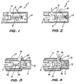
- FIG. 1 there is shown a portion of a prior art demand valve 1 comprising a housing 2 having an inlet opening 3 and an outlet opening 4.
- the demand valve also comprises within the housing a poppet 5 shown in the closed position and being urged against the mouth of orifice 3 under the biasing action of helical spring 6.
- Figure 2 shows the demand valve of figure 1 however, this time the poppet 5 is shown drawn away from the area of inlet opening 3 so as to enable air to pass within cavity 7 of the housing 2.
- the force regime is such that the compressive force generated by the spring 6 is at least slightly larger than the force generated by the air pressure at the inlet opening 3. This results in the poppet 5 being urged against the opening 3 to thereby close off the opening when air is not required.
- Figure 3 shows a portion of a demand valve according to the preferred embodiment of the present invention showing a newly configured poppet 10 and an externally adjustable outer concentric sleeve 17 which assists in directing air flow to the mouth of the user.
- the demand valve of figure 3 comprises a valve housing 8 having there within an inlet orifice 9 similar to the inlet orifice 3 of the prior art valve in figure 1.
- the valve also contains a poppet 10 which is urged against the orifice of inlet opening 9 under the assistance of biasing spring 11.
- the valve also has a conventional lever 12 which is actuated by linkage to the valve and which is responsive to the action by vacuum assistance of a regulator diaphragm (see figures 5 and 6) upon demand for air by a user of the demand valve.
- the demand valve of the present invention differs in one respect from the prior art according to one embodiment by firstly comprising a newly configured poppet 10.
- the poppet 10 comprises an elongated shaft 13 having located thereon or thereabout a first baffle or flange 14 and a second baffle or flange 15.
- the configuration of this poppet results in a change in the force regime which occurs around the poppet upon demand for air by a user of the demand valve.
- Figure 3 shows the demand valve according to the present invention with the poppet in the closed position.
- the action of the diaphragm in the regulator causes arm 12 to allow passage of air through inlet opening 9.
- the configuration of the demand valve in the open position is shown in figure 4.
- the effect of the forces so generated cause an increase of and/or a maintenance of pressure in the flange or baffle 15 at the same time as deflection of air is caused by and about flange 14. At this time air is also escaping via outlet orifice 16 located in the wall of the housing 8 and via orifice 19 located in concentric sleeve 17.
- the configuration of the poppet 10 is such that the air can only either escape through exit 16 or alternatively impinge upon the surface of baffle 15.
- the impingement of the air on baffle 15 has the effect of countering the increase in the size of the biasing force exerted by spring 11 as it is compressed under the action of the air pressure.
- the impinging air on baffle 15 also compensates for air loss through orifice 16. The overall result of this effect is to reduce the effort required by the user demanding air due to the air line forces being maintained on the poppet thereby enabling optimum force balance.
- FIG 5 there is shown a cross sectional plan view of a regulator having a demand valve 20 shown in the configuration commensurate with exhalation by a user.
- the demand valve 20 is shown poppet 21 urged against orifice 22 such that the orifice 22 is sealed by poppet end 23.
- Line pressure from a supply tank (not shown) is exerted in supply line 24 usually the line pressure exerted in line 24 would be at or around 28 pounds force.
- biasing spring 25 urges the end of the poppet 26 in a direction contrary to that exerted by the line pressure on the end 23 of the poppet 21.
- the pressure exerted by the biasing spring 25 should be as close as possible to the line pressure but slightly above the line pressure so that when air is not demanded the poppet remains in the closed configuration.
- Figure 6 shows the regulator of figure 5 this time in the air demand or inhalation configuration when a user demands air.
- the end 23 of the poppet 21 is drawn away from the orifice under the assistance of the vacuum created in chamber 27 by diaphragm 28.
- the spring bias force is ideally slightly greater than the line pressure, a further effort is required to be exerted on the poppet 21 to move it away from the orifice 22 to thereby allow free flow of air to mouthpiece 29.
- the flange 30 which is located around the main shaft 31 of the poppet 21.
- the line pressure had no effect in urging a force against the poppet once the poppet had released from the supply orifice.
- the provision of the flange 30 provides a surface on which the incoming air can impinge thereby enabling retention of the line pressure on the poppet to urge the poppet away from the inlet orifice thereby reducing the effort required by the user upon demand for air.
- FIGS 5 and 6 show a flange on the poppet according to one embodiment it is envisaged that the flange can be made up from one or more of a plurality of flanges provided obstruction is provided to the air incoming from the orifice 22 and passage via orifice 32 to the mouthpiece 29. Ideally the flange would be located when the poppet is in the fully open configuration at or near orifice 32 so that air is contemporaneously impinging on the flange 31 and redirected via orifice 32 into the mouthpiece 29.
- the improved valve also comprises a concentric sleeve 17 (see figures 3 and 4) adapted to concentrically rotate about housing 8.
- the housing 8 may be fixedly attached to the sleeve 17 so that the whole demand valve portion can rotate as one. This allows the facility for directing the air towards the mouth piece of the regulator thus facilitating improved passage of air and without the assistance of baffles as was required in the prior art.
- Figure 7 shows an abbreviated cross sectional elevational view of the prior art configuration of the regulator showing a baffle used for deflection of air.
- the attitude of the baffle is selected according to the angle the air is to impinge on the baffle.
- FIG 8 shows a cross sectional view of a regulator showing the venturi assist facility in the demand valve of the present invention located therein. Also in this regulator, it can be noted that the baffle is absent with the air being directed via rotational freedom of the demand valve so that the user may select the direction of air which leaves the demand valve, according to air demand requirements.
- baffle arrangement for air delivery as shown in figure 7 in the cross section of the regulator is that the baffle or screen can work to obstaculate the passage of air towards the mouth piece of the regulator. It can also result in drag on the air due to the change in direction thus slowing down entry of the air into the mouth piece of the regulator.
- This problem is overcome by the elimination of the baffle and also by the facility imparted to the demand valve of the present invention whereby it can be rotated within the regulator by external selective orientation of the directional passage of air towards the mouth piece of the regulator. With the rotational ability of the demand valve as shown in figure 6, it is possible that air could be directed any where within the range of 0 to 360° thereby resulting in freer passage of air to the mouth of a user.
- FIG 9 there is shown a side elevational cross sectional view of a regulator 33 having a demand valve 34 whereby air exits the demand valve in the direction of arrow 35 into the mouthpiece 36.
- Figure 10 shows the regulator 33 this time with the demand valve 34 reconfigured so that air travels in the direction of arrows 37 so that the vacuum effect created in chamber 38 by means of diaphragm 39 is counteracted.
- a control of the demand valve 34 is effected by means of a sleeve 40 which is operable by means of a knob 41 which is external to the regulator 33. This enables a user to alter the direction of air in the mouthpiece during use.
- the demand valve arrangement of the present invention enables a user to make an air boost selection at any time during use by means of the external knob 41. This enhances a venturi effect of high velocity air when required and it may also counteract the vacuum effect created in chamber 38 by diaphragm 39 when a user demands air through the mouthpiece 36.
- figure 9 shows the configuration of the demand valve 34 when maximum air delivery would be presented to mouthpiece 36.
- Figure 10 shows the demand valve 34 with the configuration of sleeve 40, disposed so that air delivery to mouthpiece 36 is at a minimum. A selection of the configuration as shown in figure 10 would be likely to be made by an operator when less air is required.
- the improvement to the demand valve can stop this by restricting the amount of air free flowing to the user thus, the valve can be adjusted to personal requirements according to air demand.
Landscapes
- Health & Medical Sciences (AREA)
- Pulmonology (AREA)
- General Health & Medical Sciences (AREA)
- Business, Economics & Management (AREA)
- Emergency Management (AREA)
- Engineering & Computer Science (AREA)
- Mechanical Engineering (AREA)
- Ocean & Marine Engineering (AREA)
- Respiratory Apparatuses And Protective Means (AREA)
- Water Treatment By Sorption (AREA)
- Feeding And Controlling Fuel (AREA)
- Magnetically Actuated Valves (AREA)
- Valve Device For Special Equipments (AREA)
- Fluid-Driven Valves (AREA)
Priority Applications (1)
| Application Number | Priority Date | Filing Date | Title |
|---|---|---|---|
| EP94119661A EP0649783A1 (en) | 1989-06-06 | 1990-06-06 | Diving regulator demand valve |
Applications Claiming Priority (3)
| Application Number | Priority Date | Filing Date | Title |
|---|---|---|---|
| AU4577/89 | 1989-06-06 | ||
| AUPJ457789 | 1989-06-06 | ||
| PCT/AU1990/000249 WO1990014990A1 (en) | 1989-06-06 | 1990-06-06 | Diving regulator demand valve |
Related Child Applications (1)
| Application Number | Title | Priority Date | Filing Date |
|---|---|---|---|
| EP94119661.0 Division-Into | 1994-12-13 |
Publications (3)
| Publication Number | Publication Date |
|---|---|
| EP0433406A1 EP0433406A1 (en) | 1991-06-26 |
| EP0433406A4 EP0433406A4 (en) | 1991-12-27 |
| EP0433406B1 true EP0433406B1 (en) | 1995-09-27 |
Family
ID=3773968
Family Applications (2)
| Application Number | Title | Priority Date | Filing Date |
|---|---|---|---|
| EP90908431A Expired - Lifetime EP0433406B1 (en) | 1989-06-06 | 1990-06-06 | Diving regulator demand valve |
| EP94119661A Ceased EP0649783A1 (en) | 1989-06-06 | 1990-06-06 | Diving regulator demand valve |
Family Applications After (1)
| Application Number | Title | Priority Date | Filing Date |
|---|---|---|---|
| EP94119661A Ceased EP0649783A1 (en) | 1989-06-06 | 1990-06-06 | Diving regulator demand valve |
Country Status (9)
| Country | Link |
|---|---|
| US (2) | US5437268A (da) |
| EP (2) | EP0433406B1 (da) |
| AT (1) | ATE128428T1 (da) |
| AU (1) | AU644794B2 (da) |
| DE (1) | DE69022697T2 (da) |
| DK (1) | DK0433406T3 (da) |
| ES (1) | ES2080144T3 (da) |
| NZ (2) | NZ245967A (da) |
| WO (1) | WO1990014990A1 (da) |
Families Citing this family (29)
| Publication number | Priority date | Publication date | Assignee | Title |
|---|---|---|---|---|
| EP0534741B1 (en) * | 1991-09-26 | 1996-11-13 | Dacor Corporation | Breathing regulator having air injector feature |
| US5233976A (en) * | 1992-04-27 | 1993-08-10 | Dacor Corporation | Second stage regulator hose with built-in cone adjusting tool |
| IT1271095B (it) * | 1994-11-24 | 1997-05-26 | Scubapro Europ | Erogatore per autorespiratori subacquei |
| US5803073A (en) * | 1996-03-08 | 1998-09-08 | Toth; Douglas J. | Second stage scuba diving regulator having a pneumatic-dependent anti-set feature |
| US5791373A (en) * | 1996-04-29 | 1998-08-11 | Adams; John S. | Fluid sealing disc and seat mechanism |
| US5970977A (en) * | 1997-10-15 | 1999-10-26 | Harsco Technologies Corporation | Demand regulator having adjustable air flow |
| DE19934057A1 (de) * | 1999-07-19 | 2001-02-01 | Auergesellschaft Gmbh | Ventil für Druckgasatemgeräte |
| DE19934058B4 (de) * | 1999-07-19 | 2004-07-08 | Auergesellschaft Gmbh | Ventil für Druckgasatemgeräte |
| JP3281339B2 (ja) * | 1999-09-24 | 2002-05-13 | 株式会社タバタ | ダイビング用レギュレーター |
| GB0112958D0 (en) * | 2001-05-29 | 2001-07-18 | F X K Patents Ltd | A pressure regulator |
| DE10126633B4 (de) * | 2001-05-31 | 2005-11-24 | Heptec Gmbh | Atemventil für CPAP-Geräte |
| US6601609B2 (en) * | 2001-06-01 | 2003-08-05 | Shane S. Taylor | Fluid flow control valve |
| US6554023B2 (en) | 2001-06-13 | 2003-04-29 | Baxter International Inc. | Vacuum demand flow valve |
| US6550493B2 (en) | 2001-06-13 | 2003-04-22 | Baxter International Inc. | Vacuum demand valve |
| US6863261B2 (en) | 2002-03-12 | 2005-03-08 | Baxter International Inc. | Valve stop |
| DE10222750C1 (de) * | 2002-05-23 | 2003-11-06 | Walter Schmidt | Vorrichtung zur Inhalation einer vorgegebenen Menge an Kohlenmonoxid |
| ITFI20030199A1 (it) * | 2003-07-25 | 2005-01-26 | Cressi Sub Spa | Valvola secondaria perfezionata per sommozzatore. |
| US7171980B2 (en) * | 2004-06-18 | 2007-02-06 | Johnson Outdoors Inc. | Springless regulator valve assembly |
| FR2903654B1 (fr) | 2006-07-13 | 2008-09-05 | Spirotechnique Sa | Dispositif d'alimentation en gaz respiratoire, notamment pour un embout buccal de plongeur |
| FR2904962B1 (fr) * | 2006-08-16 | 2008-10-03 | Spirotechnique Sa | Dispositif de detente pour l'alimentation en gaz respirable d'un plongeur |
| GB2443392B (en) * | 2006-11-01 | 2011-06-08 | Clipper Data Ltd | Pressure regulator valve for breathing apparatus |
| NZ586099A (en) | 2007-11-19 | 2012-05-25 | Carefusion 2200 Inc | Patient interface assembly comprising a jet pump including a venturi assembly defining an entrainment region, a throat region and an expansion region |
| IT1393518B1 (it) * | 2009-03-30 | 2012-04-27 | Scubapro Europ | Erogatore per uso subacqueo |
| US20110155771A1 (en) * | 2009-08-10 | 2011-06-30 | Brooks Dennis L | Method and apparatus for enabling smoother, faster discharge of fluid from containers |
| US20110132939A1 (en) * | 2009-08-10 | 2011-06-09 | Brooks Dennis L | Method and Apparatus for Enabling Smoother, Faster Discharge of Fluid from Containers |
| US9067038B2 (en) * | 2009-08-31 | 2015-06-30 | William A. Leffel | Valve system for use with a flexible gas supply tube extending to a patient |
| US8011380B2 (en) * | 2009-10-01 | 2011-09-06 | Vision Tech International Llp | Single component two-stage regulator |
| KR101292866B1 (ko) * | 2010-09-19 | 2013-08-02 | 박은태 | 유체배출장치 |
| CN103742653B (zh) * | 2013-12-24 | 2016-06-22 | 江苏爵格工业设备有限公司 | 一种气密阀 |
Family Cites Families (20)
| Publication number | Priority date | Publication date | Assignee | Title |
|---|---|---|---|---|
| CH194284A (de) * | 1935-08-28 | 1937-11-30 | Degea Ag Auerg | Ventil für Atemgeräte, insbesondere für solche mit lungenselbsttätigem Sauerstoffzuführungsventil. |
| CH216130A (de) * | 1939-11-25 | 1941-07-31 | Heinrich Dr Draeger Otto | Lungenselbsttätig wirkende Ventileinrichtung mit Sauerstoffzuführungsventil für Sauerstoffatemgeräte ohne konstante Dosierung. |
| US2571007A (en) * | 1947-07-31 | 1951-10-09 | United Eng Foundry Co | Relief valve |
| US2667893A (en) * | 1950-02-03 | 1954-02-02 | Air Associates Inc | Relief valve |
| US2695609A (en) * | 1952-01-28 | 1954-11-30 | Garrett Corp | Breathing apparatus |
| US2767726A (en) * | 1953-06-23 | 1956-10-23 | Westinghouse Air Brake Co | Pilot actuated compensating pressure regulator |
| US2763262A (en) * | 1955-01-19 | 1956-09-18 | Garrett Corp | Source selector for breathing apparatus |
| US3028860A (en) * | 1957-02-27 | 1962-04-10 | Spirotechnique | Reserve disposal arrangement for breathing apparatus |
| US3044484A (en) * | 1959-06-08 | 1962-07-17 | Wilsons Sons Inc William M | By-pass valves |
| US3053271A (en) * | 1960-06-22 | 1962-09-11 | Jr Eugene C Crittenden | Sampling pressure regulator |
| FR1355755A (fr) * | 1963-02-07 | 1964-03-20 | Aqua Sport | Dispositif perfectionné pour appareil respiratoire notamment pour utilisations sous-marines |
| CH466051A (de) * | 1968-03-05 | 1968-11-30 | Stirnemann Peter | Pressluft-Atmungsgerät |
| US4076041A (en) * | 1974-09-23 | 1978-02-28 | Christianson Raymond | Pilot valve operated demand regulator for a breathing apparatus |
| US4147176A (en) * | 1975-06-30 | 1979-04-03 | Christianson Raymond | Diaphragm assembly for the demand regulator of a breathing apparatus |
| US4503852A (en) * | 1981-08-24 | 1985-03-12 | Tony Christianson | Pilot controlled regulator second stage |
| US4616645A (en) * | 1985-05-24 | 1986-10-14 | Dacor Corporation | Diving regulator with anti free-flow vane |
| US4796618A (en) * | 1986-01-21 | 1989-01-10 | Undersea Industries, Inc. | Breathing regulator apparatus |
| FR2594786B1 (fr) * | 1986-02-21 | 1988-05-13 | Spirotech Ind Commerc | Appareil respiratoire a air comprime pour la plongee sous-marine |
| IT1200310B (it) * | 1986-10-30 | 1989-01-12 | Righetti Flavio E Drafinsub Sr | Battello semovente per il disinquinamento di specchi d acqua e suo funzionamento |
| IT211686Z2 (it) * | 1987-01-28 | 1989-04-07 | Amf Mares Spa | Dispositivo regolare di pressione per il secondo stadio di riduzione degli apparecchi respiratori ad aria |
-
1990
- 1990-06-06 ES ES90908431T patent/ES2080144T3/es not_active Expired - Lifetime
- 1990-06-06 DE DE69022697T patent/DE69022697T2/de not_active Expired - Fee Related
- 1990-06-06 NZ NZ245967A patent/NZ245967A/en unknown
- 1990-06-06 EP EP90908431A patent/EP0433406B1/en not_active Expired - Lifetime
- 1990-06-06 WO PCT/AU1990/000249 patent/WO1990014990A1/en not_active Ceased
- 1990-06-06 EP EP94119661A patent/EP0649783A1/en not_active Ceased
- 1990-06-06 AU AU57350/90A patent/AU644794B2/en not_active Ceased
- 1990-06-06 DK DK90908431.1T patent/DK0433406T3/da active
- 1990-06-06 AT AT90908431T patent/ATE128428T1/de not_active IP Right Cessation
- 1990-06-06 NZ NZ233968A patent/NZ233968A/en unknown
-
1993
- 1993-06-03 US US08/071,946 patent/US5437268A/en not_active Expired - Fee Related
-
1995
- 1995-07-28 US US08/508,364 patent/US5735269A/en not_active Expired - Fee Related
Also Published As
| Publication number | Publication date |
|---|---|
| ATE128428T1 (de) | 1995-10-15 |
| US5437268A (en) | 1995-08-01 |
| EP0433406A4 (en) | 1991-12-27 |
| ES2080144T3 (es) | 1996-02-01 |
| DE69022697D1 (de) | 1995-11-02 |
| WO1990014990A1 (en) | 1990-12-13 |
| DK0433406T3 (da) | 1996-02-12 |
| NZ233968A (en) | 1994-08-26 |
| EP0433406A1 (en) | 1991-06-26 |
| EP0649783A1 (en) | 1995-04-26 |
| NZ245967A (en) | 1994-08-26 |
| AU5735090A (en) | 1991-01-07 |
| DE69022697T2 (de) | 1996-05-15 |
| AU644794B2 (en) | 1993-12-23 |
| US5735269A (en) | 1998-04-07 |
Similar Documents
| Publication | Publication Date | Title |
|---|---|---|
| EP0433406B1 (en) | Diving regulator demand valve | |
| US5065746A (en) | Expiration valve control arrangement for a ventilating apparatus | |
| US4219017A (en) | Pilot regulator | |
| US4640277A (en) | Self-contained breathing apparatus | |
| US5259375A (en) | Second stage scuba regulator with balanced piston volume control | |
| EP0691137B1 (en) | Gas mixing devices for resuscitation/lung ventilation apparatus | |
| US5931163A (en) | Valve for setting the flow of a flow medium | |
| EP0451090B1 (en) | Resuscitation and ventilation device | |
| EP0726862B1 (en) | A valve arrangement and a breathing regulator which includes such a valve arrangement | |
| US7775208B2 (en) | Device for supplying breathing gas, particularly for mouthpiece of a diver | |
| GB1586716A (en) | Breathing apparatus | |
| JPH0265862A (ja) | 制御可能な呼吸弁 | |
| US4446859A (en) | Breathing apparatus | |
| JPS6039597B2 (ja) | 要求調節器で用いるダイヤフラムアセンブリ | |
| US5222490A (en) | Breathing regulator having air injector feature | |
| US4041977A (en) | Breathing apparatus flow regulator | |
| EP0901400A1 (en) | Improved breathing regulator apparatus having automatic flow control | |
| US5970977A (en) | Demand regulator having adjustable air flow | |
| US5660502A (en) | Adjustment mechanism for a scuba second stage airflow regulator | |
| US4140113A (en) | Breathing apparatus | |
| AU664250B2 (en) | Improvements in diving regulator demand valve | |
| US5701890A (en) | Regulator provided with a movable deflector | |
| EP0534741B1 (en) | Breathing regulator having air injector feature | |
| JP2765594B2 (ja) | ダイビング・レギュレータ | |
| US4182323A (en) | Breathing apparatus |
Legal Events
| Date | Code | Title | Description |
|---|---|---|---|
| PUAI | Public reference made under article 153(3) epc to a published international application that has entered the european phase |
Free format text: ORIGINAL CODE: 0009012 |
|
| AK | Designated contracting states |
Kind code of ref document: A1 Designated state(s): AT BE CH DE DK ES FR GB IT LI LU NL SE |
|
| 17P | Request for examination filed |
Effective date: 19910611 |
|
| A4 | Supplementary search report drawn up and despatched |
Effective date: 19911106 |
|
| AK | Designated contracting states |
Kind code of ref document: A4 Designated state(s): AT BE CH DE DK ES FR GB IT LI LU NL SE |
|
| 17Q | First examination report despatched |
Effective date: 19930309 |
|
| GRAA | (expected) grant |
Free format text: ORIGINAL CODE: 0009210 |
|
| AK | Designated contracting states |
Kind code of ref document: B1 Designated state(s): AT BE CH DE DK ES FR GB IT LI LU NL SE |
|
| REF | Corresponds to: |
Ref document number: 128428 Country of ref document: AT Date of ref document: 19951015 Kind code of ref document: T |
|
| XX | Miscellaneous (additional remarks) |
Free format text: TEILANMELDUNG 94119661.0 EINGEREICHT AM 13/12/94. |
|
| REF | Corresponds to: |
Ref document number: 69022697 Country of ref document: DE Date of ref document: 19951102 |
|
| ITF | It: translation for a ep patent filed | ||
| REG | Reference to a national code |
Ref country code: CH Ref legal event code: NV Representative=s name: A. BRAUN, BRAUN, HERITIER, ESCHMANN AG PATENTANWAE |
|
| REG | Reference to a national code |
Ref country code: ES Ref legal event code: FG2A Ref document number: 2080144 Country of ref document: ES Kind code of ref document: T3 |
|
| REG | Reference to a national code |
Ref country code: DK Ref legal event code: T3 |
|
| ET | Fr: translation filed | ||
| PLBE | No opposition filed within time limit |
Free format text: ORIGINAL CODE: 0009261 |
|
| STAA | Information on the status of an ep patent application or granted ep patent |
Free format text: STATUS: NO OPPOSITION FILED WITHIN TIME LIMIT |
|
| 26N | No opposition filed | ||
| REG | Reference to a national code |
Ref country code: GB Ref legal event code: IF02 |
|
| PGFP | Annual fee paid to national office [announced via postgrant information from national office to epo] |
Ref country code: GB Payment date: 20050601 Year of fee payment: 16 |
|
| PGFP | Annual fee paid to national office [announced via postgrant information from national office to epo] |
Ref country code: DE Payment date: 20050602 Year of fee payment: 16 |
|
| PGFP | Annual fee paid to national office [announced via postgrant information from national office to epo] |
Ref country code: NL Payment date: 20050605 Year of fee payment: 16 |
|
| PGFP | Annual fee paid to national office [announced via postgrant information from national office to epo] |
Ref country code: SE Payment date: 20050607 Year of fee payment: 16 |
|
| PGFP | Annual fee paid to national office [announced via postgrant information from national office to epo] |
Ref country code: FR Payment date: 20050608 Year of fee payment: 16 |
|
| PGFP | Annual fee paid to national office [announced via postgrant information from national office to epo] |
Ref country code: AT Payment date: 20050613 Year of fee payment: 16 |
|
| PGFP | Annual fee paid to national office [announced via postgrant information from national office to epo] |
Ref country code: DK Payment date: 20050614 Year of fee payment: 16 |
|
| PGFP | Annual fee paid to national office [announced via postgrant information from national office to epo] |
Ref country code: CH Payment date: 20050615 Year of fee payment: 16 |
|
| PGFP | Annual fee paid to national office [announced via postgrant information from national office to epo] |
Ref country code: LU Payment date: 20050622 Year of fee payment: 16 |
|
| PGFP | Annual fee paid to national office [announced via postgrant information from national office to epo] |
Ref country code: ES Payment date: 20050728 Year of fee payment: 16 |
|
| PGFP | Annual fee paid to national office [announced via postgrant information from national office to epo] |
Ref country code: BE Payment date: 20050810 Year of fee payment: 16 |
|
| PG25 | Lapsed in a contracting state [announced via postgrant information from national office to epo] |
Ref country code: GB Free format text: LAPSE BECAUSE OF NON-PAYMENT OF DUE FEES Effective date: 20060606 Ref country code: AT Free format text: LAPSE BECAUSE OF NON-PAYMENT OF DUE FEES Effective date: 20060606 |
|
| PG25 | Lapsed in a contracting state [announced via postgrant information from national office to epo] |
Ref country code: SE Free format text: LAPSE BECAUSE OF NON-PAYMENT OF DUE FEES Effective date: 20060607 Ref country code: ES Free format text: LAPSE BECAUSE OF NON-PAYMENT OF DUE FEES Effective date: 20060607 |
|
| PG25 | Lapsed in a contracting state [announced via postgrant information from national office to epo] |
Ref country code: LI Free format text: LAPSE BECAUSE OF NON-PAYMENT OF DUE FEES Effective date: 20060630 Ref country code: DK Free format text: LAPSE BECAUSE OF NON-PAYMENT OF DUE FEES Effective date: 20060630 Ref country code: CH Free format text: LAPSE BECAUSE OF NON-PAYMENT OF DUE FEES Effective date: 20060630 Ref country code: BE Free format text: LAPSE BECAUSE OF NON-PAYMENT OF DUE FEES Effective date: 20060630 |
|
| PGFP | Annual fee paid to national office [announced via postgrant information from national office to epo] |
Ref country code: IT Payment date: 20060630 Year of fee payment: 17 |
|
| PG25 | Lapsed in a contracting state [announced via postgrant information from national office to epo] |
Ref country code: NL Free format text: LAPSE BECAUSE OF NON-PAYMENT OF DUE FEES Effective date: 20070101 |
|
| PG25 | Lapsed in a contracting state [announced via postgrant information from national office to epo] |
Ref country code: DE Free format text: LAPSE BECAUSE OF NON-PAYMENT OF DUE FEES Effective date: 20070103 |
|
| REG | Reference to a national code |
Ref country code: DK Ref legal event code: EBP |
|
| REG | Reference to a national code |
Ref country code: CH Ref legal event code: PL |
|
| EUG | Se: european patent has lapsed | ||
| GBPC | Gb: european patent ceased through non-payment of renewal fee |
Effective date: 20060606 |
|
| NLV4 | Nl: lapsed or anulled due to non-payment of the annual fee |
Effective date: 20070101 |
|
| REG | Reference to a national code |
Ref country code: FR Ref legal event code: ST Effective date: 20070228 |
|
| REG | Reference to a national code |
Ref country code: ES Ref legal event code: FD2A Effective date: 20060607 |
|
| BERE | Be: lapsed |
Owner name: T.D. *PREECE & CO. PTY. LTD Effective date: 20060630 |
|
| PG25 | Lapsed in a contracting state [announced via postgrant information from national office to epo] |
Ref country code: FR Free format text: LAPSE BECAUSE OF NON-PAYMENT OF DUE FEES Effective date: 20060630 |
|
| PG25 | Lapsed in a contracting state [announced via postgrant information from national office to epo] |
Ref country code: LU Free format text: LAPSE BECAUSE OF NON-PAYMENT OF DUE FEES Effective date: 20060606 |
|
| PG25 | Lapsed in a contracting state [announced via postgrant information from national office to epo] |
Ref country code: IT Free format text: LAPSE BECAUSE OF NON-PAYMENT OF DUE FEES Effective date: 20070606 |