EP0433470B1 - Bürstenstopfvorrichtung und Verfahren zu deren Gebrauch - Google Patents
Bürstenstopfvorrichtung und Verfahren zu deren Gebrauch Download PDFInfo
- Publication number
- EP0433470B1 EP0433470B1 EP89123376A EP89123376A EP0433470B1 EP 0433470 B1 EP0433470 B1 EP 0433470B1 EP 89123376 A EP89123376 A EP 89123376A EP 89123376 A EP89123376 A EP 89123376A EP 0433470 B1 EP0433470 B1 EP 0433470B1
- Authority
- EP
- European Patent Office
- Prior art keywords
- filling
- tool
- brush
- tuft
- turret
- Prior art date
- Legal status (The legal status is an assumption and is not a legal conclusion. Google has not performed a legal analysis and makes no representation as to the accuracy of the status listed.)
- Expired - Lifetime
Links
- 238000000034 method Methods 0.000 title claims description 5
- 239000000835 fiber Substances 0.000 claims description 81
- 230000004323 axial length Effects 0.000 claims description 2
- 125000006850 spacer group Chemical group 0.000 claims description 2
- 230000001419 dependent effect Effects 0.000 description 2
- 230000001133 acceleration Effects 0.000 description 1
- 230000004308 accommodation Effects 0.000 description 1
- 230000006978 adaptation Effects 0.000 description 1
- 230000000737 periodic effect Effects 0.000 description 1
- 238000009966 trimming Methods 0.000 description 1
- 238000011144 upstream manufacturing Methods 0.000 description 1
Images
Classifications
-
- A—HUMAN NECESSITIES
- A46—BRUSHWARE
- A46D—MANUFACTURE OF BRUSHES
- A46D3/00—Preparing, i.e. Manufacturing brush bodies
- A46D3/04—Machines for inserting or fixing bristles in bodies
- A46D3/042—Machines for inserting or fixing bristles in bodies for fixing bristles using an anchor or staple
Definitions
- the present invention relates to a brush filling machine and to a method of operating the brush filling machine.
- Modern brush filling machines have a rotary turret mounted in a machine frame and having four lateral brush body gripping faces. Each brush body gripping face of the turret is successively supplied with a brush body, indexed by an angle of e.g. 90° to be presented to a filling tool and then indexed to a position where the filled brush bodies are removed from the turret and taken over by a take-off system.
- the spacing between two adjacent brush bodies on each laterial gripping face of the turret is in turn determined by the required spacing between the pair of filling tools.
- the spacing between the pair of filling tools is determined by the space requirements of each filling tool and its associated operating units.
- These operating units include a fiber tuft supply box, a tuft picker for feeding individual fiber tufts from the fiber tuft supply box to the associated filling tool in each filling stroke,an anchor wire feed system with an associated punch member for supplying individual anchors to the filling tool for each fiber tuft to be anchored in a brush body, and a tuft driver member for driving each fiber tuft and the associated anchor into the brush body.
- the present invention provides a brush filling machine wherein the spacing of two adjacent brush bodies on each lateral gripping face of the turret is reduced to a minimum value so that the indexing speed of the turret can be increased.
- the specific arrangement of the various operating units of the inventive brush filling machine allows the pair of filling tools to have a minimum spacing from each other so that the corresponding spacing of the pair of brush bodies on the lateral gripping faces of the turret can be correspondingly reduced.
- the present invention provides a brush filling machine having a frame, a rotary turret mounted in the frame, a brush body feeding system for supplying brush bodies to the turret, a take-off system for removing filled brush bodies from the turret and a pair of filling tools having their fiber tuft delivery openings facing one of a plurality of lateral gripping faces of the turret, each gripping face of the turret having gripping means for releasably holding a pair of adjacent brush bodies;
- the brush filling machine being characterized in that the pair of filling tools have their tool slides slidably mounted in a common filling tool box in a parallel and adjacent relationship, both tool slides of the pair being connected to a common tool slide drive,that each filling tool has an anchor wire feed channel extending transverse to the direction of sliding movement of the tool slides and opening next to the opposed faces of two adjacent tool slides, each filling tool having a punch member mounted for reciprocating movement in the filling tool box transverse to the sliding movement direction
- each filling tool has a tuft picker member reciprocatingly pivoting about a common axis parallel to the axis of reciprocating movement of said punch members, the tuft picker members being parallel and spaced from each other and being connected to a common tuft picker drive, and in that each tuft picker member cooperates with an associated fiber supply box, the fiber supply boxes of both filling tools being mounted on top of each other.
- a strand of parallel fibers is supplied to each filling tool from a spool or a number of spools transverse to the sliding movement of the tool slides, and a tuft cutter is associated with each filling tool to cut off individual fiber tufts from the fiber strand, said tuft cutters being connected to a common tuft cutter drive.
- the specific arrangement of the various operating units, i.e. the tool slides, the fiber tuft supply boxes and the anchor wire feed channels with the associated punch members, is optimized to minimize the required spacing between the pair of filling tools.
- the brush bodies on each lateral gripping face of the turret to have a minimum spacing from each other thereby reducing the radial dimensions of the turret.
- the radial dimensions of the turret are the governing parameter with respect to the maximum attainable indexing speed of the turret.
- the indexing speed of the turret is compatible with the operating speed of the filling tools. This means that the filling tools can be operated continuously without waiting for presenting a new pair of brush bodies after the filling of a preceding pair of brush bodies has been completed.
- the present invention provides a method of operating a brush filling machine of the type defined above, wherein two brush bodies are supplied to one lateral gripping face of the turret while two other brush bodies are being filled with fiber tufts on an adjacent lateral gripping face of the turret and two further, filled brush bodies are removed from a further lateral gripping face of the turret, the turret being indexed after each completed brush body filling cycle to present a new pair of brush bodies to be filled with fiber tufts to the filling tools, each of the filling tools performing one of successive filling strokes for each fiber tuft to be anchored in the respective brush body; the method being characterized in that the indexing of the turret is performed within the time of one of the filling strokes so that indexing of the turret causes no wait state of the filling tools.
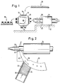
- the brush filling machine schematically shown in Fig. 1 has a rotary turret 10 mounted in a machine frame 12.
- the turret 10 has four lateral gripping faces 14 dimensioned to accommodate a pair of adjacent brush bodies 16 to be filled with fiber tufts.
- a brush body feeding system 18 supplies pairs of brush bodies 16 to the respectively upper lateral gripping face 14 of the turret 10.
- the turret 10 is adapted to be indexed in steps of 90° rotation in a clockwise sense in Fig. 1 to present its gripping face 14 supplied with fresh brush bodies 16 to a pair of filling tools 20, 22 mounted in a common filling tool box 24.
- the turret 10 is again indexed to present new brush bodies to the pair of filling tools 20, 22 and to present a pair of filled brushes to a take-off system 26 which will normally transport the filled brushes to further processing units of the machine, for example to a trimming station where the ends of the fiber tufts are trimmed to the desired length.
- adjacent brush bodies 16 on a lateral gripping face 14 of the turret 10 are spaced from each other by a minimum amount which is determined by the spacing a between the longitudinal axis of the filling tools 20, 22.
- the specific arrangement of the various operating units of the inventive brush filling machine as will be disclosed in detail with reference to Figs. 2 to 14, allows the spacing a to be minimized, thereby reducing the radial dimension of the rotary turret 10, i.e. the dimension which governs the maximum attainable indexing speed of the turret.
- the common filling tool box 24 may be formed of a single body or casing, or composed of two assembled filling tool box parts which are each associated with one filling tool.
- Fig. 2 shows the relationship between the upper filling tool 20, the associated tuft picker unit 30 and the corresponding fiber tuft box 32.
- the fiber supply box 32 contains many individual fibers 34 in an upright position which are urged by a pressure device 36 against the arcuate outer surface of tuft picker member 38.
- the tuft picker member 38 is mounted for pivotal reciprocating movement along the path described by its arcuate outer surface so that a notch 40 formed in this outer surface passes in front of the fiber supply box 32 to pick off a tuft of fibers which are then introduced into a gap 42 of the filling tool 20.
- a notch 40 formed in this outer surface passes in front of the fiber supply box 32 to pick off a tuft of fibers which are then introduced into a gap 42 of the filling tool 20.
- the filling tool has a central channel which opens on the front tip and which receives individual fiber tufts via the gap 42.
- an anchor cut off from an anchor wire is introduced into the central channel, and a tuft driver member slidingly received in the rear part of the central channel of the filling tool 20 is periodically advanced to drive each fiber tuft with its anchor through the forward portion of the central channel and out of its end on the tool tip and into an opposed hole of a brush body 16.
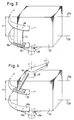
- each filling tool has its associated tuft picker member 38, 38a.
- the tuft picker members 38, 38a are interconnected by a spacer 44.
- Tuft picker member 38a is connected to one arm 46 of a two-armed lever 48 which is pivotally mounted on the lower side of the filling tool box 24.
- the other arm of the two-armed lever 48 is connected to a conventional tuft picker drive (not shown).
- each tuft picker member 38, 38a has its own holding arm (46, 46a) on an associated two-armed lever 48, 48a,the other arm of lever 48, 48a being connected to a common conventional tuft picker drive (not shown).
- the two-armed levers 48, 48a are pivotally mounted on the opposed upper and lower faces of the filling tool box 24.
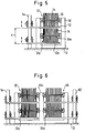
- Fig. 5 shows the arrangement of the fiber supply boxes associated with the pair of filling tools 20, 22.
- a common frame 50 is provided for defining two fiber supply boxes 32, 32a on top of each other.
- the fibers 34 are received in an upright position in each fiber supply box and rest with their lower ends on an associated bottom plate 52, 52a, the bottom plates 52, 52a being carried by a stand 54 mounted on the machine frame 12.
- the bottom plates 52, 52a are individually or simultaneously adjustable in height for adaptation to different lengths of fibers 34. The height of each bottom plate 52, 52a is adjusted so that the center of the fibers 34 is on the level of the central axis 20a, 22a of the corresponding filling tool 20, 22.
- each fiber supply box 32, 32a has an associated pressure device 36, 36a for urging the fibers 34 against the associated tuft picker member 38, 38a.
- Fig. 6 The embodiment of Fig. 6 is generally similar to that of Fig. 5, but there is a pair of fiber supply boxes 32, 60 and 32a, 60a associated with each filling tool 20, 22.
- a common frame 50a is provided which carries the two pairs of fiber supply boxes 32, 60 and 32a, 60a.
- An additional stand 62 is provided for carrying the bottom plates of the additional fiber supply boxes 60, 60a.
- the additional fiber supply boxes 60, 60a can receive fibers different in nature, for example in length or color, from the fibers used in fiber supply boxes 32, 32a. Each brush body can thus be filled with different types of fiber tufts. If the length of the fibers in fiber supply boxes 60, 60a is different from that of the fibers in fiber supply boxes 32, 32a, the respective bottom plates are adjusted to different heights.
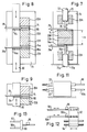
- Fig. 7 shows a first embodiment of an arrangement of a pair of punch members in a schematic cross-section.
- the purpose of the punch members is to cut off short ends of a continuous anchor wire to provide the anchors required for fixing the fiber tufts in the holes of the brush bodies.
- the filling tool box 24 has a pair of aligned guiding channels 70, 70a in its opposed top and bottom walls for slidingly receiving a punch shaft 72, 72a connected to a reciprocating punch drive (not shown). Both punch shafts 72, 72a are preferably connected to the same punch drive.
- each filling tool has a tool slide composed of a pair of slide members 20A, 20B and 22A, 22B.
- Each of the slide members 20A, 20B, 22A, 22B is slidingly received in a corresponding longitudinal channel of the filling tool box 24.
- the slide members 20B, 22B are directly adjacent each other and on top of each other in the center zone of the filling tool box 24, while slide members 20A, 22A are respectively accommodated in the top and bottom regions of the filling tool box 24.
- Cutting plates 74, 74a are located on the opposed sides of slide members 20B, 22B. Each cutting plate 74, 74a cooperates with a punch member 76, 76a integrally formed with an associated punch shaft 72, 72a.
- a continuous anchor wire 78, 78a is fed through a transverse feed channel to a central position of each cutting plate 74, 74a where the cutting plates have a hole which corresponds in shape to the free end of the corresponding punch member 76, 76a.
- the punch members 76, 76a have cut off a short end from the continuous anchor wire 78, 78a and pushed the cut off end through the hole in the cutting plate 74, 74a to a level which corresponds to the center axis of the corresponding filling tool 20, 22, i.e. to the center channel thereof.
- the spacing between the opposed faces of slide members 20B, 22B is the spacing a between the axes of the filling tools 20, 22 (Fig. 1).
- a single punch bar 80 cooperates with both filling tools 20, 22.
- each filling tool slide has a lateral recess 82 for accommodation of the punch bar 80, the recess 82 having an axial length substantially corresponding to the operating stroke of the filling tool.
- Each lateral recess 82 extends radially inwardly to the axial center channel of the tool slide.
- the punch bar 80 carries two spaced punch plates 84, 84a for cooperation with a laterally adjacent cutting plate 74, 74a associated with slide member 20A, 22B.
- a guiding plate 86, 86a is located below each cutting plate 74, 74a to define a slit wherein the end tip of the continuous anchor wire 78, 78a is introduced.
- each punch plate 84, 84a passes across the associated slit to cut off the end tip of the anchor wire 78, 78a in each operating stroke of the associated filling tool.
- Fig. 9 shows the position of the punch bar 80 after having cut off the end tip of the continuous anchor wire.
- each filling tool has a tool slide composed of two slide members which are axially movable with respect to each other.
- the tuft receiving gap 42 (Fig. 2) can be closed after the introduction of each each fiber tuft to facilitate the passing of the anchor cut off from the continuous anchor wire.
- each filling tool has a single slide member
- the slide members of the two filling tools are preferably driven in synchronism if they are not rigidly connected with each other or form an integral unit.
- the tuft receiving gap 42 (Fig.2) is not closed but remains open: The anchor is only held on one side of the center channel of the respective filling tool when the anchor is passing through it. The other side is open, but the dimension of the opening is kept small enough so that the anchor will not drop out.
- the slide members of both filling tools are rigidly connected with each other or even provided as a single integral unit.
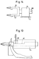
- Fig. 11 shows the tuft driver members 90, 90a extending from the rearward end of the filling tools 20, 22.
- the outer ends of the tuft driver members 90, 90a are individually connected to a common actuator 92 mounted for reciprocating movement on guide rails 94, through a respective load sensing contact pair 96, 96a the contacts of which are separated by a pressure spring as shown in Fig. 12.
- the outer ends of the tuft driver members 90, 90a are interconnected by a bridge member 98 which is in turn connected to the actuator 92 of Fig. 12 through a single load sensing contact pair 96.
- the force of the spring separating the associated contact pair is overcome and the contacts are closed. Closure of the contacts may be detected to sense an overload condition and to enable an appropriate corrective function, for example a standstill of the machine permitting an operator to remove the cause of the overload.
- Fig. 14 shows an alternative embodiment wherein both filling tools 20, 22 are connected to a common tool slide 100 mounted for reciprocating movement in the filling tool box 24.
- the brush filling machine of the present invention is adapted to be operated in a specific manner which is permitted by the described arrangement of the various operating units of the machine.
- each filling tool performs a number of operating strokes corresponding to the number of fiber tufts to be anchored in the brush body.
- the rotary turret 10 is indexed to present a pair of fresh brush bodies to be filled.
- the periodic operation of the filling tools 20, 22, of the tuft picker units, the punch members and the tuft driver members is not interrupted and not even retarded.
- the preferred embodiment has a turret designed to be indexed at 90° steps, other embodiments can be envisaged wherein the indexing step is more or less than 90°, for example 120° for a turret having three lateral brush body gripping faces.
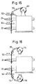
- the fiber tufts are not supplied from a fiber box where individually cut lengths of fiber are accommodated, but supplied as a strand of fibers to each filling tool. More specifically, and referring to Fig. 15, a continuous strand 100 of individual fibers the number of which corresponds to the number of fibers in each tuft is supplied to the pair of filling tools 20, 22 transverse to their slide members to pass in front of the respective fiber gap.
- the fiber strand 100 can be supplied from a single spool 101 or from a number of individual spools (not shown) each accommodating a single continuous fiber.
- a tuft cutter 102, 104 is associated with each filling tool to cut off two successive lengths from the end of the fiber strand 100 to provide fiber tufts of the required length to each of the filling tools 20, 22.
- the spacing between the filling tools 20, 22 is adjusted to its minimum possible value, the two lengths of strand which are simultaneously cut from the fiber strand 100 by the tuft cutters 102, 104 are adjacent to each other, and only one cut is required for each tuft to be severed from the strand.
- Synchronism of operation between the pair of tuft cutters 102, 104 is obtained by connecting them to a common cutter drive (not shown).
- an individual strand of fibers 110, 112 is supplied to each filling tool 20, 22 from a respective spool 114, 116, and each tuft cutter 102, 104 is provided upstream from its associated filling tool.
- Figs. 15 and 16 do not require a tuft picker and a fiber box and are, in this respect, less complex than the embodiments of Figs. 1 to 14.
Landscapes
- Engineering & Computer Science (AREA)
- Manufacturing & Machinery (AREA)
- Brushes (AREA)
- Preliminary Treatment Of Fibers (AREA)
Claims (19)
- Bürstenstopfmaschine mit einem Rahmen (12), einem im Rahmen (12) angebrachten, drehbaren Revolverkopf (10), einem Bürstenkörper-Zufuhrsystem (18) zum Versorgen des Revolverkopfes (10) mit Bürstenkörpern (16), einem Entnahmesystem (26) zum Entfernen der gestopften Bürstenkörper (16) vom Revolverkopf (10) und einem Paar Stopfwerkzeuge (20, 22), deren Faserbüschel-Abgabeöffnungen einer von mehreren seitlichen Greifflächen (14) des Revolverkopfes (10) gegenüberliegen, wobei jede Greiffläche (14) des Revolverkopfes (10) Greifmittel zum lösbaren Halten eines Paares von angrenzenden Bürstenkörpern (16) enthält, dadurch gekennzeichnet, daß das Paar der Stopfwerkzeuge (20, 22) seine Werkzeugschlitten (20A, 20B, 22A, 22B) verschiebbar in einem gemeinsamen Stopfwerkzeugkasten (24) zueinander parallel und aneinander angrenzend angebracht besitzt, wobei beide Werkzeugschlitten des Paares mit einem gemeinsamen Werkzeugschlittenantrieb verbunden sind, daß jedes Stopfwerkzeug (20, 22) einen Zufuhrkanal für Ankerdraht (78, 78a) besitzt, der sich quer zur Verschieberichtung der Werkzeugschlitten erstreckt und der neben den gegenüberliegenden Seiten von zwei benachbarten Werkzeugschlitten geöffnet ist, wobei jedes Stopfwerkzeug (20, 22) ein Stanzelement (76, 76a; 84, 84a) besitzt, das zur Ausführung einer hin- und hergehenden Bewegung in dem Stopfwerkzeugkasten (24) quer zur Gleitbewegungsrichtung der Werkzeugschlitten angebracht ist und angrenzend an das offene Ende eines zugeordneten Ankerdraht-Zufuhrkanals eine Schneide besitzt, daß jedes Stopfwerkzeug ein Büschelgreifelement (38, 38a) besitzt, das um eine gemeinsame, zur Achse der hin- und hergehenden Bewegung des Stanzelements parallelen Achse hin- und herschwenkt, wobei die Büschelgreifelemente (38, 38a) zueinander parallel und voneinander beabstandet sind sowie mit einem gemeinsamen Büschelgreiferantrieb verbunden sind, und daß jedes Büschelgreifelement mit einem zugeordneten Faserversorgungskasten (32, 32a) zusammenwirkt, wobei die Faserversorgungskästen der beiden Stopfwerkzeuge (20, 22) übereinanderliegend angebracht sind.
- Bürstenstopfmaschine mit einem Rahmen (12), einem im Rahmen (12) angebrachten, drehbaren Revolverkopf (10), einem Bürstenkörper-Zufuhrsystem (18) zum Versorgen des Revolverkopfes (10) mit Bürstenkörpern (16), einem Entnahmesystem (26) zum Entfernen der gestopften Bürstenkörper (16) vom Revolverkopf (10) und einem Paar Stopfwerkzeuge (20, 22), deren Faserbüschel-Abgabeöffnungen einer von mehreren seitlichen Greifflächen (14) des Revolverkopfes (10) gegenüberliegen, wobei jede Greiffläche (14) des Revolverkopfes (10) Greifmittel zum lösbaren Halten eines Paares von angrenzenden Bürstenkörpern (16) enthalt, dadurch gekennzeichnet, daß das Paar der Stopfwerkzeuge (20, 22) seine Werkzeugschlitten (20A, 20B, 22A, 22B) verschiebbar in einem gemeinsamen Stopfwerkzeugkasten (24) zueinander parallel und aneinander angrenzend angebracht besitzt, wobei beide Werkzeugschlitten des Paares mit einem gemeinsamen Werkzeugschlittenantrieb verbunden sind, daß jedes Stopfwerkzeug (20, 22) einen Zufuhrkanal für Ankerdraht (78, 78a) besitzt, der sich quer zur Verschieberichtung der Werkzeugschlitten erstreckt und der neben den gegenüberliegenden Seiten von zwei benachbarten Werkzeugschlitten geöffnet ist, wobei jedes Stopfwerkzeug (20, 22) ein Stanzelement (76, 76a; 84, 84a) besitzt, das zur Ausführung einer hin- und hergehenden Bewegung in dem Stopfwerkzeugkasten (24) quer zur Gleitbewegungsrichtung der Werkzeugschlitten angebracht ist und angrenzend an das offene Ende eines zugeordneten Ankerdraht-Zufuhrkanals eine Schneide besitzt, daß jedem Stopfwerkzeug (20, 22) von einer Spule (101; 114, 116) oder von einer Anzahl von Spulen quer zur Gleitrichtung der Werkzeugschlitten eine durchgehende Litze (100, 110, 112) von parallelen Fasern zugeführt wird und daß jedem Stopfwerkzeug (20, 22) ein Büschelschneider (102, 104) zugeordnet ist, um individuelle Faserbüschel von der Faserlitze (100; 110, 112) abzuschneiden, wobei die Büschelschneider (102, 104) mit einem gemeinsamen Büschelschneiderantrieb verbunden sind.
- Bürstenstopfmaschine nach Anspruch 1 oder 2, bei der die Stanzelemente (76, 76a; 84, 84a) miteinander ausgerichtete Achsen besitzen.
- Bürstenstopfmaschine nach einem der Ansprüche 1 bis 3, bei der jedes Stopfwerkzeug (20, 22) ein Büschelantriebselement (90, 90a) besitzt, das verschiebbar in einem axialen Kanal des entsprechenden Werkzeugschlittens aufgenommen ist, wobei beide Büschelantriebselemente mit einem gemeinsamen Betätigungselement verbunden sind.
- Bürstenstopfmaschine nach einem der Ansprüche 1, 3 und 4, bei der ein erstes der Büschelgreifelemente (38, 38a) mit einem Schwenkarm (46) verbunden ist und ein zweites der Büschelgreifelemente mittels eines Distanzstückes (44) mit dem ersten Büschelgreifelement verbunden ist, wobei der Schwenkarm (46) zum Ausführen einer hin- und hergehenden Schwenkbewegung an einer Seite des Stopfwerkzeugkastens (24) angebracht ist.
- Bürstenstopfmaschine nach einem der Ansprüche 1, 3 und 4, bei der jedes Büschelgreifelement (38, 38a) mit einem zugeordneten Schwenkarm (46) verbunden ist, wobei beide Schwenkarme zum Ausführen einer hin- und hergehenden Schwenkbewegung an einer der beiden zueinander entgegengesetzten Seiten des Stopfwerkzeugkastens (24) angebracht sind.
- Bürstenstopfmaschine nach einem der vorhergehenden Ansprüche, bei der jeder Werkzeugschlitten ein Paar zusammenwirkende, wechselseitig axial verschiebbare Schlittenelemente (20A, 20B, 22A, 22B) enthalt.
- Bürstenstopfmaschine nach Anspruch 6, bei der ein Schlittenelement (20B) des Schlittenelementpaares von einem der Werkzeugschlitten direkt an der Spitze von einem Schlittenelement (22B) des Schlittenelementpaares des anderen Werkzeugschlittens angebracht ist.
- Bürstenstopfmaschine nach Anspruch 7, bei der das andere Schlittenelement (20A) des Schlittenelementpaares von jedem Werkzeugschlitten eine Öffnung besitzt, durch die sich der Schaft (72, 72a) eines zugeordneten Stanzelementstabes (76, 76a) erstreckt, wobei an der Seite des einen Schlittenelementes (20B, 22B) von jedem Paar, die dem anderen Schlittenelement (20A, 22B) von jedem Paar zugewandt ist, eine Schneidplatte (74, 74a) angebracht ist, die mit dem Stanzelement (76, 76a) zusammenwirkt.
- Bürstenstopfmaschine nach einem der Ansprüche 1 bis 7, bei der jeder Werkzeugschlitten eine seitliche Vertiefung (82) mit einer axialen Länge besitzt, die im wesentlichen dem Arbeitshub des Werkzeugschlittens entspricht, wobei die seitliche Vertiefung (82) sich radial nach innen zu einem axialen Mittenkanal des Werkzeugschlittens erstreckt und einen Stanzstab (80) aufnimmt, der verschiebbar in dem Stopfwerkzeugkasten (24) angebracht ist, und wobei der Stanzstab (80) das Stanzelement (84, 84a) trägt.
- Bürstenstopfmaschine nach Anspruch 9, bei der der Stanzstab (80) einen Endabschnitt besitzt, in dem jeder der Zufuhrkanäle des Ankersdrahts (78, 78a) ausgeformt ist und dessen eine Seite durch eine Stanzplatte (84, 84a) bestimmt ist.
- Bürstenstopfmaschine nach Anspruch 10, bei der die Stanzplatte (84, 84a) angrenzend an eine Schneide der Schneidplatte (74, 74a) einen Rand besitzt, wobei die Schneidplatte zwischen zwei einander gegenüberliegenden Führungsplatten (86, 86a) und einem angrenzenden Werkzeugschlittenelement (20A, 22B) angeordnet ist, wobei die Führungsplatte und die Schneidplatte einen Spalt zum Aufnehmen von einer Endspitze des Ankerdrahtes (78, 78a) bestimmen, die von der Stanzplatte an der Schneide abgeschnitten wird, wenn der Stanzstab (80) in hin- und hergehender Weise bewegt wird.
- Bürstenstopfmaschine nach Anspruch 11, bei der jede der Führungsplatten (86, 86a) mit seiner zur Schneidplatte (74, 74a) entgegengesetzten Seite an ein angrenzendes Werkzeugschlittenelement (20B, 22A) in Anlage gerät.
- Bürstenstopfmaschine nach einem der Ansprüche 1 und 3 bis 13, bei der jeder der Faserversorgungskästen (32, 32a) eine untere Platte (52, 52a) besitzt, die in der Höhe einstellbar ist.
- Bürstenstopfmaschine nach einem der Ansprüche 1 und 3 bis 14, bei der jedes Stopfwerkzeug (20, 22) einem Paar von Faserversorgungskästen (32, 60; 32a, 60a) zugeordnet ist, die Seite an Seite auf der gleichen Höhe angeordnet sind, um zwei Arten von Fasern (34) aufzunehmen.
- Bürstenstopfmaschine nach einem der Ansprüche 4 bis 13, bei der die Büschelantriebselemente (90, 90a) mit einem gemeinsamen Betätigungselement (92) über Beladungserfassungsmittel (96, 96a) verbunden sind, wobei die Beladungserfassungsmittel Kontaktmittel enthalten, die beim Erfassen einer vorbestimmten, maximalen Beladung ein Signal bereitstellen, das eine korrigierende Funktion ermöglicht.
- Bürstenstopfmaschine nach Anspruch 15, bei der jedes Büschelantriebselement (90, 90a) individuell mit dem Betätigungselement (92) über ein zugeordnetes Beladungserfassungsmittel (96, 96a) verbunden ist.
- Bürstenstopfmaschine nach Anspruch 15, bei der die Büschelantriebselemente (90, 90a) miteinander durch ein Brückenelement (98) an ihren äußeren, freien Enden verbunden sind, wobei das Brückenelement mit dem Betätigungselement (92) über ein einziges Beladungserfassungsmittel (96) verbunden ist, das den beiden Büschelantriebselementen gemeinsam ist.
- Verfahren zum Betrieb einer Bürstenstopfmaschine nach einem der vorhergehenden Ansprüche, bei dem zwei Bürstenkörper (16) gleichzeitig einer seitlichen Greiffläche (14) des Revolverkopfes (10) zugeführt werden, während zwei andere Bürstenkörper (16) mit Faserbüscheln an einer angrenzenden, seitlichen Greiffläche (14) des Revolverkopfes (10) gefüllt werden und während zwei weitere, bestückte Bürstenkörper von einer weiteren seitlichen Greiffläche des Revolverkopfes entfernt werden, wobei der Revolverkopf (10) nach jedem beendeten Bürstenstopfzyklus gewendet wird, um den Stopfwerkzeugen (20, 22) ein neues Paar von mit Faserbüscheln zu stopfenden Bürstenkörpern (16) anzubieten, und wobei jedes der Stopfwerkzeuge (20, 22) einen von aufeinanderfolgenden Stopfhüben für jedes im entsprechenden Bürstenkörper zu befestigende Faserbüschel ausführt, dadurch gekennzeichnet, daß das Wenden des Revolverkopfes (10) innerhalb der Zeitdauer von einem der Stopfhübe ausgeführt wird, so daß das Wenden des Revolverkopfes keinen Wartezustand des Stopfwerkzeugs (20, 22) verursacht.
Priority Applications (4)
| Application Number | Priority Date | Filing Date | Title |
|---|---|---|---|
| DE89123376T DE68912597T2 (de) | 1989-12-18 | 1989-12-18 | Bürstenstopfvorrichtung und Verfahren zu deren Gebrauch. |
| EP89123376A EP0433470B1 (de) | 1989-12-18 | 1989-12-18 | Bürstenstopfvorrichtung und Verfahren zu deren Gebrauch |
| ES89123376T ES2049312T3 (es) | 1989-12-18 | 1989-12-18 | Maquina de rellenar cepillos y su modo de funcionamiento. |
| US07/626,525 US5104196A (en) | 1989-12-18 | 1990-12-12 | Brush filling machine and method of operating same |
Applications Claiming Priority (1)
| Application Number | Priority Date | Filing Date | Title |
|---|---|---|---|
| EP89123376A EP0433470B1 (de) | 1989-12-18 | 1989-12-18 | Bürstenstopfvorrichtung und Verfahren zu deren Gebrauch |
Publications (2)
| Publication Number | Publication Date |
|---|---|
| EP0433470A1 EP0433470A1 (de) | 1991-06-26 |
| EP0433470B1 true EP0433470B1 (de) | 1994-01-19 |
Family
ID=8202244
Family Applications (1)
| Application Number | Title | Priority Date | Filing Date |
|---|---|---|---|
| EP89123376A Expired - Lifetime EP0433470B1 (de) | 1989-12-18 | 1989-12-18 | Bürstenstopfvorrichtung und Verfahren zu deren Gebrauch |
Country Status (4)
| Country | Link |
|---|---|
| US (1) | US5104196A (de) |
| EP (1) | EP0433470B1 (de) |
| DE (1) | DE68912597T2 (de) |
| ES (1) | ES2049312T3 (de) |
Cited By (1)
| Publication number | Priority date | Publication date | Assignee | Title |
|---|---|---|---|---|
| DE202012004033U1 (de) | 2012-04-20 | 2012-05-09 | Zahoransky Ag | Bürstenherstellungsmaschine |
Families Citing this family (17)
| Publication number | Priority date | Publication date | Assignee | Title |
|---|---|---|---|---|
| BE1008053A3 (nl) * | 1994-02-01 | 1996-01-03 | Boucherie Nv G B | Werkwijze en inrichting voor het vervaardigen van borstels. |
| BE1008379A3 (nl) * | 1994-05-09 | 1996-04-02 | Boucherie Nv G B | Werkwijze voor het vervaardigen van borstels. |
| BE1008378A3 (nl) * | 1994-05-09 | 1996-04-02 | Boucherie Nv G B | Werkwijze en inrichting voor het toevoeren van vezels aan een vulwerktuig bij een borstelvervaardigingsmachine. |
| GB2289236B (en) * | 1994-05-09 | 1997-08-06 | Boucherie Nv G B | A brush making machine |
| BE1009051A3 (nl) * | 1995-01-24 | 1996-11-05 | Boucherie Nv G B | Borstelvervaardigingsmachine en werkwijze voor het vervaardigen van borstels. |
| EP0780069B1 (de) * | 1995-12-19 | 2002-02-13 | G.B. Boucherie, N.V. | Zuführeinrichtung für Bürstenkörper |
| DE19720024A1 (de) * | 1997-05-13 | 1998-11-19 | Zahoransky Anton Gmbh & Co | Bürstenherstellungsmaschine |
| US6679696B1 (en) | 1998-04-28 | 2004-01-20 | Gillette Canada Company | Apparatus for substantially simultaneously forming multiple articles having different properties |
| US6792739B1 (en) | 1998-04-28 | 2004-09-21 | Gillette Canada Company | Automated process and apparatus for substantially simultaneously forming multiple articles having different properties |
| ES2200491T3 (es) * | 1998-07-14 | 2004-03-01 | Firma G.B. Boucherie, Naamloze Vennootschap | Metodo para la fabricacion de cepillos y maquina para la fabricacion de cepillos aplicando dicho metodo. |
| US6893100B1 (en) | 2000-09-19 | 2005-05-17 | Gillett Canada Company | Methods and apparatus for automated brush assembly |
| DE102007052320B4 (de) * | 2007-10-31 | 2016-08-11 | Zahoransky Ag | Bürstenherstellungsmaschine |
| DE102010027706B4 (de) * | 2010-07-20 | 2014-10-02 | Gb Boucherie Nv | Transporteinrichtung in einer Bürstenherstellungsmaschine sowie Verfahren zum Transportieren von Bürstenteilen |
| EP2420156A1 (de) | 2010-08-18 | 2012-02-22 | Trisa Holding AG | Zahnbürste mit Borstenbündeln, die Borsten unterschiedlicher Länge aufweisen, und Vorrichtung zum Beborsten einer solchen Zahnbürste |
| BE1020649A3 (nl) | 2012-04-26 | 2014-02-04 | Gb Boucherie Nv | Borstelvervaardigingsinrichting. |
| BE1023541B1 (de) * | 2014-06-05 | 2017-04-28 | Bart Gerard Boucherie | Bürstenstopfvorrichtung |
| DE102016011337A1 (de) * | 2016-09-21 | 2018-03-22 | Zahoransky Ag | Bündelabnahmevorrichtung, Bürstenherstellungsmaschine, Verfahren zur Herstellung eines Bündelabnehmers sowie Verfahren zur Herstellung eines Gegenstücks einer Bündelabnahmevorrichtung |
Family Cites Families (7)
| Publication number | Priority date | Publication date | Assignee | Title |
|---|---|---|---|---|
| FR1233391A (fr) * | 1958-08-26 | 1960-10-12 | Outil fonctionnant automatiquement, pour l'enfoncement des touffes de garnissage dans des corps de brosse | |
| DE1938937A1 (de) * | 1969-07-31 | 1971-02-11 | Zahoransky Anton Fa | Verfahren und Vorrichtung zum Herstellen von Buersten mit mindestens zwei Borstensorten |
| DE2914698A1 (de) * | 1979-04-11 | 1980-10-23 | Boucherie Nv G B | Verfahren fuer die bildung und verstellung eines ankers in einer buerstenherstellungsmaschine mittels eines fuellwerkzeuges sowie fuellwerkzeug fuer die durchfuehrung dieses verfahrens |
| DE3146183A1 (de) * | 1981-11-21 | 1983-05-26 | Fa. Anton Zahoransky, 7868 Todtnau | "buerstenherstellungsmaschine und verfahren zum herstellen von buersten" |
| DE3571916D1 (en) * | 1985-03-14 | 1989-09-07 | Boucherie Nv G B | Brush body holder carrier for brush manufacturing machines |
| BE1002082A6 (nl) * | 1988-06-17 | 1990-06-19 | Boucherie Nv G B | Verbeterde inrichting voor de vezeltoevoer aan een vulwerktuig van een borstelvervaardigingsmachine. |
| US4884849A (en) * | 1988-12-12 | 1989-12-05 | Better Health Concepts Co Inc. | Apparatus for manufacture of end brush |
-
1989
- 1989-12-18 EP EP89123376A patent/EP0433470B1/de not_active Expired - Lifetime
- 1989-12-18 DE DE89123376T patent/DE68912597T2/de not_active Expired - Fee Related
- 1989-12-18 ES ES89123376T patent/ES2049312T3/es not_active Expired - Lifetime
-
1990
- 1990-12-12 US US07/626,525 patent/US5104196A/en not_active Expired - Fee Related
Cited By (1)
| Publication number | Priority date | Publication date | Assignee | Title |
|---|---|---|---|---|
| DE202012004033U1 (de) | 2012-04-20 | 2012-05-09 | Zahoransky Ag | Bürstenherstellungsmaschine |
Also Published As
| Publication number | Publication date |
|---|---|
| DE68912597T2 (de) | 1994-05-05 |
| ES2049312T3 (es) | 1994-04-16 |
| DE68912597D1 (de) | 1994-03-03 |
| US5104196A (en) | 1992-04-14 |
| EP0433470A1 (de) | 1991-06-26 |
Similar Documents
| Publication | Publication Date | Title |
|---|---|---|
| EP0433470B1 (de) | Bürstenstopfvorrichtung und Verfahren zu deren Gebrauch | |
| EP0137631A2 (de) | Einrichtung zum automatischen Herstellen eines Kabels mit angequetschten Endstücken | |
| EP0078569A2 (de) | Vorrichtung zum Scheiden von Reihen von Bürstenborsten | |
| US4688857A (en) | Automatic feeding arrangement for fibre magazine and/or fibre cassattes of brush-making machines | |
| GB1599249A (en) | Brush making | |
| EP0052486B1 (de) | Apparat zum Herstellen elektrischer Zuleitungen | |
| SE441941B (sv) | Persienntillverkningsmaskin | |
| US5673975A (en) | Brush manufacturing machine and method for manufacturing brushes | |
| ITFI990125A1 (it) | Apparecchiatura per la manutenzione delle piastre portaaghi dellemacchine agugliatrici | |
| KR20030023688A (ko) | 열가소성 필라멘트로 형성된 스트랜드 절단용 조립체 및방법 | |
| US2753589A (en) | Apparatus for eviscerating shrimp | |
| EP1319098B1 (de) | Vorrichtung und verfahren zum zuführen von tuftinggarnen | |
| JP2545945B2 (ja) | 紡機の管替方法及び装置 | |
| EP1052200A1 (de) | Vorrichtung zur automatisierten Bildung von Behälter-Gruppen | |
| US1736162A (en) | Brush-making machine | |
| CN2748862Y (zh) | 烟花、鞭炮高速自动插引机 | |
| JP3562388B2 (ja) | パンチプレス | |
| US3260549A (en) | Machine for assembling brushes | |
| US4044438A (en) | Apparatus and method for forming yarn balls | |
| US3474979A (en) | Arrangement in a winding machine for soft ribbon | |
| US2405257A (en) | Fence machine | |
| US4194340A (en) | Apparatus for packaging shoelaces: especially of the round type | |
| US2542687A (en) | Brushmaking machine | |
| AU2001284225A1 (en) | Apparatus and method for supplying tufts of yarn | |
| US2069912A (en) | Machine for making carpets and other tufted or piled products |
Legal Events
| Date | Code | Title | Description |
|---|---|---|---|
| PUAI | Public reference made under article 153(3) epc to a published international application that has entered the european phase |
Free format text: ORIGINAL CODE: 0009012 |
|
| AK | Designated contracting states |
Kind code of ref document: A1 Designated state(s): BE DE ES GB IT |
|
| 17P | Request for examination filed |
Effective date: 19910730 |
|
| RAP3 | Party data changed (applicant data changed or rights of an application transferred) |
Owner name: G.B. BOUCHERIE N.V. |
|
| 17Q | First examination report despatched |
Effective date: 19930629 |
|
| GRAA | (expected) grant |
Free format text: ORIGINAL CODE: 0009210 |
|
| AK | Designated contracting states |
Kind code of ref document: B1 Designated state(s): BE DE ES GB IT |
|
| REF | Corresponds to: |
Ref document number: 68912597 Country of ref document: DE Date of ref document: 19940303 |
|
| ITF | It: translation for a ep patent filed | ||
| REG | Reference to a national code |
Ref country code: ES Ref legal event code: FG2A Ref document number: 2049312 Country of ref document: ES Kind code of ref document: T3 |
|
| PLBE | No opposition filed within time limit |
Free format text: ORIGINAL CODE: 0009261 |
|
| STAA | Information on the status of an ep patent application or granted ep patent |
Free format text: STATUS: NO OPPOSITION FILED WITHIN TIME LIMIT |
|
| 26N | No opposition filed | ||
| PGFP | Annual fee paid to national office [announced via postgrant information from national office to epo] |
Ref country code: BE Payment date: 19991008 Year of fee payment: 11 |
|
| PGFP | Annual fee paid to national office [announced via postgrant information from national office to epo] |
Ref country code: DE Payment date: 19991022 Year of fee payment: 11 |
|
| PGFP | Annual fee paid to national office [announced via postgrant information from national office to epo] |
Ref country code: GB Payment date: 19991215 Year of fee payment: 11 |
|
| PGFP | Annual fee paid to national office [announced via postgrant information from national office to epo] |
Ref country code: ES Payment date: 19991228 Year of fee payment: 11 |
|
| PG25 | Lapsed in a contracting state [announced via postgrant information from national office to epo] |
Ref country code: GB Free format text: LAPSE BECAUSE OF NON-PAYMENT OF DUE FEES Effective date: 20001218 |
|
| PG25 | Lapsed in a contracting state [announced via postgrant information from national office to epo] |
Ref country code: BE Free format text: LAPSE BECAUSE OF NON-PAYMENT OF DUE FEES Effective date: 20001231 |
|
| BERE | Be: lapsed |
Owner name: G.B. BOUCHERIE N.V. Effective date: 20001231 |
|
| GBPC | Gb: european patent ceased through non-payment of renewal fee |
Effective date: 20001218 |
|
| PG25 | Lapsed in a contracting state [announced via postgrant information from national office to epo] |
Ref country code: DE Free format text: LAPSE BECAUSE OF NON-PAYMENT OF DUE FEES Effective date: 20011002 |
|
| PG25 | Lapsed in a contracting state [announced via postgrant information from national office to epo] |
Ref country code: ES Free format text: LAPSE BECAUSE OF NON-PAYMENT OF DUE FEES Effective date: 20011219 |
|
| REG | Reference to a national code |
Ref country code: ES Ref legal event code: FD2A Effective date: 20020112 |
|
| PG25 | Lapsed in a contracting state [announced via postgrant information from national office to epo] |
Ref country code: IT Free format text: LAPSE BECAUSE OF NON-PAYMENT OF DUE FEES;WARNING: LAPSES OF ITALIAN PATENTS WITH EFFECTIVE DATE BEFORE 2007 MAY HAVE OCCURRED AT ANY TIME BEFORE 2007. THE CORRECT EFFECTIVE DATE MAY BE DIFFERENT FROM THE ONE RECORDED. Effective date: 20051218 |