EP0433481A1 - Méthode de transmission bidirectionnelle de signaux électriques au moyen de conducteurs à fibres optiques - Google Patents
Méthode de transmission bidirectionnelle de signaux électriques au moyen de conducteurs à fibres optiques Download PDFInfo
- Publication number
- EP0433481A1 EP0433481A1 EP89123567A EP89123567A EP0433481A1 EP 0433481 A1 EP0433481 A1 EP 0433481A1 EP 89123567 A EP89123567 A EP 89123567A EP 89123567 A EP89123567 A EP 89123567A EP 0433481 A1 EP0433481 A1 EP 0433481A1
- Authority
- EP
- European Patent Office
- Prior art keywords
- transmission
- unit
- level
- power
- signal
- Prior art date
- Legal status (The legal status is an assumption and is not a legal conclusion. Google has not performed a legal analysis and makes no representation as to the accuracy of the status listed.)
- Granted
Links
- 230000003287 optical effect Effects 0.000 title claims description 16
- 238000000034 method Methods 0.000 title claims description 7
- 239000013307 optical fiber Substances 0.000 title abstract description 11
- 239000004020 conductor Substances 0.000 title 1
- 230000005540 biological transmission Effects 0.000 claims abstract description 60
- 230000002457 bidirectional effect Effects 0.000 claims abstract description 4
- 230000001960 triggered effect Effects 0.000 claims description 4
- 230000000712 assembly Effects 0.000 claims description 2
- 238000000429 assembly Methods 0.000 claims description 2
- 238000012806 monitoring device Methods 0.000 claims description 2
- 238000012544 monitoring process Methods 0.000 abstract 1
- 238000010586 diagram Methods 0.000 description 7
- 230000008878 coupling Effects 0.000 description 2
- 238000010168 coupling process Methods 0.000 description 2
- 238000005859 coupling reaction Methods 0.000 description 2
- 230000006978 adaptation Effects 0.000 description 1
- 230000032683 aging Effects 0.000 description 1
- 238000006243 chemical reaction Methods 0.000 description 1
- 230000005855 radiation Effects 0.000 description 1
Images
Classifications
-
- H—ELECTRICITY
- H04—ELECTRIC COMMUNICATION TECHNIQUE
- H04B—TRANSMISSION
- H04B10/00—Transmission systems employing electromagnetic waves other than radio-waves, e.g. infrared, visible or ultraviolet light, or employing corpuscular radiation, e.g. quantum communication
- H04B10/25—Arrangements specific to fibre transmission
Definitions
- the invention relates to a method for bidirectional transmission of electrical signals between two electrical assemblies, wherein these signals are each converted by an optical transmitter unit into light signals which are guided over an optical waveguide arrangement bridging the transmission path and are reformed into electrical signals by a respectively assigned receiver unit , means being provided to adjust the optical transmission power in accordance with the respective path loss.
- optical fibers used in each case and the associated coupling elements have a different attenuation behavior for the light signals, so that a level adjustment for the optical transmission power must always be carried out.
- a device for this is known for example from DE-OS 34 37 904.
- the respective transmission level setting is fixed with the aid of an attenuator and cannot be varied during operation.
- the invention has for its object to provide a method of the type mentioned in such a way that the best possible adaptation of the optical transmission power is always possible.
- this object is achieved in that a level monitoring device is assigned to each receiving unit, by means of which, when the level of the received signal drops below a predetermined limit value, feedback is triggered to the transmitting device responsible for the associated transmitting signal, which then increases the transmitting power for the requests the received signal is too low in level, and that if the requested level increase does not take place within a predetermined period of time, the feedback is sent again with increased transmission power. It is precisely this latter measure that ensures that the feedback can still be successfully issued as long as it is somehow possible, so that a "dead lock" of the system is avoided.
- An advantageous embodiment of the invention is characterized in that the respective transmission powers are gradually withdrawn at predetermined times. This ensures that when the optical transmission conditions have changed in terms of lower attenuation, the transmission power is adjusted accordingly.
- An extremely simple way in which the entire system is started up in such a way that the optimum transmission levels are achieved for both transmission devices is characterized in that during an initialization phase, a signal with full power is initially generated in the one transmitter unit, while the second transmitter unit is also used The lowest transmission power is effective, that this transmission power is then continuously increased until the reception signal triggered thereby has a sufficient reception level in the reception unit assigned to the first transmission unit, and that the transmission power of the first transmission unit is then reduced to the lowest power in each case and is continuously increased, until a sufficient reception level is determined in the reception unit assigned to the second transmission unit.
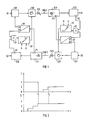
- FIG. 1 shows in the form of a block diagram how bidirectional data transmission takes place via an optical fiber arrangement consisting of optical fibers LWL1 and LWL2.
- the data to be transmitted are generated by sources Q1 and Q2 and each arrive at a transmission device which consists of a converter S11 or S21, an amplifier S12 or S22 and a transmission diode S13 or S23.
- the respective converter S11 or S21 serves to convert the respective information from the source Q1 or Q2 into an electrical signal pattern adapted for transmission on the optical fibers LWL1 and LWL2.
- the amplifiers S12 and S22 receive the signal from the respectively assigned converter S11 and S21 and amplify it Signal corresponding to the output signals from encoder devices G1 and G2, the function of which will be discussed in more detail below.
- the output signal of the transmission device S12 or S21 then reaches a light-emitting diode which, as the transmission diode S13 or S23, feeds an optical signal corresponding to the information to be transmitted into the optical waveguide LWL1 or LWL2.
- the optical waveguide LWL1 or LWL2 then leads to a receiving device, each of which consists of a light signal receiver E21 or E11 and a converter E22 or E12.
- the receiving device E21 or E22 is used to generate an electrical signal again from the light signal, the level of this signal being able to be monitored by assigned level detectors P2 or P1 (for compliance with setpoints).
- the output signal of the receiving device E21 or E22 then arrives at the respectively assigned converter U22 or U12, which recovers the information to be transmitted in each case from the electrical signal and forwards it to a respective sink of the information S1 or S2.
- the converter E22 or E12 also has an additional output A2 or A1, indicated by dashed lines, which always carries an effective signal logic "1" when a signal "received level" from the transmitter assigned to source Q1 or source Q2 low ".
- This signal results from a response of the level detector P1 or the level detector P2.
- This signal determined by the level detector P1 or level detector P2 is namely fed to a converter U1 or U2, which then, after a delay time delta t, excites the converter S11 or the converter S21 to emit the above-mentioned message.
- an OR- Link O2 or O1 activates a transmitter G2 or G1, which then, starting from a current position, increases it by "1", so that, for example, when a position 2 is present, it is switched to a position 3.
- an output signal is sent from this to the amplifier S22 or S12, which sets a transmission power there which also increases with increasing position value.
- the converter S21 is activated via the converter U2. This triggers a signal "received power too low”, transmits this via the optical fiber LWL2 to the converter E12, which detects the signal "received power too low” and accordingly the output A1 becomes active.
- the encoder G1 is then switched one level higher via the OR gate O1. As a result, the amplifier S12 is also raised by one stage and the signal then arriving in the light signal receiver E21 would then have to arrive with a higher intensity. The same applies to the other direction of transmission.
- the converter U2 or U1 is designed such that when the level detector P2 or P1 responds over longer periods of time, ie over a delay time delta T, which is greater than the delay time delta t, via the OR gate O2 or the OR gate O1 of the encoder G2 or the encoder G1 is switched up so that a feedback signal "level too low" is retransmitted with the greatest possible certainty.
- This upshifting can be carried out in stages up to the maximum output of the transmitter diodes S23 or S13.
- FIG. 2 shows how an above-mentioned initialization could take place.
- FIG 2 shows two diagrams, of which the upper diagram I may indicate the time profile of the transmission power of the transmission diode S13 and the lower diagram II the transmission power of the transmission diode S23.
- the transmitter diode S13 is first set to the maximum value in each case, "4" in the exemplary embodiment.
- the transmission power for the transmitter diode S23 is set to the lowest possible power at the same time t.
- the level detector P1 determines that the received signal is too low and accordingly requests increases until the light signal power arriving in the receiving device E11 is sufficiently large. This may be done, for example, at time t 1. This fact is indicated by diagrams I and II by a dashed line.
- the transmission power of the transmission diode S13 is reduced to the lowest possible value.
- the level detector P2 must then respond and trigger an increase in the transmission power of the transmission diode S13 via the already optimized optical fiber LWL2. This continues until, for example, at a time t2 the light signal power present at the light signal receiver E21 is sufficiently large.
Landscapes
- Physics & Mathematics (AREA)
- Electromagnetism (AREA)
- Engineering & Computer Science (AREA)
- Computer Networks & Wireless Communication (AREA)
- Signal Processing (AREA)
- Optical Communication System (AREA)
Priority Applications (3)
| Application Number | Priority Date | Filing Date | Title |
|---|---|---|---|
| EP19890123567 EP0433481B1 (fr) | 1989-12-20 | 1989-12-20 | Méthode de transmission bidirectionnelle de signaux électriques au moyen de conducteurs à fibres optiques |
| ES89123567T ES2048816T3 (es) | 1989-12-20 | 1989-12-20 | Procedimiento para la transmision bidireccional de se\ales electricas a traves de una disposicion de ondas de guia. |
| DE89123567T DE58907016D1 (de) | 1989-12-20 | 1989-12-20 | Verfahren zum bidirektionalen Übertragen elektrischer Signale über eine Lichtwellenleiteranordnung. |
Applications Claiming Priority (1)
| Application Number | Priority Date | Filing Date | Title |
|---|---|---|---|
| EP19890123567 EP0433481B1 (fr) | 1989-12-20 | 1989-12-20 | Méthode de transmission bidirectionnelle de signaux électriques au moyen de conducteurs à fibres optiques |
Publications (2)
| Publication Number | Publication Date |
|---|---|
| EP0433481A1 true EP0433481A1 (fr) | 1991-06-26 |
| EP0433481B1 EP0433481B1 (fr) | 1994-02-16 |
Family
ID=8202255
Family Applications (1)
| Application Number | Title | Priority Date | Filing Date |
|---|---|---|---|
| EP19890123567 Expired - Lifetime EP0433481B1 (fr) | 1989-12-20 | 1989-12-20 | Méthode de transmission bidirectionnelle de signaux électriques au moyen de conducteurs à fibres optiques |
Country Status (3)
| Country | Link |
|---|---|
| EP (1) | EP0433481B1 (fr) |
| DE (1) | DE58907016D1 (fr) |
| ES (1) | ES2048816T3 (fr) |
Cited By (7)
| Publication number | Priority date | Publication date | Assignee | Title |
|---|---|---|---|---|
| EP0527279A1 (fr) * | 1990-02-28 | 1993-02-17 | AT&T Corp. | Ajustement automatique de la puissance optique de sortie de plusieurs émetteurs optiques |
| DE4217899A1 (de) * | 1992-05-29 | 1993-12-02 | Phoenix Contact Gmbh & Co | Verfahren zur Systemoptimierung von Lichtwellenleiter-Übertragungsstrecken |
| WO1995008879A1 (fr) * | 1993-09-22 | 1995-03-30 | Massachussetts Institute Of Technology | Commande sensible au taux d'erreurs du courant d'excitation d'un laser |
| FR2755555A1 (fr) * | 1996-11-05 | 1998-05-07 | Debreane Ets | Interface de raccordement telephonique a haute isolation |
| WO1999008405A1 (fr) * | 1997-08-08 | 1999-02-18 | Siemens Aktiengesellschaft | Dispositif pour recevoir un signal emis et pour emettre un faisceau optique, et utilisation dudit dispositif |
| FR2771567A1 (fr) * | 1997-11-25 | 1999-05-28 | Sagem | Procede de transmission d'informations sur une liaison infrarouge et equipement pour la mise en oeuvre du procede |
| DE10140852C5 (de) * | 2001-08-21 | 2016-11-17 | Robert Bosch Gmbh | Elektronisches System mit einem Lichtwellenleiter-Netzwerk und Verfahren zum Selbsttest sowie dazugehöriges Computerprogramm |
Citations (3)
| Publication number | Priority date | Publication date | Assignee | Title |
|---|---|---|---|---|
| FR2614158A1 (fr) * | 1987-04-16 | 1988-10-21 | Setsys | Radiotelephone notamment portable |
| EP0331255A2 (fr) * | 1988-03-03 | 1989-09-06 | Philips Patentverwaltung GmbH | Système de transmission optique |
| GB2219165A (en) * | 1988-05-27 | 1989-11-29 | Stc Plc | Optical transmission systems |
-
1989
- 1989-12-20 EP EP19890123567 patent/EP0433481B1/fr not_active Expired - Lifetime
- 1989-12-20 DE DE89123567T patent/DE58907016D1/de not_active Expired - Fee Related
- 1989-12-20 ES ES89123567T patent/ES2048816T3/es not_active Expired - Lifetime
Patent Citations (3)
| Publication number | Priority date | Publication date | Assignee | Title |
|---|---|---|---|---|
| FR2614158A1 (fr) * | 1987-04-16 | 1988-10-21 | Setsys | Radiotelephone notamment portable |
| EP0331255A2 (fr) * | 1988-03-03 | 1989-09-06 | Philips Patentverwaltung GmbH | Système de transmission optique |
| GB2219165A (en) * | 1988-05-27 | 1989-11-29 | Stc Plc | Optical transmission systems |
Non-Patent Citations (2)
| Title |
|---|
| PATENT ABSTRACTS OF JAPAN, Band 10, Nr. 158 (E-409)[2214], 6. Juni 1986; & JP-A-61 12 138 (NIPPON DENKI K.K.) 20-01-1986 * |
| PATENT ABSTRACTS OF JAPAN, Band 11, Nr. 275 (E-537)[2722], 5. September 1987; & JP-A-62 76 331 (NEC CORP.) 08-04-1987 * |
Cited By (12)
| Publication number | Priority date | Publication date | Assignee | Title |
|---|---|---|---|---|
| EP0527279A1 (fr) * | 1990-02-28 | 1993-02-17 | AT&T Corp. | Ajustement automatique de la puissance optique de sortie de plusieurs émetteurs optiques |
| DE4217899A1 (de) * | 1992-05-29 | 1993-12-02 | Phoenix Contact Gmbh & Co | Verfahren zur Systemoptimierung von Lichtwellenleiter-Übertragungsstrecken |
| DE4217899C2 (de) * | 1992-05-29 | 2001-10-18 | Phoenix Contact Gmbh & Co | Verfahren zur Systemoptimierung von Lichtwellenleiter-Übertragungsstrecken |
| WO1995008879A1 (fr) * | 1993-09-22 | 1995-03-30 | Massachussetts Institute Of Technology | Commande sensible au taux d'erreurs du courant d'excitation d'un laser |
| US5623355A (en) * | 1993-09-22 | 1997-04-22 | Massachusetts Institute Of Technology | Error-rate-based laser drive control |
| FR2755555A1 (fr) * | 1996-11-05 | 1998-05-07 | Debreane Ets | Interface de raccordement telephonique a haute isolation |
| WO1999008405A1 (fr) * | 1997-08-08 | 1999-02-18 | Siemens Aktiengesellschaft | Dispositif pour recevoir un signal emis et pour emettre un faisceau optique, et utilisation dudit dispositif |
| US6259081B1 (en) | 1997-08-08 | 2001-07-10 | Siemens Aktiengesellschaft | Device for receiving a transmission signal and for transmitting an optical beam and method of using the device |
| AU741775B2 (en) * | 1997-08-08 | 2001-12-06 | Siemens Aktiengesellschaft | Device for receiving a send signal and for sending an optical beam and use thereof |
| FR2771567A1 (fr) * | 1997-11-25 | 1999-05-28 | Sagem | Procede de transmission d'informations sur une liaison infrarouge et equipement pour la mise en oeuvre du procede |
| EP0920151A1 (fr) * | 1997-11-25 | 1999-06-02 | Sagem Sa | Procédé de transmission d'informations sur une liaison infrarouge et équipement pour la mise en oeuvre du procédé |
| DE10140852C5 (de) * | 2001-08-21 | 2016-11-17 | Robert Bosch Gmbh | Elektronisches System mit einem Lichtwellenleiter-Netzwerk und Verfahren zum Selbsttest sowie dazugehöriges Computerprogramm |
Also Published As
| Publication number | Publication date |
|---|---|
| EP0433481B1 (fr) | 1994-02-16 |
| ES2048816T3 (es) | 1994-04-01 |
| DE58907016D1 (de) | 1994-03-24 |
Similar Documents
| Publication | Publication Date | Title |
|---|---|---|
| DE69117312T3 (de) | Lichtwellenleiternachrichtenübertragungsleitung mit getrennten Dienstkanälen | |
| EP0505829B1 (fr) | Système de transmission de signal optique, particulièrement système de transmission de télévision par câble, avec dispositif pour la surveillance et les canaux de service | |
| DE69017737T2 (de) | Optische Verzweigungsvorrichtung und deren Verwendung in einem optischen Netzwerk. | |
| DE3821772A1 (de) | Optischer verstaerker fuer die fehlersuche in einem optischen uebertragungssystem | |
| DE3806864A1 (de) | Optisches uebertragungssystem | |
| EP0307749B1 (fr) | Méthode pour la transmission optique de données entre deux dispositifs d'émission et de réception à séparation galvanique | |
| EP0433481B1 (fr) | Méthode de transmission bidirectionnelle de signaux électriques au moyen de conducteurs à fibres optiques | |
| DE3225773C2 (fr) | ||
| EP2052476A1 (fr) | Procédés et dispositifs conçus pour améliorer la qualité du signal | |
| DE19726940C2 (de) | Sende- und Empfangsvorrichtung zur Verstärkung der Sendesignale zwischen einer ortsfesten und einer mobilen Sendestation sowie Verfahren zum Betrieb der Kan alerkennungsvorrichtung einer Sende- und Empfangsvorrichtung | |
| WO2000013313A1 (fr) | Amplificateur optique et ligne de transmission optique | |
| DE4217899C2 (de) | Verfahren zur Systemoptimierung von Lichtwellenleiter-Übertragungsstrecken | |
| EP0973288B1 (fr) | Noeud d'interconnection pour un réseau de transmission par câble | |
| EP0973295A2 (fr) | Réseau point à multipoint | |
| DE3327489C2 (fr) | ||
| DE60122690T2 (de) | Leistungssteuerungsnetzwerkelement | |
| EP0014370B1 (fr) | Procédé de localisation de défaut sans adresse pour une ligne de transmission d'informations | |
| DE19705502A1 (de) | Funkfernsteueranlage | |
| EP3203659B1 (fr) | Unité de noeud électronique, système de transmission de données docsis et procédé de modulation de moyens de production de signaux lumineux | |
| EP0222682B1 (fr) | Système de transmission de signaux pour un dispositif de protection à comparaison | |
| DE19650088A1 (de) | System zur gerichteten Punkt-zu-Mehrpunkt Informationsübertragung | |
| EP0175994B1 (fr) | Procédé d'émission et de réception pour stations relais | |
| EP1002384A1 (fr) | Dispositif pour le transfert de signaux optiques avec fonction de circuit de remplacement | |
| EP0338274A1 (fr) | Système de transmission de données pour un arrangement sans fil signalant les risques | |
| EP0721689B1 (fr) | Procede permettant de faire fonctionner en mode de secours un appareil a telecommande centralisee |
Legal Events
| Date | Code | Title | Description |
|---|---|---|---|
| PUAI | Public reference made under article 153(3) epc to a published international application that has entered the european phase |
Free format text: ORIGINAL CODE: 0009012 |
|
| 17P | Request for examination filed |
Effective date: 19901220 |
|
| AK | Designated contracting states |
Kind code of ref document: A1 Designated state(s): AT BE CH DE ES FR GB GR LI LU SE |
|
| RBV | Designated contracting states (corrected) |
Designated state(s): CH DE ES FR GB GR LI SE |
|
| 17Q | First examination report despatched |
Effective date: 19930713 |
|
| GRAA | (expected) grant |
Free format text: ORIGINAL CODE: 0009210 |
|
| AK | Designated contracting states |
Kind code of ref document: B1 Designated state(s): CH DE ES FR GB GR LI SE |
|
| REF | Corresponds to: |
Ref document number: 58907016 Country of ref document: DE Date of ref document: 19940324 |
|
| REG | Reference to a national code |
Ref country code: ES Ref legal event code: FG2A Ref document number: 2048816 Country of ref document: ES Kind code of ref document: T3 |
|
| ET | Fr: translation filed | ||
| GBT | Gb: translation of ep patent filed (gb section 77(6)(a)/1977) |
Effective date: 19940520 |
|
| REG | Reference to a national code |
Ref country code: GR Ref legal event code: FG4A Free format text: 3011649 |
|
| PLBE | No opposition filed within time limit |
Free format text: ORIGINAL CODE: 0009261 |
|
| STAA | Information on the status of an ep patent application or granted ep patent |
Free format text: STATUS: NO OPPOSITION FILED WITHIN TIME LIMIT |
|
| EAL | Se: european patent in force in sweden |
Ref document number: 89123567.3 |
|
| 26N | No opposition filed | ||
| PGFP | Annual fee paid to national office [announced via postgrant information from national office to epo] |
Ref country code: GR Payment date: 19981218 Year of fee payment: 10 |
|
| PGFP | Annual fee paid to national office [announced via postgrant information from national office to epo] |
Ref country code: SE Payment date: 19981222 Year of fee payment: 10 |
|
| PG25 | Lapsed in a contracting state [announced via postgrant information from national office to epo] |
Ref country code: SE Free format text: LAPSE BECAUSE OF NON-PAYMENT OF DUE FEES Effective date: 19991221 |
|
| PG25 | Lapsed in a contracting state [announced via postgrant information from national office to epo] |
Ref country code: GR Free format text: LAPSE BECAUSE OF NON-PAYMENT OF DUE FEES Effective date: 19991231 |
|
| EUG | Se: european patent has lapsed |
Ref document number: 89123567.3 |
|
| REG | Reference to a national code |
Ref country code: GB Ref legal event code: IF02 |
|
| PGFP | Annual fee paid to national office [announced via postgrant information from national office to epo] |
Ref country code: DE Payment date: 20020218 Year of fee payment: 13 |
|
| PGFP | Annual fee paid to national office [announced via postgrant information from national office to epo] |
Ref country code: CH Payment date: 20020311 Year of fee payment: 13 |
|
| PGFP | Annual fee paid to national office [announced via postgrant information from national office to epo] |
Ref country code: GB Payment date: 20021205 Year of fee payment: 14 |
|
| PGFP | Annual fee paid to national office [announced via postgrant information from national office to epo] |
Ref country code: FR Payment date: 20021220 Year of fee payment: 14 Ref country code: ES Payment date: 20021220 Year of fee payment: 14 |
|
| PG25 | Lapsed in a contracting state [announced via postgrant information from national office to epo] |
Ref country code: LI Free format text: LAPSE BECAUSE OF NON-PAYMENT OF DUE FEES Effective date: 20021231 Ref country code: CH Free format text: LAPSE BECAUSE OF NON-PAYMENT OF DUE FEES Effective date: 20021231 |
|
| PG25 | Lapsed in a contracting state [announced via postgrant information from national office to epo] |
Ref country code: DE Free format text: LAPSE BECAUSE OF NON-PAYMENT OF DUE FEES Effective date: 20030701 |
|
| REG | Reference to a national code |
Ref country code: CH Ref legal event code: PL |
|
| PG25 | Lapsed in a contracting state [announced via postgrant information from national office to epo] |
Ref country code: GB Free format text: LAPSE BECAUSE OF NON-PAYMENT OF DUE FEES Effective date: 20031220 |
|
| PG25 | Lapsed in a contracting state [announced via postgrant information from national office to epo] |
Ref country code: ES Free format text: LAPSE BECAUSE OF NON-PAYMENT OF DUE FEES Effective date: 20031222 |
|
| GBPC | Gb: european patent ceased through non-payment of renewal fee |
Effective date: 20031220 |
|
| PG25 | Lapsed in a contracting state [announced via postgrant information from national office to epo] |
Ref country code: FR Free format text: LAPSE BECAUSE OF NON-PAYMENT OF DUE FEES Effective date: 20040831 |
|
| REG | Reference to a national code |
Ref country code: FR Ref legal event code: ST |
|
| REG | Reference to a national code |
Ref country code: ES Ref legal event code: FD2A Effective date: 20031222 |