EP0433497A1 - Matrixdruckkopf, insbesondere serieller Matrixnadeldruckkopf - Google Patents
Matrixdruckkopf, insbesondere serieller Matrixnadeldruckkopf Download PDFInfo
- Publication number
- EP0433497A1 EP0433497A1 EP89250118A EP89250118A EP0433497A1 EP 0433497 A1 EP0433497 A1 EP 0433497A1 EP 89250118 A EP89250118 A EP 89250118A EP 89250118 A EP89250118 A EP 89250118A EP 0433497 A1 EP0433497 A1 EP 0433497A1
- Authority
- EP
- European Patent Office
- Prior art keywords
- armature
- magnetic yoke
- pin
- needle
- matrix
- Prior art date
- Legal status (The legal status is an assumption and is not a legal conclusion. Google has not performed a legal analysis and makes no representation as to the accuracy of the status listed.)
- Granted
Links
- 239000011159 matrix material Substances 0.000 title claims abstract description 28
- 238000004519 manufacturing process Methods 0.000 claims abstract description 11
- 238000007639 printing Methods 0.000 claims description 12
- 238000004080 punching Methods 0.000 claims description 9
- 241000446313 Lamella Species 0.000 claims description 6
- 239000000314 lubricant Substances 0.000 claims description 4
- 238000000034 method Methods 0.000 claims description 3
- 238000012856 packing Methods 0.000 claims description 3
- 230000000284 resting effect Effects 0.000 claims description 2
- 230000004907 flux Effects 0.000 description 4
- 241000252185 Cobitidae Species 0.000 description 2
- 238000005516 engineering process Methods 0.000 description 2
- 230000002349 favourable effect Effects 0.000 description 2
- 238000003475 lamination Methods 0.000 description 2
- OKTJSMMVPCPJKN-UHFFFAOYSA-N Carbon Chemical compound [C] OKTJSMMVPCPJKN-UHFFFAOYSA-N 0.000 description 1
- 241001295925 Gegenes Species 0.000 description 1
- 238000010276 construction Methods 0.000 description 1
- 238000001816 cooling Methods 0.000 description 1
- 238000009826 distribution Methods 0.000 description 1
- 229910002804 graphite Inorganic materials 0.000 description 1
- 239000010439 graphite Substances 0.000 description 1
- 239000003921 oil Substances 0.000 description 1
- 238000005245 sintering Methods 0.000 description 1
- 238000003860 storage Methods 0.000 description 1
- 238000003466 welding Methods 0.000 description 1
Images

Classifications
-
- B—PERFORMING OPERATIONS; TRANSPORTING
- B41—PRINTING; LINING MACHINES; TYPEWRITERS; STAMPS
- B41J—TYPEWRITERS; SELECTIVE PRINTING MECHANISMS, i.e. MECHANISMS PRINTING OTHERWISE THAN FROM A FORME; CORRECTION OF TYPOGRAPHICAL ERRORS
- B41J2/00—Typewriters or selective printing mechanisms characterised by the printing or marking process for which they are designed
- B41J2/22—Typewriters or selective printing mechanisms characterised by the printing or marking process for which they are designed characterised by selective application of impact or pressure on a printing material or impression-transfer material
- B41J2/23—Typewriters or selective printing mechanisms characterised by the printing or marking process for which they are designed characterised by selective application of impact or pressure on a printing material or impression-transfer material using print wires
- B41J2/27—Actuators for print wires
- B41J2/275—Actuators for print wires of clapper type
Definitions
- the invention relates to a matrix print head, in particular a serial matrix needle print head, which is arranged at a needle stroke distance from a print abutment, on which a recording medium lies, and an ink ribbon guided in front of it, has a print needle guide housing and a print needle drive housing, with each print needle in the print needle drive housing being assigned a magnetic drive, Consisting of a magnetic yoke, on one of which a magnetic yoke leg is arranged, and an armature that can be pivoted by means of a pin bearing and rests in a rearward position against a stop by means of a spring, a working air gap being formed between the armature and a front face of the magnetic yoke leg .
- the invention further relates to a method for producing a magnetic drive for matrix printheads, in particular for serial matrix needle printheads, each of which consists of a magnetic yoke, on the one yoke leg of which an electromagnetic coil is arranged, and also consists of an armature which can be pivoted by means of a pin bearing.
- the anchors can be adjusted in rapid succession against the pole faces of the magnetic yokes and back to a rest position in order to generate a high number of pressure points at the ends of the printing needles.
- the frequency of such matrix printheads has now reached 2000 Hz and is to be increased further to approximately 3000 Hz and more per printing element.
- such matrix print heads are used by printers for high data output from computers.
- a matrix print head is known (US Pat. No. 4,242,004) which has the features of the type mentioned in the introduction. Deviating from this, it is known to attach the pressure needle to a spring arm, which is followed by a special kinematics. However, this design requires a very wide anchor and is therefore not suitable for the design of an 18- or 24-pin printhead. In addition, the known printhead is disadvantageous for production with the corresponding accuracy.
- the object of the present invention is to make the known printhead suitable for series production and to achieve the required accuracy and the correspondingly high frequency.
- a recess is arranged in the middle of the magnet yoke thickness, in which a central arm of the armature is pivoted by means of the pin, the pin axis running laterally to the area of the magnet yoke leg center.
- the main advantage of such a pin bearing is the position of the pin outside or at the edge of the main magnetic flux, whereby less energy losses occur compared to it if the pin were arranged in the middle.
- a pin arrangement in the radially inner magnetic yoke leg and there in the vicinity of the radially inner edge is advantageous.
- Such a printhead can advantageously be manufactured in series.
- the required accuracy can be achieved both in the manufacture of the armature and in the manufacture of the magnetic yoke and in its connection or alignment with one another.
- the speed of the magnet system is achieved by means of a precisely determinable armature stroke path, because the position of the pin axis allows the armature to be zero in its pressure position on the end face of the magnet yoke leg in question.
- An improvement of the invention consists in that at least one guide sword is provided on the side of the armature opposite a magnet yoke end face which engages in the recess of the magnet yoke in which the pin axis runs.
- both the armature and the magnetic yoke consist of stacked lamellae, at least one central recess with the thickness of a lamella forming the armature arm being provided and that the armature over the two magnetic yoke legs with an approximately trapezoidal shape Cross section is formed.
- lubricants are stored between the individual lamellae. This prevents wear and also prevents sticking between the armature and the magnet yoke faces.
- the pen is lubricated on its circumference. This is particularly advantageous in the area of storage in the yoke. The conveyance of the lubricant is favored by magnetostriction of the soft magnetic parts (armature, yoke).
- a magnetic yoke with an armature or armature arm and a pin form a unit in the assembled state of the electromagnetic coil.
- the individual parts can be manufactured with the desired accuracy and the assembly unit can thus easily be used for a serial printhead or alternatively for a parallel printhead (line module). The decision about this can therefore be based on the order situation resultant numbers of matrix print heads of the serial type or the line printer type can be made.
- This procedure ensures a safe and very precise position of the armature in relation to the magnetic yoke.
- the magnetic properties of the matrix printhead are significantly improved. Above all, this also optimally shapes the air gap setting in the printing position.
- the matrix print head shown in FIG. 1 represents a serial matrix needle print head which is arranged with a needle stroke distance 1 opposite a print abutment 2.
- a recording medium 3 On the pressure abutment 2, a recording medium 3 is fully seated.
- the printing needles 4 form one or more vertical needle gaps of, for example, 2 ⁇ 9 or 2 in the mouthpiece 5 x 12 printing needles.
- the printing needles 4 are held and guided in their entirety in a printing needle guide housing 7 with support planes 8.
- the printing needles 4 extend into a rear printing needle drive housing 9, which is closed by a cover 10.
- the cover 10 has cooling fins 11 for the dissipation of heat by Magnet drives 12 arises.
- a magnetic drive 12 is assigned to each print needle 4 in the print needle drive housing 9.
- Each magnetic drive 12 consists of a magnetic yoke 13.
- Each magnetic yoke 13 consists of two magnetic yoke legs 13a and 13b and a magnetic yoke base 13c.
- An electromagnetic coil 14 is pushed onto a magnetic yoke leg 13a, 13b.
- Each magnet drive 12 also includes an armature 15, which can be pivoted by means of a pin bearing 16 and bears in a rearward position against a stop 18 by means of a spring 17, a working air gap 20 to be described in more detail between the armature 15 and a magnet yoke leg end face 19 is formed.
- a recess 22 in the magnetic yoke 13, extending in the longitudinal direction of the armature 15, is arranged in the center of the magnetic yoke thickness 21, which extends partly horizontally, partly obliquely (FIG. 1) or only obliquely (FIG. 2a).
- a central arm 15a of the armature 15 engages in the recess 22, which guides the armature 15 very precisely and thereby avoids lateral transverse movements which would be undesirable.
- the central arm 15a is rotatably supported by means of a bearing pin 23 of the pin bearing 16 and the pin axis 23a extends laterally in the area of the center of the magnetic yoke leg 24.
- a guide sword 15b is attached to the armature arm 15a or to a trapezoidal cross section 28 for precise lateral guidance.
- This area lies more on the magnetic yoke side surface 25 and can e.g. as shown in Fig. 2, coincide with the plane of the magnet yoke side surface 25.
- the pin axis 23a is in no way to be arranged in the middle of one of the magnetic yoke legs 13a or 13b.
- the recess 22 runs exclusively at an angle and part of the armature arm 15a, here designated 15b, projects into the recess 22 in.
- the horizontal pin axis 23a extends laterally to the area of the center of the magnetic yoke leg 24, this time in the area of the radially outer side of the magnetic yoke leg 25.
- the pin bearing 16 according to FIG. 2 forms an eye 26 which can be produced by punching lamellae as described below.
- Both the armature 15 and the magnetic yoke 13 are formed from laminations 27 stacked one on top of the other, with at least one central recess 22 having the thickness 28a of a laminate 27 (or also of several laminations) being present and the one laminate 27 (or more) being the armature arm 15a of the anchor.
- the armature 15 closes exactly over the two magnetic yoke legs 13a, 13b and is provided with an approximately trapezoidal cross section 28.
- Both the armature 15 and the magnetic yoke 13 can be held together by rivets, spot welding or pressure pin connections 29.
- the armature 15 and the magnetic yoke 13, on the other hand can also be produced in one piece with the illustrated outer shape in sintering tools.
- lubricant is also stored between the individual lamellas 27, which can consist of graphite or heat-resistant oils of a natural or synthetic nature.
- the assembly unit according to FIG. 3 is designed differently. Although the greatest width of the arm 15a is also in the region of the pin bearing 16 here, the course of the outline of the arm 15a is continuous on the "underside", but discontinuous on the "top”. The discontinuous course 37 results in a higher vibration stiffness depending on the application.
Landscapes
- Impact Printers (AREA)
- Facsimile Heads (AREA)
- Particle Formation And Scattering Control In Inkjet Printers (AREA)
Abstract
Description
- Die Erfindung betrifft einen Matrixdruckkopf, insbesondere einen seriellen Matrixnadeldruckkopf, der mit Nadelhubabstand gegenüber einem Druckwiderlager, auf dem ein Aufzeichnungsträger liegt, und einem vor diesem geführten Farbband angeordnet ist, ein Drucknadelführungsgehäuse und ein Drucknadelantriebsgehäuse aufweist, wobei jeder Drucknadel im Drucknadelantriebsgehäuse ein Magnetantrieb zugeordnet ist, bestehend aus einem Magnetjoch, auf dessen einem Magnetjochschenkel eine Elektromagnetspule angeordnet ist, ferner aus einem Anker, der mittels einer Stiftlagerung schwenkbar ist und mittels einer Feder in einer rückwärtigen Position gegen einen Anschlag anliegt, wobei zwischen Anker und einer Magnetjochschenkel-Stirnseite ein Arbeitsluftspalt gebildet ist.
- Die Erfindung betrifft ferner ein Verfahren zum Herstellen eines Magnetantriebs für Matrixdruckköpfe, insbesondere für serielle Matrixnadeldruckköpfe, der jeweils aus einem Magnetjoch, auf dessen einem Magnetjochschenkel eine Elektromagnetspule angeordnet ist, ferner aus einem Anker besteht, der mittels einer Stiftlagerung schwenkbar ist.
- Bei derartigen Matrixdruckköpfen sind die Anker in schneller Folge gegen die Polflächen der Magnetjoche und zurück in eine Ruhestellung anstellbar, um eine hohe Zahl von Druckpunkten an den Enden der Drucknadeln zu erzeugen. Die Frequenz derartiger Matrixdruckköpfe hat inzwischen 2000 Hz erreicht und soll weiter gesteigert werden auf ca. 3000 Hz und mehr pro Druckelement. Entsprechend der hohen Frequenzen dienen derartige Matrixdruckköpfe Druckern für einen hohen Datenausstoß von Computern.
- Es ist ein Matrixdruckkopf bekannt (US-4,242,004), der die Merkmale der einleitend genannten Gattung aufweist. Abweichend davon ist es bekannt, die Drucknadel an einem Federarm zu befestigen, womit eine besondere Kinematik verfolgt wird. Diese Bauweise erfordert jedoch einen sehr breiten Anker und eignet sich daher nicht für die Konzeption eines 18- oder 24-Nadeldruckkopfes. Außerdem ist der bekannte Druckkopf für die Herstellung bei entsprechender Genauigkeit unvorteilhaft.
- Die Aufgabe der vorliegenden Erfindung besteht darin, den bekannten Druckkopf für eine Serienfertigung geeignet zu gestalten und hierbei die geforderte Genauigkeit und die entsprechend hohe Frequenz zu erzielen.
- Die gestellte Aufgabe wird für die eingangs erwähnte Gattung erfindungsgemäß dadurch gelöst, daß mittig zur Magnetjochdicke eine Ausnehmung angeordnet ist, in der ein mittiger Arm des Ankers mittels des Stiftes schwenkgelagert ist, wobei die Stiftachse seitlich zum Bereich der Magnetjochschenkelmitte verläuft. Der wesentliche Vorteil einer solchen Stiftlagerung ist die Lage des Stiftes außerhalb bzw. am Rand des Hauptmagnetflusses, wodurch geringere Energieverluste demgegenüber entstehen, als wenn der Stift mittig angeordnet wäre. Vorteilhaft ist z.B. eine Stiftanordnung im radial inneren Magnetjochschenkel und dort in der Nähe der radial inneren Kante. Ein solcher Druckkopf kann serienmäßig vorteilhaft hergestellt werden. Die geforderte Genauigkeit kann sowohl bei der Herstellung des Ankers als auch bei der Herstellung des Magnetjochs und bei dessen Verbindung bzw. Ausrichtung zueinander erzielt werden. Die Schnelligkeit des Magnetsystems wird durch einen genau bestimmbaren Ankerhubweg erreicht, weil die Lage der Stiftachse eine Null-Anlage des Ankers in seiner Druckposition an der Stirnseite des betreffenden Magnetjochschenkels gestattet.
- Eine Verbesserung der Erfindung besteht darin, daß an der einer Magnetjochstirnseite gegenüberliegenden Seite des Ankers zumindest ein Führungsschwert vorgesehen ist, das in die Ausnehmung des Magnetjochs eingreift, in dem die Stiftachse verläuft.
- Eine besonders vorteilhafte Ausgestaltung wird dadurch erzielt, daß sowohl der Anker als auch das Magnetjoch aus aufeinandergeschichteten Lamellen bestehen, wobei zumindest eine mittlere Ausnehmung mit der Dicke einer Lamelle, die den Ankerarm bildet, vorgesehen ist und daß der Anker über den beiden Magnetjochschenkeln mit etwa trapezförmigem Querschnitt ausgebildet ist. Diese Lösung ist fertigungstechnisch leicht zu beherrschen und führt außerdem zu einer günstigen Masse-Verteilung zwischen Anker und Ankerarm und damit zu einem optimalen magnetischen Fluß im Magnetjoch bzw. im Anker. Nicht notwendig ist hierbei ein Magnetfluß im Ankerarm.
- Eine weitere Verbesserung besteht darin, daß zwischen den einzelnen Lamellen Schmierstoffe eingelagert sind. Dadurch wird ein Verschleiß und außerdem ein Haften zwischen Anker und den Magnetjochstirnflächen verhindert. Außerdem wird auch noch der Stift an seinem Umfang geschmiert. Dies ist insbesondere im Bereich der Lagerung im Joch vorteilhaft. Die Förderung des Schmierstoffs wird durch Magnetostriktion der weichmagnetischen Teile (Anker, Joch) begünstigt.
- Fertigungstechnisch ist es außerdem günstig, daß ein Magnetjoch mit einem Anker bzw. einem Ankerarm und ein Stift in montiertem Zustand der Elektromagnetspule eine Einheit bilden. Die Einzelteile können mit gewünschter Genauigkeit hergestellt werden und die Baugruppen-Einheit läßt sich dadurch leicht für einen seriellen Druckkopf oder alternativ für einen parallelen Druckkopf (Zeilenbaustein) verwenden. Die Entscheidung hierüber kann daher aufgrund der sich nach der Auftragslage ergebenden Stückzahlen von Matrixdruckköpfen der seriellen Bauart oder der Zeilendruckerbauart getroffen werden.
- Weiterhin vorteilhaft ist ein Verfahren zum Herstellen eines Magnetantriebs für Matrixdruckköpfe, insbesondere für serielle Matrixnadeldruckköpfe der eingangs erwähnten Bauart. Hierzu werden folgende Verfahrensschritte nacheinander ausgeführt:
- 1. Stanzen der Magnetjoch-Lamellen mit Außenform und Vorstanzen eines Loches für die Stiftlagerung;
- 2. Paketieren der so gestanzten Magnetjoch-Lamellen zwecks Herstellung eines Stiftloches mit Rohdurchmesser;
- 3. Kalibrieren des rohen Stiftloches;
- 4. Anker ohne Nadel bzw. Anker mit Nadel derart einsetzen, daß eine mittlere Ankerlamelle in eine mittige Ausnehmung zwischen zwei Lamellenpaketen eingreift;
- 5. hierbei den Anker an den Außenkanten des Magnetjoches ausrichten;
- 6. Einsetzen eines Lochstempels in das kalibrierte Stiftloch, Lochen der Ankerlamelle, wobei der Anker luftspaltfrei auf der Magnetjochschenkel-Stirnseite aufliegt und wobei der Lochstempel gleichzeitig als Lagerstift verbleibt.
- Dieses Verfahren gewährleistet eine sichere und sehr genaue Lage des Ankers gegenüber dem Magnetjoch. Außerdem werden die magnetischen Eigenschaften des Matrixdruckkopfes erheblich verbessert. Vor allen Dingen wird dadurch auch die Luftspalteinstellung in der Druckposition optimal gestaltet.
- Ausführungsbeispiele der Erfindung sind in der Zeichnung dargestellt und werden im folgenden näher beschrieben. Es zeigen:
- Fig. 1 einen Längsschnitt durch einen seriellen Matrixnadeldruckkopf,
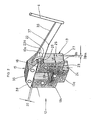
- Fig. 2 eine Baueinheit, bestehend aus Magnetjoch, Anker und Stiftlagerung mit einer ersten Ausführungsform des Ankerarms in perspektivischer Darstellung,
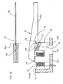
- Fig. 2a eine Seitenansicht mit Teilschnitt der Baueinheit,
- Fig. 2b eine Ansicht von unten gegen den Anker,
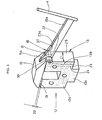
- Fig. 3 die Baueinheit wie Fig. 2 mit einer zweiten Ausführungsform des Ankerarms, ebenfalls in perspektivischer Darstellung und
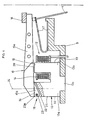
- Fig. 4 die Anwendung des Matrixnadeldruckkopfes für einen seriellen oder zeilenweise schreibenden Matrixdruckkopf in einer Alternativ-Ausführungsform der Stiftlagerung.
- Der in Fig. 1 dargestellte Matrixdruckkopf stellt einen seriellen Matrixnadeldruckkopf dar, der mit einem Nadelhubabstand 1 gegenüber einem Druckwiderlager 2 angeordnet ist. Auf dem Druckwiderlager 2 liegt ein Aufzeichnungsträger 3 satt auf. Vor dem Aufzeichnungsträger 3, d.h. zwischen den Enden von Drucknadeln 4, die in einem Mundstück 5 geführt sind, befindet sich ein kontinuierlich oder diskontinuierlich bewegtes Farbband 6. Die Drucknadeln 4 bilden im Mundstück 5 eine oder mehrere senkrechte Nadelspalten von z.B. 2 x 9 oder 2 x 12 Drucknadeln. Die Drucknadeln 4 sind in ihrer Gesamtheit in einem Drucknadelführungsgehäuse 7 mit Stützebenen 8 gehalten und geführt. Die Drucknadeln 4 verlaufen bis in ein rückwärtiges Drucknadelantriebsgehäuse 9, das durch einen Deckel 10 verschlossen ist. Der Deckel 10 weist Kühlrippen 11 zur Abfuhr von Wärme auf, die durch Magnetantriebe 12 entsteht.
- Jeder Drucknadel 4 ist im Drucknadelantriebsgehäuse 9 ein Magnetantrieb 12 zugeordnet. Jeder Magnetantrieb 12 besteht jeweils aus einem Magnetjoch 13. Jedes Magnetjoch 13 besteht aus zwei Magnetjochschenkeln 13a und 13b sowie aus einem Magnetjochfuß 13c. Auf einem Magnetjochschenkel 13a, 13b ist eine Elektromagnetspule 14 aufgeschoben. Zu jedem Magnetantrieb 12 gehört außerdem ein Anker 15, der mittels einer Stiftlagerung 16 schwenkbar ist und mittels einer Feder 17 in einer rückwärtigen Position gegen einen Anschlag 18 anliegt, wobei zwischen dem Anker 15 und einer Magnetjochschenkel- Stirnseite 19 ein noch näher zu beschreibender Arbeitsluftspalt 20 gebildet ist.
- Mittig zur Magnetjochdicke 21 ist eine Ausnehmung 22 im Magnetjoch 13, sich in Längsrichtung des Ankers 15 erstreckend, angeordnet, die teils horizontal, teils schräg verläuft (Fig. 1) oder nur schräg (Fig. 2a). In die Ausnehmung 22 greift ein mittiger Arm 15a des Ankers 15 ein, der den Anker 15 sehr genau führt und dadurch seitliche Querbewegungen, die unerwünscht wären, vermeidet. Der mittige Arm 15a ist mittels eines Lagerstiftes 23 der Stiftlagerung 16 drehgelagert und die Stiftachse 23a verläuft seitlich im Bereich der Magnetjochschenkelmitte 24. Für die genaue seitliche Führung ist am Ankerarm 15a bzw. an einem trapezförmigen Querschnitt 28 ein Führungsschwert 15b angebracht.
- Dieser Bereich liegt mehr an der Magnetjochschenkel-Seitenfläche 25 und kann z.B. wie in Fig. 2 gezeichnet ist, mit der Ebene der Magnetjochschenkel-Seitenfläche 25 zusammenfallen. Jedenfalls ist aus noch näher zu beschreibenden Gründen die Stiftachse 23a keinesfalls in der Mitte eines der Magnetjochschenkel 13a oder 13b anzuordnen.
- Die Ausnehmung 22 verläuft gemäß Fig. 4 ausschließlich schräg und ein Teil des Ankerarms 15a, hier mit 15b bezeichnet, ragt in die Ausnehmung 22 hinein. Auch hier verläuft die horizontale Stiftachse 23a seitlich zum Bereich der Magnetjochschenkelmitte 24, und zwar diesmal im Bereich der radial äußeren Magnetjochschenkel-Seitenfläche 25.
- Die Stiftlagerung 16 gemäß Fig. 2 bildet ein Auge 26, das wie nachstehend beschrieben durch Stanzen von Lamellen hergestellt werden kann.
- Sowohl der Anker 15 als auch das Magnetjoch 13 sind aus aufeinandergeschichteten Lamellen 27 gebildet, wobei zumindest eine mittlere Ausnehmung 22 mit der Dicke 28a einer Lamelle 27 (oder auch von mehreren Lamellen) vorhanden ist und die eine Lamelle 27 (oder mehrere) den Ankerarm 15a des Ankers darstellt. Der Anker 15 schließt exakt über den beiden Magnetjochschenkeln 13a, 13b ab und ist mit etwa trapezförmigem Querschnitt 28 versehen. Sowohl der Anker 15 als auch das Magnetjoch 13 können durch Nieten, Punktschweißung oder Preßstiftverbindungen 29 zusammengehalten werden. Der Anker 15 und das Magnetjoch 13 können andererseits auch in Sinterwerkzeugen einstückig mit der dargestellten äußeren Form hergestellt werden. Bei Lamellenbauweise ist zwischen den einzelnen Lamellen 27 noch Schmierstoff eingelagert, der z.B. aus Graphit oder wärmebeständigen Ölen natürlicher oder synthetischer Art bestehen kann.
- Wie in den Fig. 2 und 3 bzw. 4 gezeigt ist, bilden jeweils ein Magnetjoch 13 mit einem Anker 15 bzw. einem Ankerarm 15a und ein Stift 23 im montierten Zustand der Elektromagnetspule (in den Fig. 2 und 3 ist diese nicht gezeichnet) eine Baueinheit.
- Der Magnetantrieb 12, bestehend aus jeweils einem Magnetjoch 13, auf dessen einem Magnetjochschenkl 13a bzw. 13b eine Elektromagnetspule 14 aufsteckbar ist, ferner aus einem Anker 15 bestehend, weist eine Stiftlagerung 16 auf. Die Genauigkeit der Lage, der Abmessungen und der Grundanordnung der Teile sowie der gewünschte effektive Magnetfluß werden durch die nachfolgenden Schritte bei der Fertigung bzw. Montage erzielt:
- 1. Stanzen der Magnetjoch-Lamellen 27 mit Außenform und Vorstanzen eines Loches für die Stiftlagerung 16;
- 2. Paketieren der so gestanzten Magnetjoch-Lamellen 27, zwecks Herstellung eines Stiftloches mit innerem Rohdurchmesser;
- 3. Kalibrieren des rohen Stiftloches auf ein Vormaß;
- 4. der Anker 15 ohne die Drucknadel 4 bzw. der Anker 15 mit der Drucknadel 4 wird derart eingesetzt, daß eine mittlere Ankerlamelle 35 in eine mittige Ausnehmung 22 zwischen zwei seitlichen Lamellen-Paketen 30 und 31 eingreift;
- 5. Hierbei wird der Anker 15 an den Außenkanten 32 und 33 des Magnetjoches 13 ausgerichtet;
- 6. danach wird ein Lochstempel 34 in das kalibrierte Stiftloch eingesetzt, dadurch wird die Ankerlamelle 35 fertiggelocht; hierbei muß der Anker 15 luftspaltfrei auf der Magnetjochschenkel-Stirnseite 19 aufliegen; außerdem dient der Lochstempel 34 gleichzeitig als Lagerstift 23.
- Anders ist die Baugruppen-Einheit gemäß Fig. 3 gestaltet. Zwar liegt die größte Breite des Ankerarms 15a auch hier im Bereich der Stiftlagerung 16, jedoch ist der Verlauf des Umrisses am Ankerarm 15a an der "Unterseite" stetig, dagegen an der "Oberseite" unstetig. Der unstetige Verlauf 37 ergibt je nach Anwendung eine höhere Schwingungssteifigkeit.
Claims (6)
dadurch gekennzeichnet,
daß mittig zur Magnetjochdicke (21) eine Ausnehmung (22) angeordnet ist, in der ein mittiger Arm (15a) des Ankers (15) mittels des Stiftes (23) schwenkgelagert ist, wobei die Stiftachse (23a) seitlich zum Bereich der Magnetjochschenkelmitte (24) verläuft, d.h. im Bereich der Magnetjochseitenfläche (25) des Magnetjochschenkels (13a,13b).
dadurch gekennzeichnet,
daß an der einer Magnetjochstirnseite (19) gegenüberliegenden Seite des Ankers (15) zumindest ein Führungsschwert (15b) vorgesehen ist, das in die Ausnehmung (22) des Magnetjochs (13) eingreift, in dem die Stiftachse (23a) verläuft.
dadurch gekennzeichnet,
daß sowohl der Anker (15) als auch das Magnetjoch (13) aus aufeinandergeschichteten Lamellen (27) bestehen, wobei zumindest eine mittlere Ausnehmung (22) mit der Dicke (28) einer Lamelle (27), die den Ankerarm (15a) bildet, vorgesehen ist und daß der Anker (15) über den beiden Magnetjochschenkeln (13a,13b) mit etwa trapezförmigem Querschnitt (28) ausgebildet ist.
dadurch gekennzeichnet,
daß zwischen den einzelnen Lamellen (27) Schmierstoffe eingelagert sind.
dadurch gekennzeichnet,
daß ein Magnetjoch (13) mit einem Anker (15) bzw. einem Ankerarm (15a) und ein Stift (23) in montiertem Zustand der Elektromagnetspule (14) eine Einheit bilden.
dadurch gekennzeichnet,
daß folgende Verfahrensschritte nacheinander ausgeführt werden:
Priority Applications (5)
| Application Number | Priority Date | Filing Date | Title |
|---|---|---|---|
| DE89250118T DE58907361D1 (de) | 1989-12-18 | 1989-12-18 | Matrixdruckkopf, insbesondere serieller Matrixnadeldruckkopf. |
| AT89250118T ATE103538T1 (de) | 1989-12-18 | 1989-12-18 | Matrixdruckkopf, insbesondere serieller matrixnadeldruckkopf. |
| EP89250118A EP0433497B1 (de) | 1989-12-18 | 1989-12-18 | Matrixdruckkopf, insbesondere serieller Matrixnadeldruckkopf |
| JP2337026A JPH03190755A (ja) | 1989-12-18 | 1990-11-30 | ドットマトリクスプリンタヘッド |
| US07/628,715 US5290112A (en) | 1989-12-18 | 1990-12-17 | Matrix print head, in particular serial matrix pin print head |
Applications Claiming Priority (1)
| Application Number | Priority Date | Filing Date | Title |
|---|---|---|---|
| EP89250118A EP0433497B1 (de) | 1989-12-18 | 1989-12-18 | Matrixdruckkopf, insbesondere serieller Matrixnadeldruckkopf |
Publications (2)
| Publication Number | Publication Date |
|---|---|
| EP0433497A1 true EP0433497A1 (de) | 1991-06-26 |
| EP0433497B1 EP0433497B1 (de) | 1994-03-30 |
Family
ID=8202550
Family Applications (1)
| Application Number | Title | Priority Date | Filing Date |
|---|---|---|---|
| EP89250118A Expired - Lifetime EP0433497B1 (de) | 1989-12-18 | 1989-12-18 | Matrixdruckkopf, insbesondere serieller Matrixnadeldruckkopf |
Country Status (5)
| Country | Link |
|---|---|
| US (1) | US5290112A (de) |
| EP (1) | EP0433497B1 (de) |
| JP (1) | JPH03190755A (de) |
| AT (1) | ATE103538T1 (de) |
| DE (1) | DE58907361D1 (de) |
Families Citing this family (18)
| Publication number | Priority date | Publication date | Assignee | Title |
|---|---|---|---|---|
| JP2567150Y2 (ja) * | 1991-01-31 | 1998-03-30 | シチズン時計株式会社 | 印字ヘッド |
| JP4592159B2 (ja) * | 2000-06-30 | 2010-12-01 | 三菱重工業株式会社 | 電磁クラッチおよび該電磁クラッチを備えた圧縮機 |
| US6682233B2 (en) * | 2002-03-18 | 2004-01-27 | Toshiba Tec Kabushika Kaisha | Supporting structure of an armature of a wire dot printer head |
| US7314323B2 (en) * | 2003-09-03 | 2008-01-01 | Toshiba Tec Kabushiki Kaisha | Wire dot printer head and wire dot printer |
| US7008126B2 (en) * | 2003-09-04 | 2006-03-07 | Toshiba Tec Kabushiki Kaisha | Wire dot printer head and wire dot printer |
| US20050076866A1 (en) * | 2003-10-14 | 2005-04-14 | Hopper Mark L. | Electromechanical valve actuator |
| US7172351B2 (en) * | 2004-01-26 | 2007-02-06 | Toshiba Tec Kabushiki Kaisha | Method for manufacturing an armature |
| JP2005254663A (ja) * | 2004-03-12 | 2005-09-22 | Toshiba Tec Corp | ワイヤドットプリンタヘッド及びワイヤドットプリンタ |
| JP2005254665A (ja) * | 2004-03-12 | 2005-09-22 | Toshiba Tec Corp | アーマチュア、ワイヤドットプリンタヘッド及びワイヤドットプリンタ |
| JP4562406B2 (ja) * | 2004-03-12 | 2010-10-13 | 東芝テック株式会社 | ワイヤドットプリンタヘッド及びワイヤドットプリンタ |
| JP4515121B2 (ja) * | 2004-03-15 | 2010-07-28 | 東芝テック株式会社 | ワイヤドットプリンタヘッド及びワイヤドットプリンタ |
| JP2005254732A (ja) * | 2004-03-15 | 2005-09-22 | Toshiba Tec Corp | ワイヤドットプリンタヘッド及びワイヤドットプリンタ |
| JP4473021B2 (ja) * | 2004-03-22 | 2010-06-02 | 東芝テック株式会社 | 窒化層形成方法、磁気回路形成部材、アーマチュア、ワイヤドットプリンタヘッド及びワイヤドットプリンタ |
| JP2005262803A (ja) * | 2004-03-22 | 2005-09-29 | Toshiba Tec Corp | ヨークの製造方法、ヨーク、ワイヤドットプリンタヘッド及びワイヤドットプリンタ |
| JP4628689B2 (ja) * | 2004-03-23 | 2011-02-09 | 東芝テック株式会社 | ワイヤドットプリンタヘッド及びワイヤドットプリンタ |
| JP4589023B2 (ja) * | 2004-03-23 | 2010-12-01 | 東芝テック株式会社 | アーマチュア、ワイヤドットプリンタヘッド及びワイヤドットプリンタ |
| JP2007083622A (ja) * | 2005-09-22 | 2007-04-05 | Toshiba Tec Corp | ドットヘッド及びドットヘッド用アーマチュア構体の製造方法 |
| JP4606988B2 (ja) * | 2005-10-06 | 2011-01-05 | 東芝テック株式会社 | アーマチュア構体及びドットヘッド |
Citations (2)
| Publication number | Priority date | Publication date | Assignee | Title |
|---|---|---|---|---|
| US4242004A (en) * | 1979-03-21 | 1980-12-30 | Extel Corporation | Dot matrix printhead driver |
| EP0141522A1 (de) * | 1983-09-26 | 1985-05-15 | Tokyo Electric Co. Ltd. | Punktdruckkopf |
Family Cites Families (17)
| Publication number | Priority date | Publication date | Assignee | Title |
|---|---|---|---|---|
| DE2003643C3 (de) * | 1970-01-28 | 1975-08-28 | Siemens Ag | Aus Blechen zusammengesetzter Magnetkern |
| US4167343A (en) * | 1976-09-27 | 1979-09-11 | Golobay Gary L | Print wire actuator mechanism |
| JPS56120356A (en) * | 1980-02-29 | 1981-09-21 | Citizen Watch Co Ltd | Dot matrix printer |
| JPS5761589A (en) * | 1980-10-01 | 1982-04-14 | Hitachi Ltd | Printer |
| JPS57165267A (en) * | 1981-04-03 | 1982-10-12 | Hitachi Ltd | Wire matrix type printing head and assembling method thereof |
| JPS5820469A (ja) * | 1981-07-30 | 1983-02-05 | Matsushita Electric Ind Co Ltd | 印字装置 |
| JPS5855255A (ja) * | 1981-09-30 | 1983-04-01 | Hitachi Ltd | ドツトプリンタヘツドのコイル端子半田付方法 |
| JPS58155705A (ja) * | 1982-03-12 | 1983-09-16 | Canon Electronics Inc | 磁気コア |
| JPS6048372A (ja) * | 1983-08-26 | 1985-03-16 | Hitachi Ltd | 印字ヘツド |
| EP0152117A3 (de) * | 1984-02-16 | 1987-05-27 | Dataproducts Corporation | Betätigungsvorrichtung für einen Punktmatrixdruckkopf |
| US4767227A (en) * | 1985-01-25 | 1988-08-30 | Seiko Epson Corporation | Print wire driving device for wire type dot printer |
| DE3706730A1 (de) * | 1987-03-02 | 1988-09-15 | Nixdorf Computer Ag | Nadeldruckkopf |
| JPS63302061A (ja) * | 1987-06-02 | 1988-12-08 | Fuji Electric Co Ltd | ワイヤドットプリンタの印字ヘッド |
| DE3879930D1 (de) * | 1988-04-22 | 1993-05-06 | Mannesmann Ag | Verfahren zum herstellen von ankern des elektromagnetspulen-anker-systems fuer matrixdruckkoepfe und anker, insbes. der klappankerbauart. |
| EP0341930A3 (de) * | 1988-05-10 | 1990-01-10 | Tokyo Electric Co., Ltd. | Nach dem Auslöseprinzip arbeitender Punktdruckkopf |
| DE3877571D1 (de) * | 1988-08-31 | 1993-02-25 | Mannesmann Ag | Matrixnadeldruckkopf der klappankerbauart. |
| DE68913933T2 (de) * | 1988-12-19 | 1994-07-21 | Seiko Epson Corp | Punktnadelanschlagdrucker. |
-
1989
- 1989-12-18 EP EP89250118A patent/EP0433497B1/de not_active Expired - Lifetime
- 1989-12-18 AT AT89250118T patent/ATE103538T1/de not_active IP Right Cessation
- 1989-12-18 DE DE89250118T patent/DE58907361D1/de not_active Expired - Fee Related
-
1990
- 1990-11-30 JP JP2337026A patent/JPH03190755A/ja active Pending
- 1990-12-17 US US07/628,715 patent/US5290112A/en not_active Expired - Fee Related
Patent Citations (2)
| Publication number | Priority date | Publication date | Assignee | Title |
|---|---|---|---|---|
| US4242004A (en) * | 1979-03-21 | 1980-12-30 | Extel Corporation | Dot matrix printhead driver |
| EP0141522A1 (de) * | 1983-09-26 | 1985-05-15 | Tokyo Electric Co. Ltd. | Punktdruckkopf |
Non-Patent Citations (1)
| Title |
|---|
| PATENT ABSTRACTS OF JAPAN * |
Also Published As
| Publication number | Publication date |
|---|---|
| JPH03190755A (ja) | 1991-08-20 |
| EP0433497B1 (de) | 1994-03-30 |
| US5290112A (en) | 1994-03-01 |
| DE58907361D1 (de) | 1994-05-05 |
| ATE103538T1 (de) | 1994-04-15 |
Similar Documents
| Publication | Publication Date | Title |
|---|---|---|
| EP0433497B1 (de) | Matrixdruckkopf, insbesondere serieller Matrixnadeldruckkopf | |
| CH668335A5 (de) | Vorrichtung zum verbinden elektrischer leiter. | |
| DE2167021A1 (de) | Druckdrahtfuehrung | |
| DE2630931B2 (de) | Antriebseinrichtung für einen Nadeldrucker | |
| DE1932000B2 (de) | Gekühlte Hohlschaufel für Strömungsmaschinen | |
| EP0357860B1 (de) | Matrixnadeldruckkopf der Klappankerbauart | |
| DE2910859A1 (de) | Druckkopf fuer einen rasterdrucker | |
| DE112022002915T5 (de) | Spulenformgebungsvorrichtung für Statorspleißblöcke | |
| DE602004006728T2 (de) | Verfahren und Vorrichtung zur Herstellung von Wärmetauscherplatten | |
| DE2810145C2 (de) | Führung für die Drucknadelenden eines Nadeldruckkopfes | |
| DE102018111366A1 (de) | Keiltrieb mit justierbarer Führungsvorrichtung | |
| DE2629267A1 (de) | Antriebsvorrichtung fuer einen draht-matrixdrucker | |
| DE2535276A1 (de) | Verfahren zur herstellung einer grossflaechigen bandfuehrungseinrichtung fuer magnetbandgeraete und bandfuehrungseinrichtungen nach dem verfahren | |
| EP0188671B1 (de) | Verfahren zum Herstellen einer Ankerbaugruppe für einen Matrixdruckkopf | |
| DE2323402A1 (de) | Elektromagnetischer uebertragerkopf | |
| DE2924672A1 (de) | Nadeldruckwerk | |
| DE2445438A1 (de) | Elektromagnetisches antriebselement fuer den schreibkopf eines punktmatrixschreibers sowie fuer eine verwendung des antriebselementes geeigneter schreibkopf | |
| DE3024733C2 (de) | Schwingspulenanordnung für einen Lautsprecher mit planarer Membran | |
| DE68911278T2 (de) | Punktmatrixdrucker mit Anschlagdruckkopf. | |
| EP0040883A2 (de) | Matrixdrucker mit magnetischer Druckkopfeinstellung | |
| DE2713886C2 (de) | Vorrichtung zum Führen der Druckernadeln in einem Mosaiknadeldruckwerk | |
| DE3141816C2 (de) | ||
| DE2100591B2 (de) | Aufzeichnung^- und/oder Wiedergabegerät | |
| DE2428076C2 (de) | Transformator oder Drossel mit mindestens einer Drahtwicklung | |
| DE2947398A1 (de) | Schreibkopf fuer nadeldruckwerke |
Legal Events
| Date | Code | Title | Description |
|---|---|---|---|
| PUAI | Public reference made under article 153(3) epc to a published international application that has entered the european phase |
Free format text: ORIGINAL CODE: 0009012 |
|
| 17P | Request for examination filed |
Effective date: 19901227 |
|
| AK | Designated contracting states |
Kind code of ref document: A1 Designated state(s): AT BE CH DE FR GB IT LI NL |
|
| 17Q | First examination report despatched |
Effective date: 19930218 |
|
| GRAA | (expected) grant |
Free format text: ORIGINAL CODE: 0009210 |
|
| AK | Designated contracting states |
Kind code of ref document: B1 Designated state(s): AT BE CH DE FR GB IT LI NL |
|
| PG25 | Lapsed in a contracting state [announced via postgrant information from national office to epo] |
Ref country code: IT Free format text: LAPSE BECAUSE OF FAILURE TO SUBMIT A TRANSLATION OF THE DESCRIPTION OR TO PAY THE FEE WITHIN THE PRE;WARNING: LAPSES OF ITALIAN PATENTS WITH EFFECTIVE DATE BEFORE 2007 MAY HAVE OCCURRED AT ANY TIME BEFORE 2007. THE CORRECT EFFECTIVE DATE MAY BE DIFFERENT FROM THE ONE RECORDED.SCRIBED TIME-LIMIT Effective date: 19940330 Ref country code: NL Effective date: 19940330 Ref country code: BE Effective date: 19940330 |
|
| REF | Corresponds to: |
Ref document number: 103538 Country of ref document: AT Date of ref document: 19940415 Kind code of ref document: T |
|
| REF | Corresponds to: |
Ref document number: 58907361 Country of ref document: DE Date of ref document: 19940505 |
|
| GBT | Gb: translation of ep patent filed (gb section 77(6)(a)/1977) |
Effective date: 19940627 |
|
| EN | Fr: translation not filed | ||
| PG25 | Lapsed in a contracting state [announced via postgrant information from national office to epo] |
Ref country code: FR Effective date: 19940826 |
|
| NLV1 | Nl: lapsed or annulled due to failure to fulfill the requirements of art. 29p and 29m of the patents act | ||
| PG25 | Lapsed in a contracting state [announced via postgrant information from national office to epo] |
Ref country code: AT Effective date: 19941218 |
|
| PG25 | Lapsed in a contracting state [announced via postgrant information from national office to epo] |
Ref country code: LI Effective date: 19941231 Ref country code: CH Effective date: 19941231 |
|
| PLBE | No opposition filed within time limit |
Free format text: ORIGINAL CODE: 0009261 |
|
| STAA | Information on the status of an ep patent application or granted ep patent |
Free format text: STATUS: NO OPPOSITION FILED WITHIN TIME LIMIT |
|
| 26N | No opposition filed | ||
| REG | Reference to a national code |
Ref country code: CH Ref legal event code: PL |
|
| PGFP | Annual fee paid to national office [announced via postgrant information from national office to epo] |
Ref country code: FR Payment date: 19951120 Year of fee payment: 7 |
|
| EN | Fr: translation not filed |
Free format text: BO 94/34 PAGES 158 IL Y A LIEU DE SUPPRIMER:LA MENTION DE LA NON REMISE DE LA TRADUCTION |
|
| ET | Fr: translation filed | ||
| PGFP | Annual fee paid to national office [announced via postgrant information from national office to epo] |
Ref country code: GB Payment date: 19961113 Year of fee payment: 8 |
|
| REG | Reference to a national code |
Ref country code: FR Ref legal event code: ST |
|
| PG25 | Lapsed in a contracting state [announced via postgrant information from national office to epo] |
Ref country code: GB Free format text: LAPSE BECAUSE OF NON-PAYMENT OF DUE FEES Effective date: 19971218 |
|
| GBPC | Gb: european patent ceased through non-payment of renewal fee |
Effective date: 19971218 |
|
| PGFP | Annual fee paid to national office [announced via postgrant information from national office to epo] |
Ref country code: DE Payment date: 20041231 Year of fee payment: 16 |
|
| PG25 | Lapsed in a contracting state [announced via postgrant information from national office to epo] |
Ref country code: DE Free format text: LAPSE BECAUSE OF NON-PAYMENT OF DUE FEES Effective date: 20060701 |