EP0433497B1 - Tête d'impression en matrice de points et particulièrement tête d'impression en matrice de points à aiguilles pour impression en série - Google Patents
Tête d'impression en matrice de points et particulièrement tête d'impression en matrice de points à aiguilles pour impression en série Download PDFInfo
- Publication number
- EP0433497B1 EP0433497B1 EP89250118A EP89250118A EP0433497B1 EP 0433497 B1 EP0433497 B1 EP 0433497B1 EP 89250118 A EP89250118 A EP 89250118A EP 89250118 A EP89250118 A EP 89250118A EP 0433497 B1 EP0433497 B1 EP 0433497B1
- Authority
- EP
- European Patent Office
- Prior art keywords
- armature
- magnet yoke
- pin
- matrix
- needle
- Prior art date
- Legal status (The legal status is an assumption and is not a legal conclusion. Google has not performed a legal analysis and makes no representation as to the accuracy of the status listed.)
- Expired - Lifetime
Links
Images


Classifications
-
- B—PERFORMING OPERATIONS; TRANSPORTING
- B41—PRINTING; LINING MACHINES; TYPEWRITERS; STAMPS
- B41J—TYPEWRITERS; SELECTIVE PRINTING MECHANISMS, i.e. MECHANISMS PRINTING OTHERWISE THAN FROM A FORME; CORRECTION OF TYPOGRAPHICAL ERRORS
- B41J2/00—Typewriters or selective printing mechanisms characterised by the printing or marking process for which they are designed
- B41J2/22—Typewriters or selective printing mechanisms characterised by the printing or marking process for which they are designed characterised by selective application of impact or pressure on a printing material or impression-transfer material
- B41J2/23—Typewriters or selective printing mechanisms characterised by the printing or marking process for which they are designed characterised by selective application of impact or pressure on a printing material or impression-transfer material using print wires
- B41J2/27—Actuators for print wires
- B41J2/275—Actuators for print wires of clapper type
Definitions
- the invention relates to a matrix print head, in particular a serial matrix needle print head, which is arranged at a needle stroke distance from a print abutment, on which a recording medium lies, and an ink ribbon guided in front of it, has a print needle guide housing and a print needle drive housing, with each print needle in the print needle drive housing being assigned a magnetic drive, Consisting of a magnetic yoke, on one of which a magnetic yoke leg is arranged, and an armature which can be pivoted by means of a pin bearing and which bears against a stop in a rearward position by means of a spring, a working air gap being formed between the armature and a front face of the magnetic yoke leg .
- the invention further relates to a method for producing a magnetic drive for matrix printheads, in particular for serial matrix needle printheads, each of which consists of a magnetic yoke, on the one yoke leg of which an electromagnetic coil is arranged, and also consists of an armature which can be pivoted by means of a pin bearing.
- the anchors can be adjusted in rapid succession against the pole faces of the magnetic yokes and back to a rest position in order to generate a high number of pressure points at the ends of the printing needles.
- the frequency of such matrix printheads has now reached 2000 Hz and is to be increased further to approximately 3000 Hz and more per printing element.
- such matrix print heads are used for printers for high data output from computers.
- a matrix print head is known (US Pat. No. 4,242,004) which has the features of the type mentioned in the introduction. Deviating from this, it is known to attach the pressure needle to a spring arm, which is followed by a special kinematics. However, this design requires a very wide anchor and is therefore not suitable for the design of an 18- or 24-pin printhead. In addition, the known print head is disadvantageous for production with the corresponding accuracy.
- the object of the present invention is to make the known printhead suitable for series production and to achieve the required accuracy and the correspondingly high frequency.
- the stated object is achieved according to the invention for the type mentioned at the outset by arranging a recess in the middle of the magnet yoke thickness, in which a central arm of the armature is pivotally mounted by means of the pin, the pin axis running laterally to the region of the magnet yoke leg center.
- the main advantage of such a pin bearing is the position of the pin outside or at the edge of the main magnetic flux, which means that less energy losses occur than if the pin were arranged in the middle.
- a pin arrangement in the radially inner magnetic yoke leg and there in the vicinity of the radially inner edge is advantageous.
- Such a printhead can advantageously be manufactured in series.
- the required accuracy can be achieved both in the manufacture of the armature and in the manufacture of the magnetic yoke and in its connection or alignment with one another.
- the speed of the magnet system is achieved by means of a precisely determinable armature stroke path, because the position of the pin axis allows the armature to be zero in its pressure position on the end face of the magnet yoke leg in question.
- An improvement of the invention consists in that at least one guide sword is provided on the side of the armature opposite a magnet yoke end face which engages in the recess of the magnet yoke in which the pin axis runs.
- both the armature and the magnetic yoke consist of stacked lamellae, at least one central recess with the thickness of a lamella forming the armature arm being provided and that the armature over the two magnetic yoke legs with an approximately trapezoidal shape Cross section is formed.
- lubricants are stored between the individual lamellae. This prevents wear and also prevents sticking between the armature and the magnet yoke faces.
- the pen is lubricated on its circumference. This is particularly advantageous in the area of storage in the yoke. The conveyance of the lubricant is favored by magnetostriction of the soft magnetic parts (armature, yoke).
- a magnetic yoke with an armature or armature arm and a pin form a unit in the assembled state of the electromagnetic coil.
- the individual parts can be manufactured with the desired accuracy and the assembly unit can thus easily be used for a serial printhead or alternatively for a parallel printhead (line module). The decision about this can therefore be based on the order situation resultant numbers of matrix print heads of the serial type or the line printer type can be made.
- This procedure ensures a safe and very precise position of the armature in relation to the magnetic yoke.
- the magnetic properties of the matrix printhead are also significantly improved. Above all, this also optimally shapes the air gap setting in the printing position.
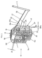
- the matrix print head shown in FIG. 1 represents a serial matrix needle print head which is arranged with a needle stroke distance 1 opposite a pressure abutment 2.
- the printing needles 4 form one or more vertical needle gaps of, for example, 2 ⁇ 9 or 2 in the mouthpiece 5 x 12 printing needles.
- the printing needles 4 are held and guided in their entirety in a printing needle guide housing 7 with support levels 8.
- the printing needles 4 extend into a rear printing needle drive housing 9, which is closed by a cover 10.
- the cover 10 has cooling fins 11 for dissipating heat, which Magnet drives 12 arises.
- a magnetic drive 12 is assigned to each print needle 4 in the print needle drive housing 9.
- Each magnetic drive 12 consists of a magnetic yoke 13.
- Each magnetic yoke 13 consists of two magnetic yoke legs 13a and 13b and a magnetic yoke base 13c.
- An electromagnetic coil 14 is pushed onto a magnetic yoke leg 13a, 13b.
- Each magnet drive 12 also includes an armature 15, which can be pivoted by means of a pin bearing 16 and bears in a rearward position against a stop 18 by means of a spring 17, a working air gap 20 to be described in more detail between the armature 15 and a magnet yoke leg end face 19 is formed.
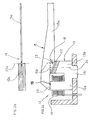
- a recess 22 in the magnetic yoke 13, extending in the longitudinal direction of the armature 15, is arranged in the center of the magnetic yoke thickness 21, which extends partly horizontally, partly obliquely (FIG. 1) or only obliquely (FIG. 2a).
- a central arm 15a of the armature 15 engages in the recess 22, which guides the armature 15 very precisely and thereby avoids lateral transverse movements which would be undesirable.
- the central arm 15a is rotatably supported by means of a bearing pin 23 of the pin bearing 16 and the pin axis 23a runs laterally in the region of the center of the magnetic yoke leg 24.
- a guide sword 15b is attached to the armature arm 15a or to a trapezoidal cross section 28 for precise lateral guidance.
- This area lies more on the magnetic yoke side surface 25 and can e.g. as drawn in FIG. 2, coincide with the plane of the magnetic yoke leg side surface 25.
- the pin axis 23a is in no case to be arranged in the middle of one of the magnetic yoke legs 13a or 13b.
- the recess 22 runs exclusively at an angle and part of the armature arm 15a, here designated 15b, projects into the recess 22 in.
- the horizontal pin axis 23a extends laterally to the area of the magnet yoke leg center 24, this time in the area of the radially outer magnet yoke leg side surface 25.
- the pin bearing 16 according to FIG. 2 forms an eye 26 which can be produced by punching lamellae as described below.
- Both the armature 15 and the magnetic yoke 13 are formed from laminations 27 stacked one on top of the other, at least one central recess 22 having the thickness 28a of one laminate 27 (or also of several laminations) being present and the one laminate 27 (or more) the armature arm 15a the anchor (15).
- the armature 15 closes exactly above the two magnetic yoke legs 13a, 13b and is provided with an approximately trapezoidal cross section 28.
- Both the armature 15 and the magnetic yoke 13 can be held together by rivets, spot welding or pressure pin connections 29.
- the armature 15 and the magnetic yoke 13, on the other hand can also be produced in one piece in sintering tools with the outer shape shown.
- lubricant is also stored between the individual lamellae 27, which e.g. can consist of graphite or heat-resistant oils of a natural or synthetic nature.
- FIGS. 2 and 3 and 4 respectively, form a magnetic yoke 13 with an armature 15 or armature arm 15a and a pin 23 in the assembled state of the electromagnetic coil (this is not shown in FIGS. 2 and 3) a unit.
- the assembly unit according to FIG. 3 is designed differently. Although the greatest width of the arm 15a is also in the region of the pin bearing 16 here, the profile of the arm 15a is continuous on the "underside", but discontinuous on the "top”. The discontinuous course 37 results in a higher vibration rigidity depending on the application.
Landscapes
- Impact Printers (AREA)
- Facsimile Heads (AREA)
- Particle Formation And Scattering Control In Inkjet Printers (AREA)
Claims (6)
- Tête d'impression matricielle, en particulier tête d'impression matricielle à aiguilles en série, qui est agencée avec un écartement correspondant à la course des aiguilles (1) par rapport à une butée d'impression (2), sur laquelle repose un support d'enregistrement (3), et par rapport à un ruban encreur (6) guidé devant celui-ci, et qui présente un boîtier de guidage des aiguilles d'impression (7) et un boîtier d'entraînement des aiguilles d'impression (9), un entraînement magnétique (12) étant associé à chaque aiguille d'impression (4) dans le boîtier d'entraînement des aiguilles d'impression (9), entraînement magnétique constitué d'une culasse d'aimant (13), sur une branche (13a) de laquelle est agencée une bobine électromagnétique (14), et de plus d'une armature (15) qui peut pivoter au moyen d'une suspension à broches (16) et repose contre une butée (18) au moyen d'un ressort (17) dans une position arrière, un entrefer de travail (20) étant formé entre l'armature (15) et une face frontale (19) de la branche de la culasse d'aimant,
caractérisée en ce que, de façon centrale par rapport à l'épaisseur (21) de la culasse d'aimant, est prévu un évidement (22) dans lequel un bras central (15a) de l'armature (15) est monté pivotant au moyen de la broche (23), l'axe (23a) de la broche s'étendant latéralement à la zone du centre (24) de la branche de la culasse d'aimant, c'est-à-dire dans la zone de la face latérale (25) de la branche (13a,13b) de la culasse d'aimant. - Tête d'impression matricielle selon la revendication 1,
caractérisée en ce que, sur le côté de l'armature (15) opposé à la face frontale (19) de la culasse d'aimant, il est prévu au moins une aile de guidage (15b), qui s'engage dans l'évidement (22) de la culasse d'aimant (13), dans laquelle s'étend l'axe (23a) de la broche. - Tête d'impression matricielle selon les revendications 1 et 2,
caractérisée en ce qu'aussi bien l'armature (15) que la culasse d'aimant (13) sont constituées de lamelles (27) disposées l'une sur l'autre, au moins un évidement médian (22) ayant l'épaisseur (28a) d'une lamelle (27), qui forme le bras (15a) de l'armature, étant prévu, et en ce que l'armature (15), au-dessus des deux branches (13a,13b) de la culasse d'aimant, est réalisée en ayant une section transversale (28) sensiblement trapézoïdale. - Tête d'impression matricielle selon les revendications 1 à 3,
caractérisée en ce que des lubrifiants sont prévus entre les lamelles individuelles (27). - Tête d'impression matricielle selon une ou plusieurs des revendications 1 à 4,
caractérisée en ce qu'une culasse d'aimant (13) avec une armature (15) ou un bras (15a) d'armature et une broche (23) forment, dans l'état monté de la bobine électromagnétique (14), une unité. - Procédé pour fabriquer un entraînement magnétique (12) pour des têtes d'impression matricielles, en particulier pour des têtes d'impression matricielles à aiguilles en série, qui est constitué, à chaque fois, d'une culasse d'aimant (13), sur une branche (13a,13b) de laquelle est agencée une bobine électromagnétique (14), et de plus d'une armature (15) qui peut pivoter au moyen d'une suspension à broches (16),
caractérisé en ce que les étapes de procédé suivantes sont effectuées successivement :1. estampage des lamelles (27) de la culasse d'aimant par un moule externe et pré-estampage d'un trou pour la suspension à broches (16) latéralement à la zone du centre (24) de la branche de la culasse d'aimant, c'est-à-dire dans la zone de la face latérale (25) de la branche (13a,13b) de la culasse d'aimant,2. empilage des lamelles de la culasse d'aimant ainsi estampées dans le but de fabriquer un trou pour une broche à diamètre brut,3. calibrage du trou de broche brut,4. mise en place de l'armature (15) sans aiguilles (4) ou de l'armature (15) avec des aiguilles (4) de sorte qu'une lamelle médiane (27) de l'armature s'engage dans un évidement central (22) entre deux empilages (30,31) de lamelles,5. alignement de l'armature sur les arêtes externes (32,33) de la culasse d'aimant (13),6. mise en place d'un poinçon (34) dans le trou calibré pour la broche, perçage de la lamelle (35) de l'armature, l'armature (15) reposant sans entrefer sur la face frontale (19) de la branche de la culasse d'aimant, et le poinçon (34) demeurant, en même temps, comme broche de palier (23).
Priority Applications (5)
| Application Number | Priority Date | Filing Date | Title |
|---|---|---|---|
| AT89250118T ATE103538T1 (de) | 1989-12-18 | 1989-12-18 | Matrixdruckkopf, insbesondere serieller matrixnadeldruckkopf. |
| EP89250118A EP0433497B1 (fr) | 1989-12-18 | 1989-12-18 | Tête d'impression en matrice de points et particulièrement tête d'impression en matrice de points à aiguilles pour impression en série |
| DE89250118T DE58907361D1 (de) | 1989-12-18 | 1989-12-18 | Matrixdruckkopf, insbesondere serieller Matrixnadeldruckkopf. |
| JP2337026A JPH03190755A (ja) | 1989-12-18 | 1990-11-30 | ドットマトリクスプリンタヘッド |
| US07/628,715 US5290112A (en) | 1989-12-18 | 1990-12-17 | Matrix print head, in particular serial matrix pin print head |
Applications Claiming Priority (1)
| Application Number | Priority Date | Filing Date | Title |
|---|---|---|---|
| EP89250118A EP0433497B1 (fr) | 1989-12-18 | 1989-12-18 | Tête d'impression en matrice de points et particulièrement tête d'impression en matrice de points à aiguilles pour impression en série |
Publications (2)
| Publication Number | Publication Date |
|---|---|
| EP0433497A1 EP0433497A1 (fr) | 1991-06-26 |
| EP0433497B1 true EP0433497B1 (fr) | 1994-03-30 |
Family
ID=8202550
Family Applications (1)
| Application Number | Title | Priority Date | Filing Date |
|---|---|---|---|
| EP89250118A Expired - Lifetime EP0433497B1 (fr) | 1989-12-18 | 1989-12-18 | Tête d'impression en matrice de points et particulièrement tête d'impression en matrice de points à aiguilles pour impression en série |
Country Status (5)
| Country | Link |
|---|---|
| US (1) | US5290112A (fr) |
| EP (1) | EP0433497B1 (fr) |
| JP (1) | JPH03190755A (fr) |
| AT (1) | ATE103538T1 (fr) |
| DE (1) | DE58907361D1 (fr) |
Families Citing this family (18)
| Publication number | Priority date | Publication date | Assignee | Title |
|---|---|---|---|---|
| JP2567150Y2 (ja) * | 1991-01-31 | 1998-03-30 | シチズン時計株式会社 | 印字ヘッド |
| JP4592159B2 (ja) * | 2000-06-30 | 2010-12-01 | 三菱重工業株式会社 | 電磁クラッチおよび該電磁クラッチを備えた圧縮機 |
| US6682233B2 (en) * | 2002-03-18 | 2004-01-27 | Toshiba Tec Kabushika Kaisha | Supporting structure of an armature of a wire dot printer head |
| US7314323B2 (en) * | 2003-09-03 | 2008-01-01 | Toshiba Tec Kabushiki Kaisha | Wire dot printer head and wire dot printer |
| US7008126B2 (en) * | 2003-09-04 | 2006-03-07 | Toshiba Tec Kabushiki Kaisha | Wire dot printer head and wire dot printer |
| US20050076866A1 (en) * | 2003-10-14 | 2005-04-14 | Hopper Mark L. | Electromechanical valve actuator |
| US7172351B2 (en) * | 2004-01-26 | 2007-02-06 | Toshiba Tec Kabushiki Kaisha | Method for manufacturing an armature |
| JP2005254665A (ja) * | 2004-03-12 | 2005-09-22 | Toshiba Tec Corp | アーマチュア、ワイヤドットプリンタヘッド及びワイヤドットプリンタ |
| JP2005254663A (ja) * | 2004-03-12 | 2005-09-22 | Toshiba Tec Corp | ワイヤドットプリンタヘッド及びワイヤドットプリンタ |
| JP4562406B2 (ja) * | 2004-03-12 | 2010-10-13 | 東芝テック株式会社 | ワイヤドットプリンタヘッド及びワイヤドットプリンタ |
| JP4515121B2 (ja) * | 2004-03-15 | 2010-07-28 | 東芝テック株式会社 | ワイヤドットプリンタヘッド及びワイヤドットプリンタ |
| JP2005254732A (ja) * | 2004-03-15 | 2005-09-22 | Toshiba Tec Corp | ワイヤドットプリンタヘッド及びワイヤドットプリンタ |
| JP4473021B2 (ja) * | 2004-03-22 | 2010-06-02 | 東芝テック株式会社 | 窒化層形成方法、磁気回路形成部材、アーマチュア、ワイヤドットプリンタヘッド及びワイヤドットプリンタ |
| JP2005262803A (ja) * | 2004-03-22 | 2005-09-29 | Toshiba Tec Corp | ヨークの製造方法、ヨーク、ワイヤドットプリンタヘッド及びワイヤドットプリンタ |
| JP4628689B2 (ja) * | 2004-03-23 | 2011-02-09 | 東芝テック株式会社 | ワイヤドットプリンタヘッド及びワイヤドットプリンタ |
| JP4589023B2 (ja) * | 2004-03-23 | 2010-12-01 | 東芝テック株式会社 | アーマチュア、ワイヤドットプリンタヘッド及びワイヤドットプリンタ |
| JP2007083622A (ja) * | 2005-09-22 | 2007-04-05 | Toshiba Tec Corp | ドットヘッド及びドットヘッド用アーマチュア構体の製造方法 |
| JP4606988B2 (ja) * | 2005-10-06 | 2011-01-05 | 東芝テック株式会社 | アーマチュア構体及びドットヘッド |
Family Cites Families (19)
| Publication number | Priority date | Publication date | Assignee | Title |
|---|---|---|---|---|
| DE2003643C3 (de) * | 1970-01-28 | 1975-08-28 | Siemens Ag | Aus Blechen zusammengesetzter Magnetkern |
| US4167343A (en) * | 1976-09-27 | 1979-09-11 | Golobay Gary L | Print wire actuator mechanism |
| US4242004A (en) * | 1979-03-21 | 1980-12-30 | Extel Corporation | Dot matrix printhead driver |
| JPS56120356A (en) * | 1980-02-29 | 1981-09-21 | Citizen Watch Co Ltd | Dot matrix printer |
| JPS5761589A (en) * | 1980-10-01 | 1982-04-14 | Hitachi Ltd | Printer |
| JPS57165267A (en) * | 1981-04-03 | 1982-10-12 | Hitachi Ltd | Wire matrix type printing head and assembling method thereof |
| JPS5820469A (ja) * | 1981-07-30 | 1983-02-05 | Matsushita Electric Ind Co Ltd | 印字装置 |
| JPS5855255A (ja) * | 1981-09-30 | 1983-04-01 | Hitachi Ltd | ドツトプリンタヘツドのコイル端子半田付方法 |
| JPS58155705A (ja) * | 1982-03-12 | 1983-09-16 | Canon Electronics Inc | 磁気コア |
| JPS6048372A (ja) * | 1983-08-26 | 1985-03-16 | Hitachi Ltd | 印字ヘツド |
| JPS6067170A (ja) * | 1983-09-26 | 1985-04-17 | Tokyo Electric Co Ltd | ドツトプリンタヘツド |
| EP0152117A3 (fr) * | 1984-02-16 | 1987-05-27 | Dataproducts Corporation | Dispositif de commande pour tête d'impression matricielle par points |
| US4767227A (en) * | 1985-01-25 | 1988-08-30 | Seiko Epson Corporation | Print wire driving device for wire type dot printer |
| DE3706730A1 (de) * | 1987-03-02 | 1988-09-15 | Nixdorf Computer Ag | Nadeldruckkopf |
| JPS63302061A (ja) * | 1987-06-02 | 1988-12-08 | Fuji Electric Co Ltd | ワイヤドットプリンタの印字ヘッド |
| DE3879930D1 (de) * | 1988-04-22 | 1993-05-06 | Mannesmann Ag | Verfahren zum herstellen von ankern des elektromagnetspulen-anker-systems fuer matrixdruckkoepfe und anker, insbes. der klappankerbauart. |
| EP0341930A3 (fr) * | 1988-05-10 | 1990-01-10 | Tokyo Electric Co., Ltd. | Tête d'impression par points du type à déclenchement |
| ATE84468T1 (de) * | 1988-08-31 | 1993-01-15 | Mannesmann Ag | Matrixnadeldruckkopf der klappankerbauart. |
| DE68913933T2 (de) * | 1988-12-19 | 1994-07-21 | Seiko Epson Corp | Punktnadelanschlagdrucker. |
-
1989
- 1989-12-18 AT AT89250118T patent/ATE103538T1/de not_active IP Right Cessation
- 1989-12-18 DE DE89250118T patent/DE58907361D1/de not_active Expired - Fee Related
- 1989-12-18 EP EP89250118A patent/EP0433497B1/fr not_active Expired - Lifetime
-
1990
- 1990-11-30 JP JP2337026A patent/JPH03190755A/ja active Pending
- 1990-12-17 US US07/628,715 patent/US5290112A/en not_active Expired - Fee Related
Non-Patent Citations (2)
| Title |
|---|
| PATENT ABSTRACTS OF JAPAN vol. 5, no. 80 (M-70)(752) 26 May 1981; JP-A-56 28879 * |
| PATENT ABSTRACTS OF JAPAN vol.10, no. 66(M-461)(2123) 15 March 1986; JP-A-60 212362 * |
Also Published As
| Publication number | Publication date |
|---|---|
| DE58907361D1 (de) | 1994-05-05 |
| EP0433497A1 (fr) | 1991-06-26 |
| ATE103538T1 (de) | 1994-04-15 |
| US5290112A (en) | 1994-03-01 |
| JPH03190755A (ja) | 1991-08-20 |
Similar Documents
| Publication | Publication Date | Title |
|---|---|---|
| EP0433497B1 (fr) | Tête d'impression en matrice de points et particulièrement tête d'impression en matrice de points à aiguilles pour impression en série | |
| CH668335A5 (de) | Vorrichtung zum verbinden elektrischer leiter. | |
| DE2167021A1 (de) | Druckdrahtfuehrung | |
| EP1016105B1 (fr) | Procede et dispositif de fabrication de paquets formes de lames de toles pour noyaux magnetiques | |
| DE2630931B2 (de) | Antriebseinrichtung für einen Nadeldrucker | |
| DE1214898B (de) | Einteiliger Diapositiv-Rahmen | |
| DE2910859A1 (de) | Druckkopf fuer einen rasterdrucker | |
| DE112022002915T5 (de) | Spulenformgebungsvorrichtung für Statorspleißblöcke | |
| DE2810145C2 (de) | Führung für die Drucknadelenden eines Nadeldruckkopfes | |
| DE1245627B (de) | Druckhammereinrichtung | |
| DE2629267A1 (de) | Antriebsvorrichtung fuer einen draht-matrixdrucker | |
| DE3107512A1 (de) | Kipphebel-anordnung einer brennkraftmaschine mit innerer verbrennung | |
| EP0188671B1 (fr) | Procédé de fabrication d'un agencement de construction d'armatures pour têtes d'impression en matrices | |
| DE2323402A1 (de) | Elektromagnetischer uebertragerkopf | |
| DE2445438A1 (de) | Elektromagnetisches antriebselement fuer den schreibkopf eines punktmatrixschreibers sowie fuer eine verwendung des antriebselementes geeigneter schreibkopf | |
| DE2924672A1 (de) | Nadeldruckwerk | |
| DE68911278T2 (de) | Punktmatrixdrucker mit Anschlagdruckkopf. | |
| EP0040883A2 (fr) | Imprimante par points avec ajustement magnétique de la tête d'impression | |
| DE2713886C2 (de) | Vorrichtung zum Führen der Druckernadeln in einem Mosaiknadeldruckwerk | |
| EP0371182B1 (fr) | Tête d'impression matricielle à aiguilles du type à armature battante | |
| DE2100591B2 (de) | Aufzeichnung^- und/oder Wiedergabegerät | |
| DE3333252C2 (de) | Verfahren zur Herstellung eines Nadeldruckkopfes | |
| DE2947398A1 (de) | Schreibkopf fuer nadeldruckwerke | |
| DE2728093C2 (fr) | ||
| DE102022120095A1 (de) | Führungsbacke |
Legal Events
| Date | Code | Title | Description |
|---|---|---|---|
| PUAI | Public reference made under article 153(3) epc to a published international application that has entered the european phase |
Free format text: ORIGINAL CODE: 0009012 |
|
| 17P | Request for examination filed |
Effective date: 19901227 |
|
| AK | Designated contracting states |
Kind code of ref document: A1 Designated state(s): AT BE CH DE FR GB IT LI NL |
|
| 17Q | First examination report despatched |
Effective date: 19930218 |
|
| GRAA | (expected) grant |
Free format text: ORIGINAL CODE: 0009210 |
|
| AK | Designated contracting states |
Kind code of ref document: B1 Designated state(s): AT BE CH DE FR GB IT LI NL |
|
| PG25 | Lapsed in a contracting state [announced via postgrant information from national office to epo] |
Ref country code: IT Free format text: LAPSE BECAUSE OF FAILURE TO SUBMIT A TRANSLATION OF THE DESCRIPTION OR TO PAY THE FEE WITHIN THE PRE;WARNING: LAPSES OF ITALIAN PATENTS WITH EFFECTIVE DATE BEFORE 2007 MAY HAVE OCCURRED AT ANY TIME BEFORE 2007. THE CORRECT EFFECTIVE DATE MAY BE DIFFERENT FROM THE ONE RECORDED.SCRIBED TIME-LIMIT Effective date: 19940330 Ref country code: NL Effective date: 19940330 Ref country code: BE Effective date: 19940330 |
|
| REF | Corresponds to: |
Ref document number: 103538 Country of ref document: AT Date of ref document: 19940415 Kind code of ref document: T |
|
| REF | Corresponds to: |
Ref document number: 58907361 Country of ref document: DE Date of ref document: 19940505 |
|
| GBT | Gb: translation of ep patent filed (gb section 77(6)(a)/1977) |
Effective date: 19940627 |
|
| EN | Fr: translation not filed | ||
| PG25 | Lapsed in a contracting state [announced via postgrant information from national office to epo] |
Ref country code: FR Effective date: 19940826 |
|
| NLV1 | Nl: lapsed or annulled due to failure to fulfill the requirements of art. 29p and 29m of the patents act | ||
| PG25 | Lapsed in a contracting state [announced via postgrant information from national office to epo] |
Ref country code: AT Effective date: 19941218 |
|
| PG25 | Lapsed in a contracting state [announced via postgrant information from national office to epo] |
Ref country code: LI Effective date: 19941231 Ref country code: CH Effective date: 19941231 |
|
| PLBE | No opposition filed within time limit |
Free format text: ORIGINAL CODE: 0009261 |
|
| STAA | Information on the status of an ep patent application or granted ep patent |
Free format text: STATUS: NO OPPOSITION FILED WITHIN TIME LIMIT |
|
| 26N | No opposition filed | ||
| REG | Reference to a national code |
Ref country code: CH Ref legal event code: PL |
|
| PGFP | Annual fee paid to national office [announced via postgrant information from national office to epo] |
Ref country code: FR Payment date: 19951120 Year of fee payment: 7 |
|
| EN | Fr: translation not filed |
Free format text: BO 94/34 PAGES 158 IL Y A LIEU DE SUPPRIMER:LA MENTION DE LA NON REMISE DE LA TRADUCTION |
|
| ET | Fr: translation filed | ||
| PGFP | Annual fee paid to national office [announced via postgrant information from national office to epo] |
Ref country code: GB Payment date: 19961113 Year of fee payment: 8 |
|
| REG | Reference to a national code |
Ref country code: FR Ref legal event code: ST |
|
| PG25 | Lapsed in a contracting state [announced via postgrant information from national office to epo] |
Ref country code: GB Free format text: LAPSE BECAUSE OF NON-PAYMENT OF DUE FEES Effective date: 19971218 |
|
| GBPC | Gb: european patent ceased through non-payment of renewal fee |
Effective date: 19971218 |
|
| PGFP | Annual fee paid to national office [announced via postgrant information from national office to epo] |
Ref country code: DE Payment date: 20041231 Year of fee payment: 16 |
|
| PG25 | Lapsed in a contracting state [announced via postgrant information from national office to epo] |
Ref country code: DE Free format text: LAPSE BECAUSE OF NON-PAYMENT OF DUE FEES Effective date: 20060701 |