EP0433512A1 - Verfahren und Gerät zur Abschätzung oder Messung der Haftkenngrössen einer auf die rauhe Oberfläche eines Substrats aufgebrachten Dünnschicht bzw. der Versteifungselemente eines aus zusammengesetztem oder uniformem Material bestehenden Körpers - Google Patents
Verfahren und Gerät zur Abschätzung oder Messung der Haftkenngrössen einer auf die rauhe Oberfläche eines Substrats aufgebrachten Dünnschicht bzw. der Versteifungselemente eines aus zusammengesetztem oder uniformem Material bestehenden Körpers Download PDFInfo
- Publication number
- EP0433512A1 EP0433512A1 EP89403547A EP89403547A EP0433512A1 EP 0433512 A1 EP0433512 A1 EP 0433512A1 EP 89403547 A EP89403547 A EP 89403547A EP 89403547 A EP89403547 A EP 89403547A EP 0433512 A1 EP0433512 A1 EP 0433512A1
- Authority
- EP
- European Patent Office
- Prior art keywords
- stud
- rod
- thin layer
- deformable material
- adhesive
- Prior art date
- Legal status (The legal status is an assumption and is not a legal conclusion. Google has not performed a legal analysis and makes no representation as to the accuracy of the status listed.)
- Withdrawn
Links
Images


Classifications
-
- G—PHYSICS
- G01—MEASURING; TESTING
- G01N—INVESTIGATING OR ANALYSING MATERIALS BY DETERMINING THEIR CHEMICAL OR PHYSICAL PROPERTIES
- G01N19/00—Investigating materials by mechanical methods
- G01N19/04—Measuring adhesive force between materials, e.g. of sealing tape, of coating
Definitions
- the present invention relates to a method and an apparatus for evaluating or measuring the characteristics of the adhesion properties of a thin layer applied to the rough surface of a substrate or of reinforcing elements of a body made of composite material or aggregate.
- Such a thin layer can be constituted by a layer of paint, any coating, an electronic component or even any other body linked to the substrate by implementing weak physical bonds (Van der Waals forces) or strong chemical bonds ( covalent), or else a mechanical adhesion, by anchoring, or of the type known as "VELCRO", a magnetic bond or a combination of these different types of bond.
- the object of the present invention is to provide a method and an apparatus which are very easy to implement and which make it possible to obtain, in a particularly simple manner, precise information making it possible to characterize the adhesion forces.
- this method of evaluating or measuring the characteristics of the adhesion properties of a thin layer applied to the rough surface of a substrate or of reinforcing elements of a body made of composite material or aggregate is characterized in what is made to adhere a pad of deformable material to the surface of the thin layer or to a surface of the body, a force is exerted on the pad or on the body, and the surface deformations of the pad made of deformable material are measured, deformations allowing to characterize the adhesion properties of the thin layer or of the reinforcing elements.
- the subject of the invention is also an apparatus for evaluating or measuring the characteristics of the adhesion properties of a thin layer applied to the rough surface of a substrate, characterized in that it comprises a stud made of deformable material, means for ensuring a connection, permanent or not permanent, between the stud of deformable material and the thin layer or the body, means for exerting a force on the stud of deformable material or on the body, and means for measuring the surface deformations of the pad of deformable material, deformations which depend on the behavior of the thin layer or of the body.
- the method according to the invention is intended to evaluate or measure the characteristics of the adhesion properties of a film or of a thin layer 1, such as a layer of paint, which adheres, by its lower face 1a, to the rough upper surface 2a, also called "subjective", of a substrate 2.
- a pad 3 is used. deformable material which is made to adhere to the external surface 1b of the thin layer 1.
- This stud 3 has a constant thickness and it is constituted by a prismatic or cylindrical block.
- connection between the pad made of deformable material 3 and the thin layer 1 can be produced by means of a cold or hot polymerizing adhesive, a self-adhesive double-sided adhesive film or in general of any body having an ability to bind to the thin layer 1 and the pad 3. It is also possible to use, for ensuring the connection between the pad of deformable material 3 and the thin layer 1, the grafting of free radicals having a high affinity, so that bonding can be carried out at moment of contact or by catalysis or by the action of a thermal or magnetic field.
- the deformations of the pad 3 are measured and for this purpose one can use a well-known method such as extensometry, photoelasticimetry with laser if the pad 3 is made of a transparent material having photoelastic properties, the Speckle if one wants to measure the surface displacements, photoelasticimetry by reflection, laser methods, mechanical extensometry etc.
- extensometry is used which offers the advantage of making it possible to measure not only the deformations of the pad 3 but also the intensity of the force of traction F.
- the free upper surface 3a of the stud 3 is applied, that is to say that which is located opposite the face adhering to the thin layer 1, and possibly on its lateral surface 3b.
- electrical strain gauges J1, J2 ... Jn, Jp which are connected to an extensometry device 5.
- An additional strain gauge Jt can be incorporated into element 6, such as a rod, transmitting the tensile force F at stud 3, in order to measure the intensity of this force.
- the sensor 7 is associated with the force transmission rod 6 while the sensor 8 is associated with the substrate 2
- the method according to the invention can also be used to study the behavior of the thin layer 1 when it is subjected to compression.
- the intermediate adhesive layer 4 can be removed and the pad 3 can be applied directly to the upper surface of the thin layer 1.
- the connection can then be ensured by an adherent mechanical anchoring, the roughness of the surface of the thin layer 1 then being sufficient to ensure adhesion.
- the curves giving the variation of the force F applied as a function of the surface deformation ⁇ i appearing make it possible to detect the appearance of the first microcracks when slope changes occur. Any change of state such as a passage from an elastic behavior to an elastoplastic behavior or to a damage by cracks etc. releases energy and the form of this energy characterizes the nature of the body in evolution.
- Experiments carried out on structures bonded by acoustic emission and extensometry by electrical gauges have shown that the deformations of the structure are linked and well correlated with acoustic emission.
- the method and apparatus according to the invention make it possible to determine the initiation of the first cracks and to link them to the surface deformations ⁇ i.
- the acoustic spectrum makes it possible to know which part is damaged and when the damage occurs.
- the acoustic spectrum on the one hand and the deformation curves of the pad 3 on the other hand are different depending on whether the initiation of microcrack formation occurs in the thin layer 1 or in the substrate 2.
- the acoustic spectrum on the one hand and the deformation curves of the pad 3 on the other hand are different if the initiation of rupture occurs by local detachment at the interface between the thin layer 1 and the substrate 2.
- the acoustic spectrum and the Extensometry curves make it possible to differentiate the ruptures which can be of the adhesive rupture type or of the cohesive rupture type. Finally, these two types of curves will be different if the roughness at the interface between the thin layer 1 and the substrate 2 is different and if the physical, physicochemical or chemical treatment of the substrate 2a of the substrate 2 is different. It should be noted that the acoustic spectrum makes it possible to measure a precise thickness of the thin layer, which varies as a function of the roughness of the substrate 2a to which the thin layer 1 adheres, for an application of constant volume on the substrate 1a.
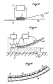
- FIG. 2 illustrates the use of the device according to the invention on rigid or flexible substrates, or even even modular in any direction at constant volume such as rubbers.
- the pad 3 is shown adhering permanently to a rigid substrate 2 while in the central part of this figure it is applied to a flexible substrate 2, adhering in a non-permanent manner , and that in the right part of FIG. 2 it is applied to a rigid support 2 while also adhering in a non-permanent manner.
- FIG. 3 illustrates a particularly simple embodiment of the measuring apparatus in which the pad 3 is replaced by a set of three flexible sheets 11, 12, 13 of the self-adhesive type with non-permanent adhesion, for example those known under the mark "Post-it".
- These sheets are sheets of paper that can be glued and unglued at will on all supports provided they are not soiled.
- the three sheets 11, 12, 13 are assembled together by their self-adhesive parts and the upper sheet 13 carries, on its glued part, an extensometry gauge J connected to the extensometric measuring device 5.
- the upper sheet 13 can be pulled in different directions as shown by arrow F.
- FIGS. 4 and 5 illustrate a sheet 14 of flexible material, self-adhesive on its two faces and which can be applied and glued, by its lower face, to the thin layer 1.
- This bonding can be permanent or non-permanent and in the latter case the entire apparatus can be easily recovered by peeling to be reused elsewhere in the thin layer 2.
- the flexible sheet 14 bears on its upper face the strain gauges J1..Jn which adhere by bonding. These gauges can be protected by a layer of protective varnish 15, as shown in FIG. 5, or by a removable or non-removable adhesive film.
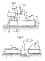
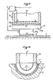
- FIG. 6 represents an embodiment of the assembly of an apparatus comprising means making it possible to exert a tensile force on the stud 3.
- the assembly of the apparatus comprises a support frame 16 in the form of a bell comprising an upper horizontal bottom 16a and a cylindrical peripheral skirt 16b extending downward and which is brought into contact, by its lower annular front face 16c, with the surface of the thin layer 1.
- This bearing face 16c is preferably non-slip, for example adhesive, ridged etc ...
- the stud 3 is housed inside the support frame 16 and its rod 6 extends vertically upward through a central hole 17 drilled in the upper bottom 16a of the frame 16
- a device 18 which is coupled to the upper end part of the rod 6 to exert on this rod a tensile force upwards.
- the device 18 exerting the tensile force comprises a nut 19 which is screwed onto the threaded end part 6a of the rod 6 of the stud 3 and which bears, at its lower part, on a ball bearing.
- spherical 21 carried by the upper face of the bottom 16a.
- the nut 19 has a small pitch to allow micrometric displacements.
- the device 18 allows, by screwing more or less the nut 19 on the thread 6a, to exercise, on the pad 3, a more or less intense tensile force F upwards, as indicated by the arrow, so that the nut 19 is pressed down on the spherical stop 21.
- the apparatus shown in FIG. 6 is also provided with a knife 22 which is carried by the lower part of the skirt 16b of the frame 16, outside of the latter as shown in FIG. 6 or else inside.
- This knife 22 is intended to cut the thin layer 1 over its entire thickness so as to delimit a washer on which the adhesion test is carried out.
- the knife 22 is mounted movable in rotation on the frame 16 around the vertical axis thereof, to ensure this cutting. It can be independent of the test device itself and constitute an autonomous cutting device, with guided penetration, having guaranteed stability on the structure.
- the knife 22 must be able to adapt to any surfaces, convex or concave, and for this purpose it can be constituted by a blade of flexible and deformable composite material, with teeth or smooth.
- the device can include as many knives as it has lateral faces, each knife then being movable parallel to the lateral face on which it is mounted.
- Such an apparatus then makes it possible to cut, in the thin layer 1, a wafer with a polygonal outline.
- the screw 6a-nut system 19 can be replaced by a hydraulic or pneumatic jack, the rod of which is coupled to the rod 6 of the stud 3 and the body of which bears on the upper bottom 16a of the frame 16.
- the device according to the invention comprises a stepped stud 23 which comprises an upper part 23a of large surface S1 which is extended by a central lower part 23b of smaller surface S2 which adheres to the thin layer 1 by means of the adhesive or the layer of glue 4 ensuring a permanent collage. Therefore the stud 23 can be left in place permanently and for the test is made to adhere to the upper face of its upper part 23a, via a low resistance bonding layer 24, the lower face d 'a rod 25 transmitting a tensile force F upwards.
- Figure 8 shows an apparatus implementing the principle illustrated in Figure 7 and in this case the rod 25 is tubular and it has, at its lower end, an internal thread 26 by which it is screwed onto a thread provided on the surface lateral of the upper part 23a of the stud 23.
- the rod 25 also has a thin thickness bottom 25a slightly set back and which carries on its upper face the strain gauges J1..Jn.
- the stud 23 is also glued, by the upper face of its upper part 23a, to the bottom 25a of the rod 25 by means of a non-permanent adhesive 24.
- the thread 26 ensures the anchoring of the rod 25 on the stud 23 and it allows the tensile force F to be transmitted to this stud 23.
- the adhesive film 24 transmits the deformations of the stud 23 to the thin bottom 25a of the rod 25, deformations which depend on the adhesion of the thin layer 1 on the substrate 2 and which are measured by the gauges J1..Jn.
- strain gauges can be provided on the lateral surface of the lower part 23b, of small surface S2, of the pad 23, as shown in FIG. 7, if the adhesive layer 4 provides a weak bond, as is the case of paper packaging, plastics, leather clothing and shoes, fabrics, "VELCRO" type bindings, etc.
- the tubular rod 25 is closed, at its lower end, by a thin transverse bottom 25a which adheres to the upper surface of the upper part 23a of the stud 23, by means of the adhesive layer 24 Therefore the connection between the rod 25 by which is exerted the tensile force F, and the pad 23 is provided only by the adhesive layer 24.
- the strain gauges J1..Jn are carried by the internal face of the bottom 25a of the rod 25 and they make it possible to remotely analyze what is happening in the layer of adhesive 4 between the lower part 23b of the pad 23 and the thin layer 1.
- the device according to the invention has been shown as applying to a flat surface, it goes without saying that it can be applied to concave or convex surfaces as shown in these Figures 10 and 11.
- the stud 3 of deformable material has a corresponding concave or convex shape.
- FIG. 12 illustrates an application of the apparatus according to the invention to the evaluation of the characteristics of the internal adhesion properties of a body 27 made of composite or aggregate material comprising, within it, elements of reinforcement such as fibers 28 in contact with a material constituting the matrix.
- the device also comprises in this case a stud made of deformable material 3 which is advantageously constituted by an elastic buffer of the rubber type.
- This stud 3 is glued, for example, to the underside of the body 27 resting on two supports 29 and which is subjected to a vertical force F exerted from top to bottom on its upper face.
- the elastic pad 3 carries on its underside the strain gauges J1 ...
- the device according to the invention can be applied in many other fields and in particular it can be implanted in artificial prostheses as it is represented in FIGS. 13 and 14.
- FIGS. 13 and 14 These figures represent a hip prosthesis 30 which comprises a ball joint 31 and a femoral tail 32 engaged in the head of a femur 33.
- the apparatus 34 according to the invention is located in the upper part of the femoral tail 32, in the bottom of a blind hole 35 closed by means of a screwed and glued stopper 36.
- the device 34 comprises, as in the cases illustrated above, a pad of deformable material 3 which is fixed in the bottom of the blind hole 35 by means of a layer of adhesive 4. This deformable pad 3 carries, on its free face, the gauges J1 ...
- the strain gauges J1 ... Jn can possibly be replaced by a telemetry system if one does not wish to have wires coming out of the prosthesis.
- the device 34 thus implanted makes it possible to measure the local deformations of the hip prosthesis 31 which works in flexion under the effect of the weight of the human body.
- the device according to the invention 34 can be adapted to any type of prosthesis and that it can be placed in any part of a prosthesis.
- FIG. 14 illustrates an alternative application in which the device 34 is implanted in the bone, in this case in the femur head 33.
- the device is held by the layer of compatible adhesive 4 binding the pad in deformable material 3 and by the plug 36 which is housed in the sealing cement 37.
- the assembly of the device 34 and the plug 36 can advantageously be surrounded by a flexible protective seal 38.
- FIG. 14 also illustrates the implementation possible place of a device 34 in the ball joint 31 of the prosthesis 30.
- the device 34 can also be implanted in a diseased bone before the operation, in order to determine real efforts and deformations of different parts of the head of the femur 34 for example. It can be installed to measure the actions of the male part of the prosthesis on the female part of it or vice versa.
- FIG. 15 illustrates an application of the apparatus according to the invention in the field of odontology.
- a miniaturized device 34 is used which is intended to measure the shearing effect, present or not, between a tooth 41 and a mass of cement 42 clogging a cavity.
- the device 34 is bonded to the tooth 41, by means of a two-sided adhesive 4 compatible with the ivory of the tooth, the device 34 comprising, as before, a stud 3 of deformable material carrying strain gauges J1 ... Jn connected to an extensometry device 5.
- This assembly allows a dentist to know if shears occur between the tooth 41 and the mass of cement 42.
- the shrinking cement acts on the tooth and causes a deformation of the adhesive 4 fixing the deformable pad 3 carrying the gauges.
- This device can also make it possible to adapt the roughness of the cavity and consequently the grinding stones to the cement, to study the composition of the cement and to adapt it to each patient.
- a dentist with several cements can perform interventions quickly, if necessary, in a limited time, since the cements harden quickly. If a cement is not suitable for a specific patient, he can then try another and judge its adhesion to the tooth.
- acoustic microsensors 43, 44 connected to an acoustic emission measuring device 45.
- the sensor 43 is fixed to the deformable stud 3 while the sensor 44 is fixed to the tooth 41 by means of '' a compatible adhesive serving as a binder between the tooth and the microsensor 44.
- the device thus makes it possible to test different cements and to judge their behavior in situ by comparison of the deformation or acoustic emission curves (by then providing mini-acoustic emission sensors installed between two neighboring teeth).
- the method and apparatus according to the invention can be used in very diverse fields and in particular for studying the behavior of skis or any other continuous composite structure.
- the device can in particular be installed on skis with a wire or telemetry outlet, to measure the behavior of skins or any delicate composite part to be tested in situ during skiing.
Landscapes
- Physics & Mathematics (AREA)
- Health & Medical Sciences (AREA)
- Life Sciences & Earth Sciences (AREA)
- Chemical & Material Sciences (AREA)
- Analytical Chemistry (AREA)
- Biochemistry (AREA)
- General Health & Medical Sciences (AREA)
- General Physics & Mathematics (AREA)
- Immunology (AREA)
- Pathology (AREA)
- Investigating Strength Of Materials By Application Of Mechanical Stress (AREA)
Applications Claiming Priority (1)
| Application Number | Priority Date | Filing Date | Title |
|---|---|---|---|
| FR8814451A FR2638846B1 (fr) | 1988-11-04 | 1988-11-04 | Procede et appareil d'evaluation ou de mesure des caracteristiques des proprietes d'adherence d'une couche mince appliquee sur la surface rugueuse d'un substrat ou d'elements de renforcement d'un corps en materiau composite ou agregat |
Publications (1)
| Publication Number | Publication Date |
|---|---|
| EP0433512A1 true EP0433512A1 (de) | 1991-06-26 |
Family
ID=9371600
Family Applications (1)
| Application Number | Title | Priority Date | Filing Date |
|---|---|---|---|
| EP89403547A Withdrawn EP0433512A1 (de) | 1988-11-04 | 1989-12-19 | Verfahren und Gerät zur Abschätzung oder Messung der Haftkenngrössen einer auf die rauhe Oberfläche eines Substrats aufgebrachten Dünnschicht bzw. der Versteifungselemente eines aus zusammengesetztem oder uniformem Material bestehenden Körpers |
Country Status (2)
| Country | Link |
|---|---|
| EP (1) | EP0433512A1 (de) |
| FR (1) | FR2638846B1 (de) |
Cited By (5)
| Publication number | Priority date | Publication date | Assignee | Title |
|---|---|---|---|---|
| DE29717736U1 (de) * | 1997-12-29 | 1998-05-20 | GMuG Gesellschaft für Materialprüfung und Geophysik mbH, 61239 Ober-Mörlen | Gerät zur zerstörungsfreien Ermittlung von Haftungsfehlern in Schichten, Verbundwerkstoffen und Werkstoffverbunden mit Hilfe der Schallemission |
| RU2134873C1 (ru) * | 1997-08-01 | 1999-08-20 | Военный автомобильный институт | Способ определения тангенциальной прочности адгезионной связи антифрикционных покрытий |
| FR2891365A1 (fr) * | 2005-09-28 | 2007-03-30 | Airbus France Sas | Plot de traction pour dispositif de test d'adherence d'un revetement sur un substart |
| CN116296835A (zh) * | 2022-09-06 | 2023-06-23 | 杭州电子科技大学 | 一种薄膜多孔介质材料弹塑性变形测量装置及方法 |
| CN116429679A (zh) * | 2023-03-31 | 2023-07-14 | 北京京仪自动化装备技术股份有限公司 | 大尺寸面板粘附力测试方法及装置 |
Families Citing this family (1)
| Publication number | Priority date | Publication date | Assignee | Title |
|---|---|---|---|---|
| FR2955654B1 (fr) * | 2010-01-25 | 2012-03-30 | Soitec Silicon Insulator Technologies | Systeme et procede d'evaluation de deformations inhomogenes dans des plaques multicouches |
Citations (2)
| Publication number | Priority date | Publication date | Assignee | Title |
|---|---|---|---|---|
| GB1179149A (en) * | 1967-11-11 | 1970-01-28 | Elecometer Instr Ltd | Improvements in Instruments for Testing the Adhesion of Coatings to Surfaces. |
| FR2570826A1 (fr) * | 1984-09-27 | 1986-03-28 | Exper Rech Etu Batimen Centre | Dispositif de mesure de la resistance a l'arrachement d'un materiau ou d'un composant mecanique de construction |
-
1988
- 1988-11-04 FR FR8814451A patent/FR2638846B1/fr not_active Expired - Lifetime
-
1989
- 1989-12-19 EP EP89403547A patent/EP0433512A1/de not_active Withdrawn
Patent Citations (2)
| Publication number | Priority date | Publication date | Assignee | Title |
|---|---|---|---|---|
| GB1179149A (en) * | 1967-11-11 | 1970-01-28 | Elecometer Instr Ltd | Improvements in Instruments for Testing the Adhesion of Coatings to Surfaces. |
| FR2570826A1 (fr) * | 1984-09-27 | 1986-03-28 | Exper Rech Etu Batimen Centre | Dispositif de mesure de la resistance a l'arrachement d'un materiau ou d'un composant mecanique de construction |
Non-Patent Citations (1)
| Title |
|---|
| JOURNAL OF VACUUM SCIENCE & TECHNOLOGY A, vol. 4, no. 6, série 2, novembre-décembre 1986, pages 3007-3014, American Vacuum Society, Woodbury, NY, US; J. VALLI: "A review of adhesion test methods for thin hard coatings" * |
Cited By (7)
| Publication number | Priority date | Publication date | Assignee | Title |
|---|---|---|---|---|
| RU2134873C1 (ru) * | 1997-08-01 | 1999-08-20 | Военный автомобильный институт | Способ определения тангенциальной прочности адгезионной связи антифрикционных покрытий |
| DE29717736U1 (de) * | 1997-12-29 | 1998-05-20 | GMuG Gesellschaft für Materialprüfung und Geophysik mbH, 61239 Ober-Mörlen | Gerät zur zerstörungsfreien Ermittlung von Haftungsfehlern in Schichten, Verbundwerkstoffen und Werkstoffverbunden mit Hilfe der Schallemission |
| FR2891365A1 (fr) * | 2005-09-28 | 2007-03-30 | Airbus France Sas | Plot de traction pour dispositif de test d'adherence d'un revetement sur un substart |
| WO2007036541A1 (fr) * | 2005-09-28 | 2007-04-05 | Airbus France | Plot de traction pour dispositif de test d'adherence d'un revetement sur un substrat |
| US8375780B2 (en) | 2005-09-28 | 2013-02-19 | Airbus Operations Sas | Traction pad for device testing adhesion of a coating on a substrate |
| CN116296835A (zh) * | 2022-09-06 | 2023-06-23 | 杭州电子科技大学 | 一种薄膜多孔介质材料弹塑性变形测量装置及方法 |
| CN116429679A (zh) * | 2023-03-31 | 2023-07-14 | 北京京仪自动化装备技术股份有限公司 | 大尺寸面板粘附力测试方法及装置 |
Also Published As
| Publication number | Publication date |
|---|---|
| FR2638846A1 (fr) | 1990-05-11 |
| FR2638846B1 (fr) | 1991-01-18 |
Similar Documents
| Publication | Publication Date | Title |
|---|---|---|
| EP3320219A1 (de) | Schraube mit extensometrischen dehnungsmessern zum messen der zug- und/oder scherdehnung der schraube | |
| EP0433512A1 (de) | Verfahren und Gerät zur Abschätzung oder Messung der Haftkenngrössen einer auf die rauhe Oberfläche eines Substrats aufgebrachten Dünnschicht bzw. der Versteifungselemente eines aus zusammengesetztem oder uniformem Material bestehenden Körpers | |
| FR2522407A1 (fr) | Dispositif de detection par contact, notamment pour robot | |
| FR2943129A1 (fr) | Dispositif de caracterisation tactile de texture de surface | |
| Rokhlin et al. | Modulated angle beam ultrasonic spectroscopy for evaluation of imperfect interfaces and adhesive bonds | |
| EP1308130B1 (de) | Vorrichtung zur Messung und/oder Analyse wenigstens eines Parameters von dem Aussenteil des menschlichen Körpers | |
| FR2867276A1 (fr) | Sonde tribo acoustique | |
| EP1473058B1 (de) | Vorrichtung zur Analyse der Haut mit einer Ultraschallprobe | |
| FR3050818A1 (fr) | Dispositif de mesure de deformations endogenes | |
| US4951497A (en) | Process and apparatus for measuring the roughness of the surface of a piece | |
| EP1883799A1 (de) | Ring zur messung der seitlichen verformung eines prüflings in uniaxialen oder triaxialen kompressionstests | |
| EP3275024B1 (de) | Ein piezoelektrischer sensor und ein instrument mit einem solchen sensor | |
| FR2696005A1 (fr) | Dispositif d'essais de traction à pistons et son utilisation pour des mesures d'adhérence. | |
| EP4264225A1 (de) | System zur messung der mechanischen eigenschaften einer hautprobe | |
| EP0336829B1 (de) | Vorrichtung und Verfahren zur Bestimmung des mechanischen Verhaltens von Klebstoffverbindungen an Oberflächen | |
| EP2667144B1 (de) | Verfahren zum Abschätzen der Rauheit einer Oberfläche | |
| FR2756632A1 (fr) | Procede de controle de l'integrite et de l'adherence d'un cordon de colle applique sur une tole, et installation pour la mise en oeuvre de ce procede | |
| Lloyd | Non-destructive testing of bonded joints: a case for testing laminated structures by wide-band ultrasound | |
| CA3199485A1 (fr) | Instrument de mesure de l'effort pour etaler une pate | |
| FR2919723A1 (fr) | Installation de mesure de repartition de force lineique d'un balai d'essuie-glace contre une surface a essuyer | |
| EP0251894B1 (de) | Verfahren zur Messung der Spannungskomponenten in transparenten photoelastischen Substraten, die durch Verleimen zusammengesetzt sind | |
| FR2830431A1 (fr) | Dispositif de mesure de caracteristiques de la peau et procede de mesure utilisant un tel dispositif | |
| BE1022509B1 (fr) | Bande adhésive multi-couches pour comprimer et contracter une cicatrice | |
| FR3092897A1 (fr) | Procédé de collage d’une jauge de contrainte sur un objet, tel un récipient de gaz | |
| Morel et al. | Scaling properties of contact area of pressure-sensitive adhesives |
Legal Events
| Date | Code | Title | Description |
|---|---|---|---|
| PUAI | Public reference made under article 153(3) epc to a published international application that has entered the european phase |
Free format text: ORIGINAL CODE: 0009012 |
|
| AK | Designated contracting states |
Kind code of ref document: A1 Designated state(s): AT BE CH DE ES GB GR IT LI LU NL SE |
|
| STAA | Information on the status of an ep patent application or granted ep patent |
Free format text: STATUS: THE APPLICATION IS DEEMED TO BE WITHDRAWN |
|
| 18D | Application deemed to be withdrawn |
Effective date: 19911227 |