EP0433545A2 - Cartouche de filet pour utilisation avec des cylindres de transfert et de sortie dans des machines rotatives d'impression - Google Patents
Cartouche de filet pour utilisation avec des cylindres de transfert et de sortie dans des machines rotatives d'impression Download PDFInfo
- Publication number
- EP0433545A2 EP0433545A2 EP90114865A EP90114865A EP0433545A2 EP 0433545 A2 EP0433545 A2 EP 0433545A2 EP 90114865 A EP90114865 A EP 90114865A EP 90114865 A EP90114865 A EP 90114865A EP 0433545 A2 EP0433545 A2 EP 0433545A2
- Authority
- EP
- European Patent Office
- Prior art keywords
- axle
- cylinder
- assembly
- cartridge
- roll
- Prior art date
- Legal status (The legal status is an assumption and is not a legal conclusion. Google has not performed a legal analysis and makes no representation as to the accuracy of the status listed.)
- Granted
Links
Images


Classifications
-
- B—PERFORMING OPERATIONS; TRANSPORTING
- B41—PRINTING; LINING MACHINES; TYPEWRITERS; STAMPS
- B41F—PRINTING MACHINES OR PRESSES
- B41F22/00—Means preventing smudging of machine parts or printed articles
Definitions
- This invention relates to printing presses, and more particularly to a new and improved cartridge assembly for providing a source of fabric net material to be used to cover the support surface of a transfer or delivery cylinder in a high speed, sheet fed off-set rotary printing press.
- the net material may be required to be adjusted to insure that the proper net tension over the cylinder is achieved for the particular printing job being run. This frequently requires that the press be stopped and the net tension adjusted by tightening the net slightly over the cylinder surface, since the net material may become stretched after prolonged use.
- the present invention provides a new and improved method and apparatus for permitting any amount of fabric net material to be replaced over the support surface of a transfer or delivery cylinder, and which is relatively simple in design, inexpensive to manufacture, yet is highly reliable in use and permits rapid net replacement and tension adjustment to minimize lost press production time.
- the present invention provides a cartridge assembly preferably mounted to the tail edge of a transfer or delivery cylinder and which supports a replaceable cartridge roll having a continuous supply of fabric net material wound thereon.
- the cartridge assembly and replaceable roll provide a source of supply of net material which can be quickly and easily advanced from the roll to replace any amount of old net material on the cylinder, from an amount sufficient to cover the entire support surface of the cylinder, to an amount sufficient to replace only a very small soiled or damaged portion of the net.
- the cartridge assembly includes a pair of mounting brackets attached to the inner surface of the cylinder adjacent each end, and which support an axle assembly on which the replaceable cartridge roll is mounted.
- the cartridge assembly preferably extends along the tail edge of the cylinder, and includes means for releasably mounting and locking the axle assembly to the brackets.
- Means are also provided to releasably lock the cartridge assembly against rotation in one direction relative to the brackets to prevent the net material from unwinding from the cartridge roll during press operation, yet which can be simply and quickly released to permit fabric net material to be unwound from the cartridge roll when ever desired.
- the releasable lock means includes a ratchet mechanism which permits the cartridge roll to be rotated in a direction to wind the fabric net material onto the roll without having to unlock the cartridge assembly, thereby to permit tightening adjustment of the net tension over the cylinder whenever net tensioning becomes necessary.
- FIGURE 1 is a perspective view of a transfer or delivery cylinder to which is mounted a cartridge assembly embodying the present invention, and illustrating the removal of fabric net material from the cartridge roll;
- FIG. 2 is an enlarged cross-sectional view of the cylinder of FIG. 1 taken substantially along line 2-2 thereof, and illustrating the net as attached over the cylinder and ready for use;
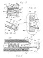
- FIG. 3 is a fragmentary exploded perspective view, partially in cross-section, illustrating the component parts of the cartridge assembly of the present invention
- FIG. 4 is an enlarged fragmentary exploded perspective view, partially in cross-section, of the component parts of the mounting bracket for supporting the right side end of the cartridge assembly as seen in FIG. 3;
- FIG. 5 is a further enlarged fragmentary cross-sectional view of the mounting bracket of FIG. 4 showing the cartridge assembly locked against rotation in one direction to prevent unwinding of the net material;
- FIG. 6 is a cross-sectional view similar to FIG. 5 showing the release of the cartridge assembly for free rotation relative to the mounting brackets;
- FIG. 7 is an enlarged fragmentary cross-sectional view of the mounting bracket for the left side of the cartridge assembly as shown in FIG. 3 and illustrating the cartridge assembly locked to the bracket against removal;
- FIG. 8 is an enlarged cross-sectional view taken substantially along line 8-8 of FIG. 7;
- FIG. 9 is a fragmentary cross-sectional view of the right side of the cartridge assembly as shown in FIG. 3 and showing the cartridge assembly in assembled form;
- FIG. 10 is a fragmentary perspective view of the right end of the cartridge assembly as shown in FIG. 9 but without the fabric net material wound thereon.
- the present invention is embodied in a cartridge assembly, generally designated by the reference numeral 10, intended to be used to provide a source of supply of ink repellant fabric material 12, referred to in the trade as a "net", for covering the outer support surface of a transfer or delivery wheel or cylinder 14 in a high speed, sheet fed off-set rotary printing press (not shown).
- the transfer or delivery cylinder 14 is of the general type illustrated and described in my aforementioned U.S. Patent No.
- 4,402,267 is intended to be mounted in a printing press to support the wet ink side of a printed sheet as the sheet is transferred from one processing station within the press to another or to the delivery end of the press, as is well understood by those skilled in the printing press art.
- the cylinder 14 is formed as a cylindrical shell having axially spaced ends 16 and an inner surface 18 and an outer support surface 20 which are discontinuous so as to form an axially extending opening defining a cylinder leading or gripper edge 22 and a cylinder trailing or tail edge 24, the opening being provided for cooperating with a gripper bar assembly (not shown) within the press which functions to withdraw and carry the printed sheet as it moves around the cylinder.
- the outer support surface 20 of the cylinder 14 is provided with a coating or covering of low friction material 30 over which the fabric net 12 is loosely disposed, the low friction coating permitting the net to cling to the printed sheet yet allowing the net to move relative to the support surface 20 of the cylinder 14 during transfer of a printed sheet, thereby to eliminate marking and marring of the wet ink surface.
- the net 12 which may be of the type manufactured and sold by Printing Research, Inc., of Dallas, Texas, under its registered trademark "SUPER BLUE”, preferably is formed from loosely woven cotton cloth treated with an ink repellant substance such as that manufactured by the 3M Manufacturing Company, Minneapolis, Minn. under its Part No. FC4101-C-12, and is formed to have an unstretched width substantially equal to the axial length of the cylinder 14 so as to extend completely across the support surface 20 between the axial ends 16 of the cylinder.
- the cartridge assembly 10 is mounted to the inner surface 20 of the cylinder 14 herein adjacent the tail edge 24, and supports a replaceable cartridge roll, herein generally designated by the reference numeral 32, about which is wound a continuous supply of fabric net material 12.
- the cartridge assembly 10 and replaceable cartridge roll 32 provide a source of supply of net material 12 which can be quickly and easily pulled from the roll over the support surface 20 of the cylinder 14 and attached to the gripper edge 22, herein by securing the end of the net to an attaching strip 34, preferably a strip of the type made under the trademark VELCRO, disposed along the inner surface 20 of the cylinder adjacent the gripper edge.
- the cartridge assembly 10 and removable cartridge roll 32 are constructed to operate in a highly reliable and effective manner to permit any amount of net material to be withdrawn from the roll, from an amount sufficient to provide a totally new net over the cylinder, to a very small amount sufficient to only replace a small portion of the net covering the cylinder, and when the supply of net material 12 has been exhausted from the roll, a new supply of net material can be quickly and easily replaced in the cartridge assembly.
- the cartridge assembly 10 includes a pair of mounting brackets 36 and 38, one disposed adjacent each axial end 16 of the cylinder 14, and which function to support an axle assembly 40 extending axially along the tail edge 24 of the cylinder between the brackets, and about which the cartridge roll 32 is disposed.
- each bracket 36 and 38 is formed as a generally rectangular block, preferably of metal, having a radially outer peripheral surface 42 formed with a curve corresponding to the curvature of the inner surface 18 of the cylinder 14, and is secured to the cylinder by counter-sunk screws 44 to project radially inwardly from the inner surface of the cylinder.
- Each bracket 36 and 38 is also provided with a blind cylindrical socket 46 dimensioned to receive one end of the axle assembly 40 for rotation therein, the sockets being formed to open toward each other along an axis parallel with the tail edge 24 of the cylinder 14 so that when the axle assembly 40 is mounted to the brackets, the center line of the axle assembly will be parallel with the tail edge and spaced radially inwardly from the inner surface 18 of the cylinder 14.
- the axle assembly 40 is formed to be removably mounted to the brackets 36 and 38 of the cylinder 14, and when the press is in use, will normally be locked against rotation in the clockwise direction as viewed from the left end in Fig. 1 relative to the brackets, to prevent the fabric net material 12 from unwinding from the cartridge roll 32 when the press is in use.
- the axle assembly 40 includes an elongated tubular axle 48 of circular cross-section having a length that is equal to or slightly less than the distance between the facing sides of the brackets 36 and 38, and has a cylindrical passageway 50 extending longitudinally therethrough. Projecting outwardly from one end of the passageway 50 of the axle 48, herein the right end 39 as viewed in Fig.
- a plunger 52 preferably formed of metal, and having a cylindrical stem portion 54 dimensioned to slideably fit within the passageway 50 and an enlarged hexagonal shaped head portion 56 having flat faced sides 57, and is adapted and dimensioned to be rotatively received in the socket 46 of the adjacent bracket 38.
- the opposite end of the axle 48 that is, the left end 37 as viewed in Fig. 3, is dimensioned to be rotatively received in the socket 46 of its adjacent bracket 36, and is adapted to be releasably locked within the socket of the bracket.
- the socket 46 of the left side bracket 36 as viewed in Fig. 3 is formed to have a smaller diameter than that of the socket in the right side bracket 38 so that the axle assembly 40 can only be installed in the brackets in the manner shown in Fig. 3.
- the axle 48 is provided with an annular recess 58 formed adjacent the left end 37 to lie inside the socket 46 of the bracket 36, and which cooperates with a spring biased lock pin 60 mounted to the bracket to lock the axle assembly 40 in position.
- the lock pin 60 herein comprises a plunger, preferably of metal, having a cylindrical shank portion 62 terminating in a relatively small diameter nipple portion 64, and is provided with an annular groove 66 formed in the shank adjacent the junction with the nipple portion.
- the lock pin 60 is received for sliding movement between extended and retracted positions in a bore 68 formed in the bracket 36 and which is located to intercept the socket 46 such that when the lock pin is installed within the bore, the cylindrical shank portion 62 will be aligned with and lie in the annular recess 58 of the axle 48.
- a spring 70 is positioned in the bore 68 to bias the lock pin 60 toward the extended position with the shank portion 62 in the recess 58 and the nipple portion 64 projecting outwardly from the radially inner face of the bracket 36, a stop shoulder 61 being formed by a reduced diameter section of the bore to prevent the pin from being withdrawn from the bracket.
- the shank portion 62 will lie in the recess 58 to prevent the left end 37 of the axle 48 from being withdrawn from the socket 46, and the axle can be released from the socket only by depressing the nipple 64 to retract the lock pin against the bias of the spring 70 and bring the groove 66 in the shank into alignment with the recess 58 in the axle, the depth of the groove being formed to permit the left end of the axle to be withdrawn past the locking pin when aligned therewith.
- the plunger 52 is mounted with the stem portion 54 disposed in the passageway 50 and biased outwardly therefrom by a spring 72 which is compressed between the end of the stem opposite the head 56 and a cylindrical plug 76 seated against an internal shoulder 74 formed by a reduced diameter portion of the passageway inwardly of the end of the axle 48.
- the plug 76 functions to prevent the inner end of the spring 72 from distorting and moving further into the passageway 50.
- the plunger 52 is normally biased by the spring 72 toward an extended position so that the axle assembly 40 can be installed in and removed from the brackets 36 and 38 simply and quickly by compressing the plunger into the passageway 50 against the bias of the spring 72 to free the right end 39 of the axle from engagement with its socket 38, and then depressing the nipple 64 of the lock pin 60 to release the left end 37 for withdrawal of the axle from the bracket 36.
- the head 56 of the plunger 52 is larger than the left end 37 of the axle 48 and the socket 46 for receiving the head of the plunger will have a larger diameter than that of the socket within which the left end is mounted so that the axle assembly 40 can only be installed with the plunger in the proper bracket and cannot be accidently reversed.
- the replaceable cartridge roll 32 which preferably is formed from a relatively inexpensive material such as PVC plastic, is tubular in shape and is mounted to the axle 48 by sliding the roll over one of the ends, herein the left end 37, the length of the roll being slightly less than the length of the space between the inside faces of the mounting blocks 36 and 38 to permit the axle assembly 40 to be removed from the brackets.
- the roll 32 Prior to assembly onto the axle 48, the roll 32 is wound with an amount of fabric net material 12 sufficient to permit recovering of the support surface 20 of the cylinder 14 numerous times, the only restriction on the amount of material used being space limitations dictated by the particular type of press and the radial space available inside the cylinder shell.
- sufficient net material 12 can be provided to approximately equal six times the surface area of the support surface 20 of a cylinder 14.
- a coupling pin 41 is secured transversely through the axle and extending into diametrically opposed, axially directed blind slots 33 formed in the end of the roll, the pin having a length equal to the diameter of the outer surface of the roll such that with the roll installed on the axle, the end portions of the pin will be received in the slots and couple the axle to the roll.
- the pin 41 projects through an elongated slot 55 formed diametrically through the stem portion 54 of the plunger 52, the slot having an axial length sufficient to permit the plunger to be moved between the extended and retracted positions for removal and reassembly of the axle assembly 40 in the brackets 36 and 38.
- axle assembly 40 and the cartridge roll 32 are locked in position and can not be rotated relative to the brackets 36 and 38 in a direction to unwind the fabric net material 12.
- the axle assembly 40 can be quickly and easily released from its locked condition to permit unrestricted and free rotation of the axle 48 relative to the brackets 36 and 38.
- the hexagonal head 56 of the plunger 52 is dimensioned to be rotatively received in the socket 46 of the adjacent bracket 38, and a spring biased lock pin 78, which is generally similar in construction to that of the lock pin 60 for locking the left end 37 of the axle 48 to the bracket 36, is provided for releasably locking the axle against rotation in one direction with respect to the bracket.
- the lock pin 78 comprises a plunger formed by a cylindrical shank portion 80 terminating in a nipple portion 82 of reduced diameter, and having an annular groove 84 disposed about the shank adjacent the nipple.
- the lock pin 78 is disposed for movement between extended and retracted positions in a bore 86 formed in the bracket 38 to intercept the socket 46 such that when the pin is in the extended position, the cylindrical shank portion 80 will abut one of the flat faces 57 of the hexagonal head 56 of the plunger 52.
- a spring 88 is compressed within the bore 86 against the end of the shank 80 and biases the lock pin 78 toward the extended position with the nipple 82 projecting outwardly from the inner face of the bracket 38, a stop shoulder 79 being formed by a reduced diameter portion of the bore to prevent the pin from being withdrawn from the bracket.
- the hexagonal head 56 of the plunger 52 cooperates with the lock pin 78 to form a ratchet mechanism which permits the axle assembly 40 to be rotated in the counter clockwise direction as seen in Fig. 5 without having to depress the lock pin, thereby to permit the tension of the net material 12 over the support surface 20 of the cylinder 14 to be tightened quickly and easily with a minimum of lost press production time.
- the shank portion 80 is engaged with a portion of one of the flat faces 57 of the head 56.
- the hexagonal head will rotate into the groove 84 and abut against the increasing radius portion of the groove to cause the lock pin to retract slightly against the bias of the spring 88.
- This retraction of the lock pin 78 functions as a ratchet mechanism which will permit fabric net material 12 to be wound onto the cartridge roll 32, thereby permitting the net tension to be uniformly tightened without having to depress the nipple portion 82 of the lock pin, but which will continue to prevent reverse rotation and unwinding of the net material so long as the lock pin remains in the extended position.
- the present invention provides a new and improved method and apparatus for permitting any amount of soiled or damaged fabric net material to be replaced over the support surface of a transfer or delivery cylinder of a press, and which permits easy and fast net replacement and/or net tension adjustment thereby to reduce lost press production time.
- the present invention allows the press operator to have a constant supply of new net material for replacement when ever needed, and the removable cartridge allows rapid and easy replacement of the net supply when the old cartridge becomes spent. While the foregoing invention has been described in connection with the mounting of the cartridge assembly 10 to the trailing or tail edge 24 of the cylinder 14, there may be instances where it is desirable to mount the cartridge assembly to the leading or gripper edge 22.
- brackets 36 and 38 would also have to be reversed left to right to maintain proper orientation of the cartridge roll 32 with respect to the lock pin 78 to insure that the fabric net material 12 would not unwind during press operation.
Landscapes
- Treatment Of Fiber Materials (AREA)
- Replacement Of Web Rolls (AREA)
- Supply, Installation And Extraction Of Printed Sheets Or Plates (AREA)
Applications Claiming Priority (2)
| Application Number | Priority Date | Filing Date | Title |
|---|---|---|---|
| US07/452,839 US5046421A (en) | 1989-12-19 | 1989-12-19 | Net cartridge assembly for use with transfer and delivery cylinders in rotary printing presses |
| US452839 | 1989-12-19 |
Publications (3)
| Publication Number | Publication Date |
|---|---|
| EP0433545A2 true EP0433545A2 (fr) | 1991-06-26 |
| EP0433545A3 EP0433545A3 (en) | 1991-10-16 |
| EP0433545B1 EP0433545B1 (fr) | 1994-07-06 |
Family
ID=23798151
Family Applications (1)
| Application Number | Title | Priority Date | Filing Date |
|---|---|---|---|
| EP90114865A Expired - Lifetime EP0433545B1 (fr) | 1989-12-19 | 1990-08-02 | Cartouche de filet pour utilisation avec des cylindres de transfert et de sortie dans des machines rotatives d'impression |
Country Status (6)
| Country | Link |
|---|---|
| US (1) | US5046421A (fr) |
| EP (1) | EP0433545B1 (fr) |
| JP (1) | JPH03230957A (fr) |
| CA (1) | CA2024597A1 (fr) |
| DD (1) | DD299166A5 (fr) |
| DE (1) | DE69010469T2 (fr) |
Families Citing this family (17)
| Publication number | Priority date | Publication date | Assignee | Title |
|---|---|---|---|---|
| US5415098A (en) * | 1994-01-18 | 1995-05-16 | Ward; Donald A. | Method and apparatus for handling sheet material using ridged netting |
| DE19516066C2 (de) * | 1995-05-04 | 1999-09-09 | Heidelberger Druckmasch Ag | Bogenführende Trommel, insbesondere Auslegetrommel, einer Bogenrotationsdruckmaschine |
| US5979322A (en) * | 1996-05-07 | 1999-11-09 | Demoore; Howard Warren | Environmentally safe, ink repellent, anti-marking flexible jacket covering having alignment stripes, centering marks and pre-fabricated reinforcement strips for attachment onto transfer cylinders in a printing press |
| US5842412A (en) * | 1997-03-07 | 1998-12-01 | Bba Nonwovens Simpsonville, Inc. | Anti-marking covering for printing press transfer cylinder |
| US5915305A (en) * | 1998-04-27 | 1999-06-29 | Ward; Donald A. | Method and apparatus for handling sheet material |
| US6740733B2 (en) * | 2001-11-30 | 2004-05-25 | Shell Oil Company | Process and apparatus for crystallization of polytrimethylene terephthalate (PTT) |
| US7021210B2 (en) * | 2004-03-22 | 2006-04-04 | Printing Research, Inc. | Printing press cylinder |
| DE102009016685B4 (de) | 2008-05-08 | 2020-06-04 | Heidelberger Druckmaschinen Ag | Flächenförmiger, Bedruckstoff führender Aufzug für einen Transportzylinder |
| US20100101441A1 (en) * | 2008-10-24 | 2010-04-29 | Printing Research, Inc. | Offset Printing Transfer Cylinder Base Cover with Alignment Stripes for Precision Installation of a Flexible Jacket Cover also with Alignment Stripes |
| US8281716B2 (en) | 2008-12-24 | 2012-10-09 | Printing Research, Inc. | Anti-marking jackets comprised of fluoropolymer and methods of using in offset printing |
| US8220388B2 (en) * | 2008-12-24 | 2012-07-17 | Printing Research, Inc. | Multiple layer anti-marking jackets and methods of using in offset printing |
| US8578853B2 (en) * | 2008-12-24 | 2013-11-12 | Printing Research, Inc. | Anti-marking jackets comprised of attachment structure and methods of using in offset printing |
| US8424453B2 (en) | 2010-09-01 | 2013-04-23 | Printing Research, Inc. | Apparatus and method for adjusting anti-marking jackets |
| US8677899B2 (en) | 2011-01-31 | 2014-03-25 | Printing Research, Inc. | Reversible anti-marking jackets and methods of using |
| US9346258B2 (en) | 2012-05-02 | 2016-05-24 | Printing Research, Inc. | Method for cleaning anti-marking jackets |
| USD732473S1 (en) | 2013-05-16 | 2015-06-23 | Parker-Hannifin Corporation | Cylinder assembly |
| CN108054439B (zh) * | 2018-01-30 | 2023-04-07 | 咸宁时代中能锂电有限公司 | 一种锂电池顶盖压合机 |
Family Cites Families (8)
| Publication number | Priority date | Publication date | Assignee | Title |
|---|---|---|---|---|
| US3126826A (en) * | 1964-03-31 | Transfer cylinder for rotary multi-color printing presses | ||
| US2889122A (en) * | 1957-08-26 | 1959-06-02 | Clint P Mcconnell | Tissue roll holder |
| DE1263785B (de) * | 1965-04-15 | 1968-03-21 | Agfa Gevaert Ag | Reinigungsvorrichtung fuer das Gummituch einer Offsetdruckmaschine, insbesondere Burodrouckmaschine zum Drucken kleiner Auflagen, sowie Reinigungsfolie zur Verwendung inder Reinigungsvorrichtung |
| US3362653A (en) * | 1966-08-23 | 1968-01-09 | Carlisle Edward Franklin | Easy, quick change roll roller |
| US3823889A (en) * | 1973-09-12 | 1974-07-16 | L A Johnson | Toilet paper holder |
| DE3128105C2 (de) * | 1981-07-16 | 1985-11-14 | Heidelberger Druckmaschinen Ag, 6900 Heidelberg | Vorrichtung zum Halten des unteren Aufzuges eines zweilagigen Aufzuges auf der Mantelfläche eines Druckzylinders in Druckmaschinen |
| US4572692A (en) * | 1984-12-12 | 1986-02-25 | Sauber Charles J | Positive drive positioning collar |
| US4691632A (en) * | 1986-07-08 | 1987-09-08 | Demoore Howard W | Method and apparatus for attaching anti-smear net to printing press transfer cylinder |
-
1989
- 1989-12-19 US US07/452,839 patent/US5046421A/en not_active Expired - Fee Related
-
1990
- 1990-08-02 EP EP90114865A patent/EP0433545B1/fr not_active Expired - Lifetime
- 1990-08-02 DE DE69010469T patent/DE69010469T2/de not_active Expired - Fee Related
- 1990-09-04 CA CA002024597A patent/CA2024597A1/fr not_active Abandoned
- 1990-10-01 DD DD90344326A patent/DD299166A5/de not_active IP Right Cessation
- 1990-11-30 JP JP2336902A patent/JPH03230957A/ja active Pending
Also Published As
| Publication number | Publication date |
|---|---|
| DE69010469T2 (de) | 1994-12-15 |
| JPH03230957A (ja) | 1991-10-14 |
| CA2024597A1 (fr) | 1991-06-20 |
| DE69010469D1 (de) | 1994-08-11 |
| DD299166A5 (de) | 1992-04-02 |
| EP0433545A3 (en) | 1991-10-16 |
| EP0433545B1 (fr) | 1994-07-06 |
| US5046421A (en) | 1991-09-10 |
Similar Documents
| Publication | Publication Date | Title |
|---|---|---|
| EP0433545B1 (fr) | Cartouche de filet pour utilisation avec des cylindres de transfert et de sortie dans des machines rotatives d'impression | |
| US5176080A (en) | Cloth supply system for blanket cylinder for use in printing presses | |
| EP0059944B1 (fr) | Procédé et dispositif de manipulation de feuilles imprimées | |
| EP0412236B1 (fr) | Dispositif à rouleaux de transfert pour machine d'impression et matière textile pour ceux-ci | |
| JP3293961B2 (ja) | 輪転印刷機用の版胴 | |
| US4261788A (en) | Roller and label applicator incorporating the same | |
| US20120192739A1 (en) | Reversible Anti-Marking Jackets and Methods of Using | |
| JP2597864Y2 (ja) | 帯状体の巻取機構 | |
| US6823789B2 (en) | Cylinder cleaning device and cylinder cleaning fabric used therefor | |
| CA2021854C (fr) | Cache applique contre les cylindres des presses a recto-verso rotatives page par page et methode d'utilisation connexe | |
| US4094474A (en) | Slitting apparatus | |
| US3596846A (en) | Retaining device | |
| EP0301128B1 (fr) | Cylindre antimaculant et procédé de fixation d'une feuille | |
| JP2000351493A (ja) | ラベルプリンタのラベルロール紙セット装置 | |
| JP3850115B2 (ja) | 印字媒体の巻取り機 | |
| JP3850125B2 (ja) | 巻取り機における支管の位置決め装置 | |
| US5779372A (en) | Hot stamp imprinting system with locking cam reel hubs | |
| US20050139107A1 (en) | Device for fixing a cover on a cylinder of a printing unit | |
| CN223237233U (zh) | 一种介质回卷机构及打印机 | |
| JP3042980U (ja) | 印字装置 | |
| WO2000029216A9 (fr) | Dispositif de nettoyage de cylindres | |
| JP2005041090A (ja) | 印刷機における版胴シリンダ | |
| JP2002187321A (ja) | プリンタ | |
| JP2529398Y2 (ja) | カーボンリボンの供給軸制動機構 | |
| JPH02116584A (ja) | 熱転写型印字用リボンカセット |
Legal Events
| Date | Code | Title | Description |
|---|---|---|---|
| PUAI | Public reference made under article 153(3) epc to a published international application that has entered the european phase |
Free format text: ORIGINAL CODE: 0009012 |
|
| AK | Designated contracting states |
Kind code of ref document: A2 Designated state(s): CH DE FR GB IT LI SE |
|
| PUAL | Search report despatched |
Free format text: ORIGINAL CODE: 0009013 |
|
| AK | Designated contracting states |
Kind code of ref document: A3 Designated state(s): CH DE FR GB IT LI SE |
|
| 17P | Request for examination filed |
Effective date: 19911217 |
|
| 17Q | First examination report despatched |
Effective date: 19930910 |
|
| GRAA | (expected) grant |
Free format text: ORIGINAL CODE: 0009210 |
|
| AK | Designated contracting states |
Kind code of ref document: B1 Designated state(s): CH DE FR GB IT LI SE |
|
| REF | Corresponds to: |
Ref document number: 69010469 Country of ref document: DE Date of ref document: 19940811 |
|
| ET | Fr: translation filed | ||
| ITF | It: translation for a ep patent filed | ||
| EAL | Se: european patent in force in sweden |
Ref document number: 90114865.0 |
|
| PLBE | No opposition filed within time limit |
Free format text: ORIGINAL CODE: 0009261 |
|
| STAA | Information on the status of an ep patent application or granted ep patent |
Free format text: STATUS: NO OPPOSITION FILED WITHIN TIME LIMIT |
|
| 26N | No opposition filed | ||
| PGFP | Annual fee paid to national office [announced via postgrant information from national office to epo] |
Ref country code: GB Payment date: 19970724 Year of fee payment: 8 |
|
| PGFP | Annual fee paid to national office [announced via postgrant information from national office to epo] |
Ref country code: FR Payment date: 19970811 Year of fee payment: 8 Ref country code: DE Payment date: 19970811 Year of fee payment: 8 |
|
| PGFP | Annual fee paid to national office [announced via postgrant information from national office to epo] |
Ref country code: SE Payment date: 19970818 Year of fee payment: 8 |
|
| PGFP | Annual fee paid to national office [announced via postgrant information from national office to epo] |
Ref country code: CH Payment date: 19970821 Year of fee payment: 8 |
|
| PG25 | Lapsed in a contracting state [announced via postgrant information from national office to epo] |
Ref country code: GB Free format text: LAPSE BECAUSE OF NON-PAYMENT OF DUE FEES Effective date: 19980802 |
|
| PG25 | Lapsed in a contracting state [announced via postgrant information from national office to epo] |
Ref country code: SE Free format text: LAPSE BECAUSE OF NON-PAYMENT OF DUE FEES Effective date: 19980803 |
|
| PG25 | Lapsed in a contracting state [announced via postgrant information from national office to epo] |
Ref country code: LI Free format text: LAPSE BECAUSE OF NON-PAYMENT OF DUE FEES Effective date: 19980831 Ref country code: CH Free format text: LAPSE BECAUSE OF NON-PAYMENT OF DUE FEES Effective date: 19980831 |
|
| GBPC | Gb: european patent ceased through non-payment of renewal fee |
Effective date: 19980802 |
|
| REG | Reference to a national code |
Ref country code: CH Ref legal event code: PL |
|
| PG25 | Lapsed in a contracting state [announced via postgrant information from national office to epo] |
Ref country code: FR Free format text: LAPSE BECAUSE OF NON-PAYMENT OF DUE FEES Effective date: 19990430 |
|
| EUG | Se: european patent has lapsed |
Ref document number: 90114865.0 |
|
| PG25 | Lapsed in a contracting state [announced via postgrant information from national office to epo] |
Ref country code: DE Free format text: LAPSE BECAUSE OF NON-PAYMENT OF DUE FEES Effective date: 19990601 |
|
| REG | Reference to a national code |
Ref country code: FR Ref legal event code: ST |
|
| PG25 | Lapsed in a contracting state [announced via postgrant information from national office to epo] |
Ref country code: IT Free format text: LAPSE BECAUSE OF NON-PAYMENT OF DUE FEES;WARNING: LAPSES OF ITALIAN PATENTS WITH EFFECTIVE DATE BEFORE 2007 MAY HAVE OCCURRED AT ANY TIME BEFORE 2007. THE CORRECT EFFECTIVE DATE MAY BE DIFFERENT FROM THE ONE RECORDED. Effective date: 20050802 |