EP0433556A2 - Appareil et procédé pour l'impression multicolore avec des jets d'encre - Google Patents
Appareil et procédé pour l'impression multicolore avec des jets d'encre Download PDFInfo
- Publication number
- EP0433556A2 EP0433556A2 EP19900116669 EP90116669A EP0433556A2 EP 0433556 A2 EP0433556 A2 EP 0433556A2 EP 19900116669 EP19900116669 EP 19900116669 EP 90116669 A EP90116669 A EP 90116669A EP 0433556 A2 EP0433556 A2 EP 0433556A2
- Authority
- EP
- European Patent Office
- Prior art keywords
- nozzles
- color
- ink
- columns
- adjacent
- Prior art date
- Legal status (The legal status is an assumption and is not a legal conclusion. Google has not performed a legal analysis and makes no representation as to the accuracy of the status listed.)
- Withdrawn
Links
- 238000000034 method Methods 0.000 title claims abstract description 31
- 230000008569 process Effects 0.000 title claims abstract description 27
- 238000007641 inkjet printing Methods 0.000 title claims abstract description 18
- 238000007639 printing Methods 0.000 claims description 22
- 239000003086 colorant Substances 0.000 claims description 15
- 238000001035 drying Methods 0.000 claims description 12
- 238000010304 firing Methods 0.000 claims description 11
- 239000000758 substrate Substances 0.000 claims description 4
- 238000000151 deposition Methods 0.000 claims description 3
- 239000010409 thin film Substances 0.000 claims description 3
- 239000007787 solid Substances 0.000 abstract description 18
- 230000008021 deposition Effects 0.000 abstract description 3
- 238000010521 absorption reaction Methods 0.000 abstract 1
- 238000010276 construction Methods 0.000 description 5
- 230000033001 locomotion Effects 0.000 description 4
- 238000000926 separation method Methods 0.000 description 3
- 230000004888 barrier function Effects 0.000 description 2
- 230000015572 biosynthetic process Effects 0.000 description 2
- 239000006260 foam Substances 0.000 description 2
- 239000011159 matrix material Substances 0.000 description 2
- 229920005830 Polyurethane Foam Polymers 0.000 description 1
- 239000002250 absorbent Substances 0.000 description 1
- 239000011324 bead Substances 0.000 description 1
- 230000008878 coupling Effects 0.000 description 1
- 238000010168 coupling process Methods 0.000 description 1
- 238000005859 coupling reaction Methods 0.000 description 1
- 238000005137 deposition process Methods 0.000 description 1
- 238000011161 development Methods 0.000 description 1
- 230000018109 developmental process Effects 0.000 description 1
- 230000000694 effects Effects 0.000 description 1
- 238000005516 engineering process Methods 0.000 description 1
- 239000012212 insulator Substances 0.000 description 1
- 230000003993 interaction Effects 0.000 description 1
- 239000000463 material Substances 0.000 description 1
- 239000000203 mixture Substances 0.000 description 1
- 238000012986 modification Methods 0.000 description 1
- 230000004048 modification Effects 0.000 description 1
- 239000002861 polymer material Substances 0.000 description 1
- 239000011496 polyurethane foam Substances 0.000 description 1
- 238000002360 preparation method Methods 0.000 description 1
- 230000000007 visual effect Effects 0.000 description 1
Images


Classifications
-
- B—PERFORMING OPERATIONS; TRANSPORTING
- B41—PRINTING; LINING MACHINES; TYPEWRITERS; STAMPS
- B41J—TYPEWRITERS; SELECTIVE PRINTING MECHANISMS, i.e. MECHANISMS PRINTING OTHERWISE THAN FROM A FORME; CORRECTION OF TYPOGRAPHICAL ERRORS
- B41J2/00—Typewriters or selective printing mechanisms characterised by the printing or marking process for which they are designed
- B41J2/005—Typewriters or selective printing mechanisms characterised by the printing or marking process for which they are designed characterised by bringing liquid or particles selectively into contact with a printing material
- B41J2/01—Ink jet
- B41J2/21—Ink jet for multi-colour printing
- B41J2/2132—Print quality control characterised by dot disposition, e.g. for reducing white stripes or banding
Definitions
- This invention relates generally to ink jet printing and more particularly to an improved multi-color dot-next-to-dot (DND) ink jet printing process for reducing banding and color bleed on printed media. This process serves to improve the overall ink jet print quality on the printed media.
- DND dot-next-to-dot
- ink jet pens also referred to as printheads
- printheads having nozzle or orifice groups of primary colors which are spaced adjacent to one another along a length dimension of the printhead and usually perpendicular to printhead motion.
- each color-dedicated nozzle group is fired simultaneously to produce a combined swath width having a total number of adjacent dot rows equal to the sum of the total number of nozzles in all of the nozzle groups.
- the ink will bead up at a small angle and in a smoothly rounded curvature across the width of the printed swath, and as a result of this phenomenon the ink at the swath edges will dry faster than the ink in the interior regions of the swath. This produces a lighter color at the swath edges, and this lighter color may be visible as a narrow lighter band extending horizontally across the swath.
- the term "banding" has been used in the ink jet printing arts to describe this undesirable characteristic in print quality.
- this same excess of ink volume per unit of printed area per unit of time may produce an undesirable color bleed or color mixing where different colors are printed in direct side-by-side contact to establish a two-color interface. If these two colors are printed either simultaneously or in sufficiently rapid succession, the wet ink at the two-color interface boundary will bleed laterally across this boundary and mix with the other different colored ink which may not be completely dried. This interaction will in turn produce an undesirable visual blurring at the two color interface boundary.
- a general object of this invention is to provide a novel alternative approach to multi-color ink jet printing and one operable in contrast to the simultaneous printing of adjacent swaths of different colors as described above.
- This novel approach is useful to either minimize or eliminate the above undesirable print characteristics of banding, color mixing and color bleed.
- This is accomplished in accordance with the present invention by printing selected dot rows of ink horizontally across a predefined print area and in succession by ink ejected from separate, vertically offset nozzle columns in an ink jet pen or printhead. These selected dot rows may be printed either simultaneously or in rapid succession, or both, until all of the nozzles necessary to print a desired image or a solid area fill in the predefined area have been fired.
- the above nozzle firing sequence is such that never more than two adjacent dot rows are printed within the time it takes the nozzle plate to make one traverse or pass across one dimension of the predefined print area of the printed media.
- the above process employs a novel nozzle plate geometry wherein a plurality of color-dedicated nozzle columns extend vertically along one dimension of the nozzle plate and perpendicular to the direction of nozzle plate horizontal motion described above.
- Each nozzle column is dedicated only to one color of ink such as the primary ink colors of cyan, yellow, magenta or black, and the nozzles in each column are offset or staggered vertically with respect to nozzles in each adjacent column by a distance equal to one dot row.
- the selective firing of these nozzles during a horizontal traverse or pass across a print medium is always such that never more than two vertically spaced adjacent dot rows are deposited either simultaneously or in rapid succession.
- This operation continues as the nozzle plate completes all of its multiple passes over a single print area necessary to print a desired image or solid area fill over the above predefined area.
- the vertical dimension of this predefined area is substantially coextensive with the vertical dimension of the nozzle plate.
- Another object of this invention is to provide a new and improved process for ink jet color printing which improves ink drying uniformity over a given printed area and thereby improves the overall print quality of color images which are printed within that area.
- Another object is to provide a new and improved process of the type described which is particularly useful for improving color print quality on less-absorbent types of print media having a low drying factor, such as certain grades of office papers and transparencies.
- a feature of this invention is the provision of a multi-color ink jet printing process of the type described wherein full speed, multiple pass printing is utilized to achieve an increased average drying time between different color dots printed adjacent to one another on a print medium.
- Another feature of this invention is the provision of a novel nozzle plate geometry for use in a multi-color ink jet pen, including spaced apart columns of color-dedicated nozzles therein.
- the nozzles in each column are vertically offset with respect to nozzles in adjacent columns by a predetermined distance equal to one dot row, and means are provided for fluidically coupling separate colors of ink to each of the columns of nozzles, respectively.
- Another feature of this invention is the provision of a new and improved process of the type described which produces a horizontal ink drying boundary between only two solid filled printed rows, so that the total drying area never exceeds an allowable maximum of two dot rows in total width.
- Another feature of this invention is the provision of a color ink jet pen for generating graphic color pixels which are interlaced at the dot row level. This minimizes the visible effects of scan line errors on the printed medium.
- Another feature of this invention is the provision of an improved nozzle plate geometry which is operative in combination with currently available print algorithms for the purpose of reducing color bleed.
- Figure 1 is an isometric view of a multi-color ink jet pen having an ink ejection orifice plate whose nozzle arrangement is configured in accordance with the present invention.
- Figure 2 is an enlarged plan view of the orifice plate of Figure 1.
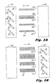
- Figures 3A through 3D are schematic plan views illustrating the nozzle firing sequence used on four successive passes of the orifice plate over a given print area. These successive passes are used to form adjacent upper and lower solid fill areas of cyan, C, and magenta, M, and these solid fill areas define a single horizontal cyan/magenta interface boundary.
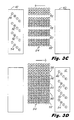
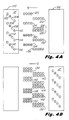
- Figures 4A through 4D are schematic plan views illustrating the nozzle firing sequence used on four successive passes of the orifice plate over a given print area to form solid fill areas of cyan, C, magenta, M, yellow, Y, and black, K, as shown in Figure 4D. These C, M, Y, and K solid fill areas are separated in Figure 4D by both vertical and horizontal interface boundaries located between the solid fill areas as shown.
- the TFR substrate 16 is in turn mounted on one surface of a pen body housing 18 having separate ink storage compartments 20, 22, 24, and 26 therein containing, respectively, the primary ink colors of cyan, magenta, yellow, and black.
- This ink storage may be accomplished using a polyurethane foam material in the compartments 20, 22, 24, and 26, and processes used for foam storage in this type of pen body housing construction are disclosed, for example, in U. S. Patent No. 4,771,295 issued to Jeffrey P. Baker et al, assigned to the present assignee and incorporated herein by reference.
- the orifice plate 12 of Figure 1 also shown in the enlarged plan view of Figure 2, includes four columns of nozzles 30, 32, 34, and 36 which are fluidically isolated one from another and fed, respectively, with the four primary ink colors of cyan, magenta, yellow, and black as indicated in these figures.
- Each of these nozzle columns is separated from an adjacent column by a width dimension W as indicated in Figure 2 and is offset vertically from an adjacent nozzle position by a length dimension D.
- the center-to-center spacing between adjacent nozzles of like color in any of the nozzle columns 30, 32, 34, and 36 is a dimension of four (4) times the number of nozzle columns, or 4D as indicated in Figure 2.
- DPI dots per inch
- W will range typically from 25D to 32D.
- the orifice plate or nozzle plate 12 is first moved as shown in Figure 3A from a first or starting position 40 on the right hand side of the figure to a second position 42 and in the direction of the arrow shown to form a dot pattern 44.
- the nozzles 46, 48, 50, 52, and 54 in the nozzle plate 12 are fired simultaneously to form, respectively, the two upper cyan dot rows 56 and 58 and the three lower magenta dot rows 60, 62, and 64 as indicated.
- the nozzle plate 12 is first moved vertically down by a distance of one dot row with respect to the print media, D, and then the nozzles 46, 50, 52, and 54 are fired simultaneously to add the dot rows 66, 68, 70, and 72, respectively, in the resulting dot pattern 74.
- FIGs 4A through 4D these figures illustrate an ink jet printing process operative in accordance with the present invention wherein four solid fill areas of cyan, magenta, yellow, and black are formed adjacent to one another and define both vertical and horizontal interface boundaries of separation therebetween.
- an orifice plate 12' is moved from the right hand position 98 in the direction of the arrow to the left hand position 100.
- the nozzles 102, 104, 106, 108, 110, 112, 114, 116, and 118 on the nozzle plate 12' are fired to form, respectively, the cyan row 120, the yellow row 122, the cyan row l4, the yellow row 126, the black row 128, the magenta row 130, the black row 132, the magenta row 134, and the black row 136.
- the cyan row 138 is formed using the cyan nozzle 102 simultaneously with the formation of the black row 140, the cyan row 142, the yellow row 144, the magenta row 146, the black row 148, the magenta row 150, and the black row 152. These latter seven rows are formed, respectively, with the firing of nozzles 104, 106, 110, 112, 114, 116, and 118 in the nozzle plate 12'.
- the solid area color fill pattern 170 shown in Figure 4D is. completed with the left-to-right printhead motion shown therein to add the completing rows 172, 174, 176, 178, 180, and 182 of the pattern 170.
- the nozzles 102, 104, 107, 110,112, 114, 116 and 118 are fired to form the two upper solid fill areas of cyan and yellow and the two lower solid fill areas of magenta and black.
- the upper blocks of cyan and yellow are separated from the lower blocks of magenta and black by a continuous horizontal C/M and Y/K color boundary and by a continuous vertical C/Y and M/K color boundary.
- the formation of these solid area color fill patterns and their associated C/M and Y/K horizontal color boundries never requires the deposition of more than two adjacent rows of dots either simultaneously or in rapid succession on a single pass of an ink jet pen. Also, it will be appreciated from the above description of Figures 4A-4D that in forming the continuous C/Y and M/K vertical color boundary, two horizontal adjacent dots of different colors are never deposited either simultaneously or in rapid succession during a single printing pass.
- the number of nozzles in each nozzle column can be increased substantially, and the size, shape, dimensions and spacing of these nozzles may be widely varied depending upon the particular ink jet printing application in which this ink jet pen is used.
- this pen may be modified for use with ink ejection transducers (e.g. piezoelectric types) other than thermal ink jet heater resistors and for use with ink storage methods other than foam storage.
- ink ejection transducers e.g. piezoelectric types
- ink storage methods other than foam storage e.g. piezoelectric types
- An example of another suitable ink storage method and pen body construction is the capillary ink feed system disclosed in U. S. Patent No. 4,791,438 issued to Gary E. Hanson et al, assigned to the present assignee and incorporated herein by reference.
- the present invention is not limited to the use of a single nozzle plate and a corresponding single ink jet pen, but instead may employ, for example, two or more side-by-side pens which have the same adjacent nozzle column relationship as is described above.
- two or more separate pens may be replaced independently of each other, and this is particularly desirable where disposable ink jet pens are used in printing applications with a large disparity in ink color demands.
- the present invention is both compatible and useful with super pixelling printing processes where dot-next-to-dot (DND) printing is used for the mixing of colors in a matrix of pixels which themselves constitute super pixels.
- DND dot-next-to-dot
- These matrices may for example be equally sectioned two-by-two or three-by-three super pixels where the divided sections of the super pixel matrix are selectively printed with different colors of ink to form a secondary color fill.
- the quadrants of a two-by-two super pixel may be selectively printed with the primary ink colors of magenta/yellow, cyan/yellow, and cyan/magenta to form the secondary colors of red, green and blue, respectively.
- the present invention teaches a novel approach to both time and spatial separation of ink drop (dot) deposition on the printed media, it may be further combined with super pixelling techniques such as those described in the above-identified Trask and Chan et al copending and coassigned applications to add even a further dimension of time and spatial separation to the ink dot deposition process. This combination serves to even further enhance the ink drying uniformity and print quality of the printed media.
Landscapes
- Engineering & Computer Science (AREA)
- Quality & Reliability (AREA)
- Ink Jet (AREA)
- Particle Formation And Scattering Control In Inkjet Printers (AREA)
Applications Claiming Priority (2)
| Application Number | Priority Date | Filing Date | Title |
|---|---|---|---|
| US45479289A | 1989-12-21 | 1989-12-21 | |
| US454792 | 1995-05-31 |
Publications (1)
| Publication Number | Publication Date |
|---|---|
| EP0433556A2 true EP0433556A2 (fr) | 1991-06-26 |
Family
ID=23806108
Family Applications (1)
| Application Number | Title | Priority Date | Filing Date |
|---|---|---|---|
| EP19900116669 Withdrawn EP0433556A2 (fr) | 1989-12-21 | 1990-08-30 | Appareil et procédé pour l'impression multicolore avec des jets d'encre |
Country Status (3)
| Country | Link |
|---|---|
| EP (1) | EP0433556A2 (fr) |
| JP (1) | JPH04118250A (fr) |
| CA (1) | CA2023022A1 (fr) |
Cited By (9)
| Publication number | Priority date | Publication date | Assignee | Title |
|---|---|---|---|---|
| EP0595657A3 (en) * | 1992-10-30 | 1994-07-20 | Canon Kk | Ink jet recording method and ink jet recording apparatus |
| EP0595651A3 (en) * | 1992-10-30 | 1994-08-24 | Canon Kk | Ink jet recording system |
| US5654744A (en) * | 1995-03-06 | 1997-08-05 | Hewlett-Packard Company | Simultaneously printing with different sections of printheads for improved print quality |
| EP0938976A1 (fr) * | 1998-02-26 | 1999-09-01 | Toshiba Tec Kabushiki Kaisha | Méthode d'actionnement d'une tête d'enregistrement |
| US6390597B1 (en) * | 1994-04-12 | 2002-05-21 | Rohm Co., Ltd. | Inkjet printing head and inkjet printer |
| DE10057061C1 (de) * | 2000-11-17 | 2002-05-23 | Koenig & Bauer Ag | Druckvorrichtung |
| EP1647401A3 (fr) * | 2001-06-06 | 2006-05-03 | Hewlett-Packard Company, A Delaware Corporation | Regroupement d'orifices d'une tête d'impression |
| US11712896B2 (en) | 2018-03-12 | 2023-08-01 | Hewlett-Packard Development Company, L.P. | Nozzle arrangements and supply channels |
| US11807005B2 (en) | 2018-03-12 | 2023-11-07 | Hewlett-Packard Development Company, L.P. | Nozzle arrangements |
Families Citing this family (11)
| Publication number | Priority date | Publication date | Assignee | Title |
|---|---|---|---|---|
| JPH10278317A (ja) | 1997-02-04 | 1998-10-20 | Seiko Epson Corp | インクジェット式記録装置 |
| EP0893265A3 (fr) | 1997-07-25 | 2000-05-10 | Seiko Epson Corporation | Dispositif d'impression par jet d'encre |
| JP2009241444A (ja) * | 2008-03-31 | 2009-10-22 | Fujifilm Corp | 液滴吐出装置及び画像形成方法 |
| JP5707805B2 (ja) * | 2010-09-15 | 2015-04-30 | 株式会社リコー | 画像形成装置 |
| JP2014004780A (ja) * | 2012-06-26 | 2014-01-16 | Riso Kagaku Corp | インクジェット印刷装置 |
| JP5654535B2 (ja) * | 2012-08-29 | 2015-01-14 | 富士フイルム株式会社 | インクジェット記録方法、及び、印刷物 |
| JP5878097B2 (ja) * | 2012-08-29 | 2016-03-08 | 富士フイルム株式会社 | インクジェット記録方法 |
| JP2014046480A (ja) * | 2012-08-29 | 2014-03-17 | Fujifilm Corp | インクジェット記録方法、及び、印刷物 |
| JP2014046479A (ja) * | 2012-08-29 | 2014-03-17 | Fujifilm Corp | インクジェット記録方法、及び、印刷物 |
| JP5964721B2 (ja) * | 2012-10-25 | 2016-08-03 | 富士フイルム株式会社 | インクジェット記録装置及びインクジェット記録方法 |
| JP6426022B2 (ja) * | 2015-02-13 | 2018-11-21 | 株式会社ミマキエンジニアリング | 液体吐出装置及び液体吐出方法 |
-
1990
- 1990-08-09 CA CA 2023022 patent/CA2023022A1/fr not_active Abandoned
- 1990-08-30 EP EP19900116669 patent/EP0433556A2/fr not_active Withdrawn
- 1990-12-21 JP JP41350590A patent/JPH04118250A/ja active Pending
Cited By (17)
| Publication number | Priority date | Publication date | Assignee | Title |
|---|---|---|---|---|
| US6086185A (en) * | 1992-10-30 | 2000-07-11 | Canon Kabushiki Kaisha | Ink jet recording method and ink jet recording apparatus |
| EP0595651A3 (en) * | 1992-10-30 | 1994-08-24 | Canon Kk | Ink jet recording system |
| US5748207A (en) * | 1992-10-30 | 1998-05-05 | Canon Kabushiki Kaisha | Ink jet recording system for preventing blurring at color boundary portion |
| EP0595657A3 (en) * | 1992-10-30 | 1994-07-20 | Canon Kk | Ink jet recording method and ink jet recording apparatus |
| EP0919387A1 (fr) * | 1992-10-30 | 1999-06-02 | Canon Kabushiki Kaisha | Procédé et appareil d'enregistrement à jet d'encre |
| US6390597B1 (en) * | 1994-04-12 | 2002-05-21 | Rohm Co., Ltd. | Inkjet printing head and inkjet printer |
| US5903290A (en) * | 1995-03-06 | 1999-05-11 | Hewlett-Packard Co. | Simultaneously printing with different sections of printheads for improved print quality |
| US5654744A (en) * | 1995-03-06 | 1997-08-05 | Hewlett-Packard Company | Simultaneously printing with different sections of printheads for improved print quality |
| EP0938976A1 (fr) * | 1998-02-26 | 1999-09-01 | Toshiba Tec Kabushiki Kaisha | Méthode d'actionnement d'une tête d'enregistrement |
| US6533379B1 (en) | 1998-02-26 | 2003-03-18 | Toshiba Tec Kabushiki Kaisha | Driving method for recording head |
| DE10057061C1 (de) * | 2000-11-17 | 2002-05-23 | Koenig & Bauer Ag | Druckvorrichtung |
| US6742867B2 (en) | 2000-11-17 | 2004-06-01 | Koenig & Bauer Aktiengesellschaft | Printing device |
| EP1647401A3 (fr) * | 2001-06-06 | 2006-05-03 | Hewlett-Packard Company, A Delaware Corporation | Regroupement d'orifices d'une tête d'impression |
| US11712896B2 (en) | 2018-03-12 | 2023-08-01 | Hewlett-Packard Development Company, L.P. | Nozzle arrangements and supply channels |
| US11807005B2 (en) | 2018-03-12 | 2023-11-07 | Hewlett-Packard Development Company, L.P. | Nozzle arrangements |
| EP3703951B1 (fr) * | 2018-03-12 | 2024-02-14 | Hewlett-Packard Development Company, L.P. | Agencements d'ajutages et canaux d'alimentation |
| US11958293B2 (en) | 2018-03-12 | 2024-04-16 | Hewlett-Packard Development Company, L.P. | Nozzle arrangements |
Also Published As
| Publication number | Publication date |
|---|---|
| CA2023022A1 (fr) | 1991-06-22 |
| JPH04118250A (ja) | 1992-04-20 |
Similar Documents
| Publication | Publication Date | Title |
|---|---|---|
| EP0433556A2 (fr) | Appareil et procédé pour l'impression multicolore avec des jets d'encre | |
| US4593295A (en) | Ink jet image recording device with pitch-shifted recording elements | |
| US6312102B1 (en) | Color ink jet recording method and apparatus using black ink and color-mixed black ink | |
| US5903290A (en) | Simultaneously printing with different sections of printheads for improved print quality | |
| EP0247179B1 (fr) | Imprimante a jet d'encre multitonalite | |
| US4855752A (en) | Method of improving dot-on-dot graphics area-fill using an ink-jet device | |
| EP0863020B1 (fr) | Procédé et dispositif pour améliorer la distribution des gouttes d'encre dans l'impression à jet d'encre | |
| US5971524A (en) | Alignment of differently sized printheads in a printer | |
| EP1085457B1 (fr) | Réduction d'effet de bande dans l'impression à passages multiples | |
| EP0420399A1 (fr) | Procédé d'impression entrelacée | |
| EP0539157B1 (fr) | Appareil d'enregistrement à jet d'encre en couleur | |
| CN101121320B (zh) | 喷墨记录头 | |
| EP1176021B1 (fr) | Système d'impression utilisant des masques d'impression à résolutions qui sont des multiples non-entiers l'une par rapport à l'autre | |
| JP3229454B2 (ja) | インクジェット記録方法およびインクジェット記録装置 | |
| JPS6256151A (ja) | 多色式インキ印字機構の印字ヘツドにおけるノズル開口 | |
| JPH10250059A (ja) | インクジェット・プリンタ用の印刷ヘッドを製造する方法及び印刷方法 | |
| EP0899681B1 (fr) | Procédé d'impression avec imprimante à jet d'encre utiliant une résolution horizontale accrue | |
| EP0517520B1 (fr) | Méthode et dispositif d'enregistrement par jet d'encre | |
| US6834936B2 (en) | Ink jet printing apparatus and ink jet printing method | |
| US6655773B2 (en) | Gray scale pattern and recording method and recording apparatus employing the gray scale pattern | |
| JPH0776160A (ja) | ドット印刷方法及びドット印刷のためのインクジェット印字ヘッド | |
| US6896356B1 (en) | Print apparatus and printing method for forming a color image by applying different color inks to a printing material using a recording head | |
| US6688716B2 (en) | Ink jet recording apparatus and method | |
| JP4046390B2 (ja) | 高精度の印刷のためのインクジェット印刷ヘッド及びその作動方法 | |
| JP2003118150A (ja) | インクジェット記録ヘッド及びインクドット記録装置 |
Legal Events
| Date | Code | Title | Description |
|---|---|---|---|
| PUAI | Public reference made under article 153(3) epc to a published international application that has entered the european phase |
Free format text: ORIGINAL CODE: 0009012 |
|
| STAA | Information on the status of an ep patent application or granted ep patent |
Free format text: STATUS: THE APPLICATION HAS BEEN WITHDRAWN |
|
| AK | Designated contracting states |
Kind code of ref document: A2 Designated state(s): DE FR GB IT |
|
| 18W | Application withdrawn |
Withdrawal date: 19910510 |