EP0433601B1 - Dispositif à genouillère hydraulique - Google Patents
Dispositif à genouillère hydraulique Download PDFInfo
- Publication number
- EP0433601B1 EP0433601B1 EP19900120066 EP90120066A EP0433601B1 EP 0433601 B1 EP0433601 B1 EP 0433601B1 EP 19900120066 EP19900120066 EP 19900120066 EP 90120066 A EP90120066 A EP 90120066A EP 0433601 B1 EP0433601 B1 EP 0433601B1
- Authority
- EP
- European Patent Office
- Prior art keywords
- toggle lever
- piston rod
- housing
- swivel
- pin
- Prior art date
- Legal status (The legal status is an assumption and is not a legal conclusion. Google has not performed a legal analysis and makes no representation as to the accuracy of the status listed.)
- Expired - Lifetime
Links
Images
Classifications
-
- B—PERFORMING OPERATIONS; TRANSPORTING
- B25—HAND TOOLS; PORTABLE POWER-DRIVEN TOOLS; MANIPULATORS
- B25B—TOOLS OR BENCH DEVICES NOT OTHERWISE PROVIDED FOR, FOR FASTENING, CONNECTING, DISENGAGING OR HOLDING
- B25B5/00—Clamps
- B25B5/06—Arrangements for positively actuating jaws
- B25B5/12—Arrangements for positively actuating jaws using toggle links
- B25B5/122—Arrangements for positively actuating jaws using toggle links with fluid drive
Definitions
- the invention relates to a pressure medium-operated toggle lever tensioning device according to the preamble of patent claim 1.
- Such a toggle lever tensioning device is previously known from DE-AS 22 22 686.
- a support plate in particular transport trolley or pallet support plate, is already known, with a clamping device for objects that can be clamped on the plate, the clamping device having a clamping lever as a connecting link between two rockers and forming a quadrilateral joint with them, with its clamping part the joint which projects above a rocker and an adjusting drive element is arranged on the four-bar linkage.
- the support plate is provided with a through-opening arranged in the adjustment path of the tensioning lever, the tensioning device being arranged under the support plate and the tensioning of the tensioning lever being in the form of a hook, the joints of the four-bar linkage being arranged in this way and the wings are dimensioned in such a way that the tensioning lever in the tensioned position extends through the passage opening with its longitudinal axis transverse to its course when the tensioning lever is reset under the support plate.
- the drive member of the four-bar linkage is designed in the form of a toggle lever drive.
- a clamping tool is known with a back and forth in guides on a support, actuated by a drive pressure block, and a clamping arm articulated via a fixed pivot on the support with an inclined operating slot extending from the movement path of the pressure block , with which the pressure block slidably cooperates in order to pivot and clamp the clamping arm.
- the actuating slot contains a first leg that is more inclined to the path of movement of the printing block, and a second leg that is inclined less to the path of movement of the printing block.
- a gripping device in which a collet is moved back and forth by a piston-cylinder unit which is acted upon alternately on both sides by pressure.
- the tensioning arm is arranged so as to be pivotable via a tab on a bolt fixed to the housing and at a distance from it by a second bolt on the housing.
- a clamping device in particular for clamping workpieces, which has a lifting cylinder with clamping iron arranged on a base plate, the lifting cylinder being pivoted at one end to the base plate, while the other end is a guide device, preferably has guide pins which are guided through fixed curved guide tracks.
- the invention has for its object to improve a toggle lever clamping device of the prerequisite type in such a way that it can also be used as a base clamp.
- this toggle lever tensioning device is made usable as a base clamp, so that the tensioning hook can be moved completely into the space of the housing in which the toggle joint arrangement is also located and which is connected to the free atmosphere.
- This tensioning hook is moved in the tightest of spaces and precisely guided by a guide. This also results in a stable articulation and guidance of the tensioning hook.
- the tensioning hook can always be moved exactly on its predetermined path without the need for many joints and link elements.
- the tensioning hook itself emerges through an opening in the upper plate of the housing if it is to be brought into the tensioned position.
- Claim 3 describes a particularly advantageous embodiment in which the housing consists in one piece of material from a casting and
- the cylinder for the toggle lever tensioning device can be integrally connected in terms of material or functionally in one piece in some other way.
- the upper plate of the casting simultaneously forms a mounting plate and can have suitable bores or holes for this, which also applies to the plate opposite this plate.
- the housing closes the toggle joint arrangement and the link support relatively dirt and dust-tight. In any case, it protects these parts from direct impact and shock loads (claim 3).
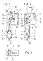
- the reference numeral 1 designates a housing-like cylinder in which a piston 2 is guided in a cylinder space 3 so as to be longitudinally displaceable and sealingly by seals (not shown).
- Pressure medium in particular air pressure, is supplied to the cylinder chamber 3 through connection channels 4 or 5, whereby the piston 2 is to be acted upon alternately on both sides with pressure medium pressure.
- a piston rod 6 is integrally connected to the piston 2 and is sealed in the region of a collar 7 by sealing means, not shown.
- the piston rod 6 exits into a movement space 8 which is connected to the free atmosphere or an ambient space via an opening 9 of large cross section.
- the movement space 8 is enclosed by a housing 10 which, in the embodiment shown, is made in one piece from cast material and is either integral with the cylinder 1 or functionally connected. The latter is not shown.
- a toggle joint arrangement 11 Arranged in the movement space 8 is a toggle joint arrangement 11, which is assigned at least one bracket 12, which is pivotally connected to the piston rod 6 via a piston rod pin 13.
- the piston rod pin 13 is arranged orthogonal to the longitudinal axis of the piston rod 6 and carries a roller 14 and 15 at each end.
- Each of the rollers 14 and 15 is guided in a guide groove 16 and 17, respectively.
- the guide grooves 16 and 17 run parallel to each other and parallel to the longitudinal axis of the piston rod 6 and are part of the housing 10 and incorporated into this.
- the piston rod pin 13 is guided in the housing 10 with relatively little friction, which also has advantages when the toggle joint arrangement 11 is driven over dead center.
- the tab 12 is pivotally coupled at its end via a stationary toggle joint axis 18 to a rocker 19 which is arranged in the housing 10 so as to be pivotable about an axis 20 fixed to the housing.
- a two-armed lever 21 is pivotally connected to the axis 18, which is arranged pivotably in the direction C or D and which can be pivoted completely into the movement space 8 from the tensioned position from FIG. 1 into the release position according to FIG. 2.
- the two-armed lever 21 is guided by a pivot pin 22 in a link slot 23, the longitudinal axis of which extends approximately at 45 ° to the longitudinal axis of the piston rod 6.
- the pivot pin 22 can be provided at its ends with at least one roller for low-friction guidance.
- the link slot 23 can only be provided on one side of the housing 10. However, it is also possible to arrange the link slots in pairs on opposite sides of the housing and to guide the pivot pin 22 at its opposite end through a roller in the associated link slot.
- an end stop is arranged, which is adjustable by a screw 25.
- inductive proximity switches or the like can also be assigned to the piston 2. It is also possible to change the shape of the two-armed lever 21 as required. As can be seen, the two-armed lever 21 describes a relatively narrow circular arc, so that it is arranged in a protected manner in the movement space 8 in the release position.
- the upper plate 26 can be provided with one or more bores for fastening the toggle lever tensioning device, although this is not shown. This also applies to the side plate 27 and the base plate 28.
Landscapes
- Engineering & Computer Science (AREA)
- Mechanical Engineering (AREA)
- Clamps And Clips (AREA)
- Transmission Devices (AREA)
- Jigs For Machine Tools (AREA)
Claims (5)
- Dispositif à genouillère hydraulique, en particulier pour pièces de carrosserie, comprenant1.1 Un carter monobloc ou en plusieurs pièces (1, 10) comprenant un compartiment cylindrique (3) dans lequel se déplace le piston (2) et un compartiment (8) dans lequel se meut la bielle (6) du piston et le mécanisme d'articulation de la genouillère (11);1.2 Des moyens, à l'extrémité libre du piston, servant au guidage de la bielle et guidés dans des rainures (16, 17) ménagées dans le carter (10), et un axe de bielle;1.3 Une patte montée pivotante sur l'axe (13) de la bielle et sur l'axe (18) d'articulation de la genouillère; 1.4 Un levier de serrage (21) à deux bras, dont l'extrémitémotrice est également fixée sur l'axe (18) d'articulation de la genouillère et dont l'extrémité libre sert également de pièce de serrage,1.5 Un axe pivotant (22) s'appuyant contre le carter (1, 10) et pénétrant dans le levier de serrage, caractérisé en ce que1.6 L'axe pivotant (22) est guidé dans une fente-coulisse (23) du carter (10),1.7 Une bielle (19) fixée pivotante dans le carter (10) est fixée par son autre extrémité également à l'axe (18) d'articulation de la genouillère.
- Dispositif à genouillère hydraulique selon revendication 1, caractérisé en ce qu'à un axe pivotant (22) est affecté au moins un galet grâce auquel l'axe pivotant (22) est guidé dans une fente-guide (23), ce dernier (22) coupant en angle aigu l'axe longitudinal de la bielle (6) du piston.
- Dispositif à genouillère hydraulique selon la/les revendication(s) 1 et/ou 2, caractérisé en ce que le carter (10) est matériellement constitué de fonte monobloc et présente, sur une plaque supérieure (26) et/ou sur une plaque latérale (27) et/ou sur une plaque de fond (28), des perçages de fixation et/ou des vis et des trous taraudés de montage.
- Dispositif à genouillère hydraulique selon revendication 1 ou l'une des revendications suivantes, caractérisé en ce que le compartiment (8) présente une ouverture (9) dans le carter (10) et que traverse le levier de serrage (21), ce pourquoi la pièce constitutive du levier de serrage (21) a la forme d'un crochet et son mouvement de serrage est de sens opposé au mouvement de la bielle.
- Dispositif à genouillère hydraulique selon revendication 1 ou l'une des revendications suivantes, caractérisé en ce qu'une patte (12) du mécanisme d'articulation de la genouillère (11) est reliée, basculante autour d'un axe (20) solidaire du carter, à la bielle (19) via un axe indéplaçable (18) de l'articulation de genouillère et dont (18) le tracé est parallèle à l'axe (13) de la bielle du piston, dont (20) l'axe longitudinal de basculement a un tracé parallèle à l'axe (13) de la bielle du piston et à l'axe (18) d'articulation de la genouillère.
Applications Claiming Priority (2)
| Application Number | Priority Date | Filing Date | Title |
|---|---|---|---|
| DE19893938208 DE3938208C1 (fr) | 1989-11-17 | 1989-11-17 | |
| DE3938208 | 1989-11-17 |
Publications (3)
| Publication Number | Publication Date |
|---|---|
| EP0433601A2 EP0433601A2 (fr) | 1991-06-26 |
| EP0433601A3 EP0433601A3 (en) | 1992-02-26 |
| EP0433601B1 true EP0433601B1 (fr) | 1994-06-08 |
Family
ID=6393702
Family Applications (1)
| Application Number | Title | Priority Date | Filing Date |
|---|---|---|---|
| EP19900120066 Expired - Lifetime EP0433601B1 (fr) | 1989-11-17 | 1990-10-19 | Dispositif à genouillère hydraulique |
Country Status (3)
| Country | Link |
|---|---|
| EP (1) | EP0433601B1 (fr) |
| DE (1) | DE3938208C1 (fr) |
| ES (1) | ES2055272T3 (fr) |
Cited By (1)
| Publication number | Priority date | Publication date | Assignee | Title |
|---|---|---|---|---|
| CN110315371A (zh) * | 2019-07-31 | 2019-10-11 | 中冶华天工程技术有限公司 | 一种钢板桩(h型钢)锯切自动侧夹紧装置 |
Families Citing this family (17)
| Publication number | Priority date | Publication date | Assignee | Title |
|---|---|---|---|---|
| DE9412722U1 (de) | 1994-08-06 | 1994-09-29 | DE-STA-CO Metallerzeugnisse GmbH, 61449 Steinbach | Kniehebelspannvorrichtung |
| DE29519232U1 (de) * | 1995-12-05 | 1996-04-04 | Tünkers Maschinenbau GmbH, 40880 Ratingen | Kniehebelspannvorrichtung |
| DE19715452C1 (de) * | 1997-04-10 | 1998-09-24 | Mannesmann Ag | Spannvorrichtung zum Halten oder Verfahren von flachen Werkstücken |
| DE29718643U1 (de) * | 1997-10-21 | 1997-12-11 | Tünkers Maschinenbau GmbH, 40880 Ratingen | Druckmittelbetätigbare kombinierte Zentrier- und Spannvorrichtung, insbesondere zur Verwendung im Karosseriebau der Kfz-Industrie |
| DE69805497T2 (de) * | 1998-02-18 | 2003-01-16 | Delaware Capital Formation, Inc. | Geschlossene pneumatische Spannvorrichtung |
| DE102004040606B3 (de) * | 2004-08-21 | 2006-01-12 | Tünkers Maschinenbau Gmbh | Als Gripper ausgebildete Kniehebelspannvorrichtung, insbesondere zur Verwendung im Karosseriebau der Kfz-Industrie |
| ITTO20080914A1 (it) * | 2008-12-09 | 2010-06-10 | Vep Automation Srl | Dispositivo d'aggancio di pezzi, particolarmente di fogli di lamiera |
| DE202011106409U1 (de) | 2011-09-29 | 2011-11-22 | Hohenstein Vorrichtungsbau Und Spannsysteme Gmbh | Spannkassette mit Niederzugspanner |
| CN102658484A (zh) * | 2012-04-25 | 2012-09-12 | 浙江宏源车轮有限公司 | 工程车无内胎车轮气门孔专用夹具 |
| CN106903630B (zh) * | 2017-04-27 | 2019-03-01 | 苏州赛腾精密电子股份有限公司 | 一种平行夹紧机构 |
| CN108942030B (zh) * | 2018-06-23 | 2020-10-02 | 刘道灵 | 一种气动单向拉紧勾销装置 |
| CN108994128A (zh) * | 2018-08-01 | 2018-12-14 | 浙江金瑞五金索具有限公司 | 一种弹簧钩扳弯机 |
| CN109227175A (zh) * | 2018-11-15 | 2019-01-18 | 宁波市慈力金属制品有限公司 | 一种用于毂盖端面车削的工装夹具 |
| DE102020003577B3 (de) * | 2020-06-16 | 2021-06-10 | Olaf und André Tünkers GbR (vertretungsberechtigter Gesellschafter: Dipl.-Ing. Olaf Tünkers, 40883 Ratingen) | Unterbodenspanner mit Kniehebelgelenk und Kulissenführung, zur Verwendung im Karosseriebau der Kfz-lndustrie |
| CN115502906A (zh) * | 2022-08-22 | 2022-12-23 | 中国北方发动机研究所(天津) | 一种多用途夹具 |
| US12576792B2 (en) | 2022-11-30 | 2026-03-17 | Rivian Ip Holdings, Llc | Clamp mechanism |
| CN118110391A (zh) * | 2022-11-30 | 2024-05-31 | 瑞维安知识产权控股有限责任公司 | 闩锁机构 |
Family Cites Families (11)
| Publication number | Priority date | Publication date | Assignee | Title |
|---|---|---|---|---|
| DD60527A (fr) * | ||||
| US2995794A (en) * | 1959-07-20 | 1961-08-15 | Hacking Vernon Edward | Toggle clamp |
| US3480271A (en) * | 1967-10-18 | 1969-11-25 | Gen Motors Corp | Toggle clamp |
| FR1568574A (fr) * | 1968-05-31 | 1969-05-23 | ||
| US3565415A (en) * | 1968-07-05 | 1971-02-23 | Leland F Blatt | Power-operated bar clamp |
| US3570835A (en) * | 1968-10-08 | 1971-03-16 | Dover Corp | Power operated clamping device |
| US3545050A (en) * | 1969-01-30 | 1970-12-08 | I S I Mfg Inc | Power clamp with pull-back action |
| FR2157696B3 (fr) * | 1971-10-26 | 1974-06-07 | Maac Ets | |
| DE2222686B2 (de) * | 1972-05-09 | 1980-06-12 | Tuenkers Maschinenbau Gmbh, 4030 Ratingen | Druckmittelbetatigte Kniehebelspannvorrichtung, insbesondere für Karosserieteile |
| DE2457933A1 (de) * | 1974-12-07 | 1976-06-16 | Schuler Gmbh L | Schnellspannvorrichtung fuer pressen |
| DE3419878C1 (de) * | 1984-05-28 | 1985-12-19 | De-Sta-Co Metallerzeugnisse Gmbh, 6000 Frankfurt | Tragplatte insbesondere Transportwagen- od. Palettentragplatte mit Spannvorrichtung |
-
1989
- 1989-11-17 DE DE19893938208 patent/DE3938208C1/de not_active Expired - Lifetime
-
1990
- 1990-10-19 ES ES90120066T patent/ES2055272T3/es not_active Expired - Lifetime
- 1990-10-19 EP EP19900120066 patent/EP0433601B1/fr not_active Expired - Lifetime
Cited By (1)
| Publication number | Priority date | Publication date | Assignee | Title |
|---|---|---|---|---|
| CN110315371A (zh) * | 2019-07-31 | 2019-10-11 | 中冶华天工程技术有限公司 | 一种钢板桩(h型钢)锯切自动侧夹紧装置 |
Also Published As
| Publication number | Publication date |
|---|---|
| EP0433601A2 (fr) | 1991-06-26 |
| DE3938208C1 (fr) | 1990-11-22 |
| ES2055272T3 (es) | 1994-08-16 |
| EP0433601A3 (en) | 1992-02-26 |
Similar Documents
| Publication | Publication Date | Title |
|---|---|---|
| EP0433601B1 (fr) | Dispositif à genouillère hydraulique | |
| DE3419878C1 (de) | Tragplatte insbesondere Transportwagen- od. Palettentragplatte mit Spannvorrichtung | |
| EP0999911A1 (fr) | Dispositif pour la separation par rupture de la barre et du chapeau d'une bielle | |
| DE4313473C2 (de) | Schließeinheit für eine Spritzgießmaschine | |
| DD244723A5 (de) | Presse mit einer oberen und einer unteren platte zum aufspannen eines werkzeugpaketes | |
| DE69805747T2 (de) | Spannvorrichtung für eine holmlose Spritzgiessmaschine | |
| DE1479547B2 (de) | Vorrichtung zum gleichzeitigen Entfernen überflüssiger· Abfallabschnitte von mehreren fertig geformten Kunststoffteilen, insbesondere von nach dem Blasverfahren hergestellten Hohlkörpern | |
| DE3331676C2 (de) | Formspannvorrichtung | |
| DE29615157U1 (de) | Kniehebelspann- und Greifvorrichtung | |
| EP1824641B1 (fr) | Element de serrage de pieces, notamment un etau | |
| DE19705049C1 (de) | Schließeinheit für eine Zwei-Platten-Spritzgießmaschine | |
| EP0107763B1 (fr) | Etau, en particulier pour machine-outil | |
| DE3831378C2 (de) | Anschlagvorrichtung für Tischsägen | |
| DE3329942C1 (de) | Spannvorrichtung für insbes. spanabhebend zu bearbeitende Werkstücke | |
| DE3221834A1 (de) | Schienenzange | |
| DE1502860A1 (de) | Werkzeugmaschine mit einer Einspannvorrichtung fuer das Werkstueck | |
| DE19535436C1 (de) | Holmlose Formschließeinrichtung für eine Spritzgießmaschine | |
| DE7614577U1 (de) | Naehmaschine zum zusammennaehen der teile eines textilen arbeitsstueckes | |
| DE19847973C1 (de) | Vorschubeinrichtung zum schrittweisen Werkstücktransport in Produktionsmaschinen | |
| DE29621358U1 (de) | Linearmodul | |
| DE2443376A1 (de) | Presse, insbesondere rahmenpresse | |
| DE20303751U1 (de) | Schubstangenspanner, insbesondere zur Verwendung im Kfz-Bau der Karosserieindustrie | |
| DE29822135U1 (de) | Als Handspanner ausgebildete Kniehebelspannvorrichtung, insbesondere zur Verwendung im Karosseriebau der Kfz-Industrie | |
| DE1477299A1 (de) | Schneidwerkzeug zum Bearbeiten von Metall | |
| DE3400813C2 (fr) |
Legal Events
| Date | Code | Title | Description |
|---|---|---|---|
| PUAI | Public reference made under article 153(3) epc to a published international application that has entered the european phase |
Free format text: ORIGINAL CODE: 0009012 |
|
| 17P | Request for examination filed |
Effective date: 19901106 |
|
| AK | Designated contracting states |
Kind code of ref document: A2 Designated state(s): ES FR IT |
|
| PUAL | Search report despatched |
Free format text: ORIGINAL CODE: 0009013 |
|
| AK | Designated contracting states |
Kind code of ref document: A3 Designated state(s): ES FR IT |
|
| 17Q | First examination report despatched |
Effective date: 19930210 |
|
| GRAA | (expected) grant |
Free format text: ORIGINAL CODE: 0009210 |
|
| ITF | It: translation for a ep patent filed | ||
| AK | Designated contracting states |
Kind code of ref document: B1 Designated state(s): ES FR IT |
|
| REG | Reference to a national code |
Ref country code: ES Ref legal event code: FG2A Ref document number: 2055272 Country of ref document: ES Kind code of ref document: T3 |
|
| ET | Fr: translation filed | ||
| PLBE | No opposition filed within time limit |
Free format text: ORIGINAL CODE: 0009261 |
|
| STAA | Information on the status of an ep patent application or granted ep patent |
Free format text: STATUS: NO OPPOSITION FILED WITHIN TIME LIMIT |
|
| 26N | No opposition filed | ||
| PGFP | Annual fee paid to national office [announced via postgrant information from national office to epo] |
Ref country code: ES Payment date: 20091117 Year of fee payment: 20 |
|
| PGFP | Annual fee paid to national office [announced via postgrant information from national office to epo] |
Ref country code: FR Payment date: 20091029 Year of fee payment: 20 Ref country code: IT Payment date: 20091015 Year of fee payment: 20 |
|
| REG | Reference to a national code |
Ref country code: ES Ref legal event code: FD2A Effective date: 20120423 |
|
| PG25 | Lapsed in a contracting state [announced via postgrant information from national office to epo] |
Ref country code: ES Free format text: LAPSE BECAUSE OF EXPIRATION OF PROTECTION Effective date: 20101020 |