EP0433649A1 - Pompe doseuse pour fluides - Google Patents
Pompe doseuse pour fluides Download PDFInfo
- Publication number
- EP0433649A1 EP0433649A1 EP19900121666 EP90121666A EP0433649A1 EP 0433649 A1 EP0433649 A1 EP 0433649A1 EP 19900121666 EP19900121666 EP 19900121666 EP 90121666 A EP90121666 A EP 90121666A EP 0433649 A1 EP0433649 A1 EP 0433649A1
- Authority
- EP
- European Patent Office
- Prior art keywords
- metering pump
- pump according
- shaped
- seat
- constituted
- Prior art date
- Legal status (The legal status is an assumption and is not a legal conclusion. Google has not performed a legal analysis and makes no representation as to the accuracy of the status listed.)
- Withdrawn
Links
Images


Classifications
-
- F—MECHANICAL ENGINEERING; LIGHTING; HEATING; WEAPONS; BLASTING
- F04—POSITIVE - DISPLACEMENT MACHINES FOR LIQUIDS; PUMPS FOR LIQUIDS OR ELASTIC FLUIDS
- F04B—POSITIVE-DISPLACEMENT MACHINES FOR LIQUIDS; PUMPS
- F04B53/00—Component parts, details or accessories not provided for in, or of interest apart from, groups F04B1/00 - F04B23/00 or F04B39/00 - F04B47/00
- F04B53/10—Valves; Arrangement of valves
- F04B53/1037—Flap valves
- F04B53/1047—Flap valves the valve being formed by one or more flexible elements
- F04B53/106—Flap valves the valve being formed by one or more flexible elements the valve being a membrane
- F04B53/1067—Flap valves the valve being formed by one or more flexible elements the valve being a membrane fixed at its whole periphery and with an opening at its centre
-
- F—MECHANICAL ENGINEERING; LIGHTING; HEATING; WEAPONS; BLASTING
- F04—POSITIVE - DISPLACEMENT MACHINES FOR LIQUIDS; PUMPS FOR LIQUIDS OR ELASTIC FLUIDS
- F04B—POSITIVE-DISPLACEMENT MACHINES FOR LIQUIDS; PUMPS
- F04B13/00—Pumps specially modified to deliver fixed or variable measured quantities
-
- F—MECHANICAL ENGINEERING; LIGHTING; HEATING; WEAPONS; BLASTING
- F04—POSITIVE - DISPLACEMENT MACHINES FOR LIQUIDS; PUMPS FOR LIQUIDS OR ELASTIC FLUIDS
- F04B—POSITIVE-DISPLACEMENT MACHINES FOR LIQUIDS; PUMPS
- F04B17/00—Pumps characterised by combination with, or adaptation to, specific driving engines or motors
- F04B17/03—Pumps characterised by combination with, or adaptation to, specific driving engines or motors driven by electric motors
-
- F—MECHANICAL ENGINEERING; LIGHTING; HEATING; WEAPONS; BLASTING
- F04—POSITIVE - DISPLACEMENT MACHINES FOR LIQUIDS; PUMPS FOR LIQUIDS OR ELASTIC FLUIDS
- F04B—POSITIVE-DISPLACEMENT MACHINES FOR LIQUIDS; PUMPS
- F04B53/00—Component parts, details or accessories not provided for in, or of interest apart from, groups F04B1/00 - F04B23/00 or F04B39/00 - F04B47/00
- F04B53/10—Valves; Arrangement of valves
- F04B53/1037—Flap valves
- F04B53/1047—Flap valves the valve being formed by one or more flexible elements
- F04B53/1052—Flap valves the valve being formed by one or more flexible elements two flexible elements oscillating around a fixed point
-
- F—MECHANICAL ENGINEERING; LIGHTING; HEATING; WEAPONS; BLASTING
- F04—POSITIVE - DISPLACEMENT MACHINES FOR LIQUIDS; PUMPS FOR LIQUIDS OR ELASTIC FLUIDS
- F04B—POSITIVE-DISPLACEMENT MACHINES FOR LIQUIDS; PUMPS
- F04B53/00—Component parts, details or accessories not provided for in, or of interest apart from, groups F04B1/00 - F04B23/00 or F04B39/00 - F04B47/00
- F04B53/10—Valves; Arrangement of valves
- F04B53/109—Valves; Arrangement of valves inlet and outlet valve forming one unit
- F04B53/1092—Valves; Arrangement of valves inlet and outlet valve forming one unit and one single element forming both the inlet and outlet closure member
-
- F—MECHANICAL ENGINEERING; LIGHTING; HEATING; WEAPONS; BLASTING
- F04—POSITIVE - DISPLACEMENT MACHINES FOR LIQUIDS; PUMPS FOR LIQUIDS OR ELASTIC FLUIDS
- F04B—POSITIVE-DISPLACEMENT MACHINES FOR LIQUIDS; PUMPS
- F04B9/00—Piston machines or pumps characterised by the driving or driven means to or from their working members
- F04B9/02—Piston machines or pumps characterised by the driving or driven means to or from their working members the means being mechanical
-
- F—MECHANICAL ENGINEERING; LIGHTING; HEATING; WEAPONS; BLASTING
- F16—ENGINEERING ELEMENTS AND UNITS; GENERAL MEASURES FOR PRODUCING AND MAINTAINING EFFECTIVE FUNCTIONING OF MACHINES OR INSTALLATIONS; THERMAL INSULATION IN GENERAL
- F16K—VALVES; TAPS; COCKS; ACTUATING-FLOATS; DEVICES FOR VENTING OR AERATING
- F16K15/00—Check valves
- F16K15/14—Check valves with flexible valve members
- F16K15/1402—Check valves with flexible valve members having an integral flexible member cooperating with a plurality of seating surfaces
-
- H—ELECTRICITY
- H02—GENERATION; CONVERSION OR DISTRIBUTION OF ELECTRIC POWER
- H02K—DYNAMO-ELECTRIC MACHINES
- H02K21/00—Synchronous motors having permanent magnets; Synchronous generators having permanent magnets
- H02K21/12—Synchronous motors having permanent magnets; Synchronous generators having permanent magnets with stationary armatures and rotating magnets
- H02K21/14—Synchronous motors having permanent magnets; Synchronous generators having permanent magnets with stationary armatures and rotating magnets with magnets rotating within the armatures
- H02K21/18—Synchronous motors having permanent magnets; Synchronous generators having permanent magnets with stationary armatures and rotating magnets with magnets rotating within the armatures having horse-shoe armature cores
- H02K21/185—Synchronous motors having permanent magnets; Synchronous generators having permanent magnets with stationary armatures and rotating magnets with magnets rotating within the armatures having horse-shoe armature cores with the axis of the rotor perpendicular to the plane of the armature
-
- H—ELECTRICITY
- H02—GENERATION; CONVERSION OR DISTRIBUTION OF ELECTRIC POWER
- H02K—DYNAMO-ELECTRIC MACHINES
- H02K7/00—Arrangements for handling mechanical energy structurally associated with dynamo-electric machines, e.g. structural association with mechanical driving motors or auxiliary dynamo-electric machines
- H02K7/10—Structural association with clutches, brakes, gears, pulleys or mechanical starters
- H02K7/118—Structural association with clutches, brakes, gears, pulleys or mechanical starters with starting devices
-
- Y—GENERAL TAGGING OF NEW TECHNOLOGICAL DEVELOPMENTS; GENERAL TAGGING OF CROSS-SECTIONAL TECHNOLOGIES SPANNING OVER SEVERAL SECTIONS OF THE IPC; TECHNICAL SUBJECTS COVERED BY FORMER USPC CROSS-REFERENCE ART COLLECTIONS [XRACs] AND DIGESTS
- Y10—TECHNICAL SUBJECTS COVERED BY FORMER USPC
- Y10T—TECHNICAL SUBJECTS COVERED BY FORMER US CLASSIFICATION
- Y10T137/00—Fluid handling
- Y10T137/7722—Line condition change responsive valves
- Y10T137/7837—Direct response valves [i.e., check valve type]
- Y10T137/7838—Plural
- Y10T137/7843—Integral resilient member forms plural valves
-
- Y—GENERAL TAGGING OF NEW TECHNOLOGICAL DEVELOPMENTS; GENERAL TAGGING OF CROSS-SECTIONAL TECHNOLOGIES SPANNING OVER SEVERAL SECTIONS OF THE IPC; TECHNICAL SUBJECTS COVERED BY FORMER USPC CROSS-REFERENCE ART COLLECTIONS [XRACs] AND DIGESTS
- Y10—TECHNICAL SUBJECTS COVERED BY FORMER USPC
- Y10T—TECHNICAL SUBJECTS COVERED BY FORMER US CLASSIFICATION
- Y10T137/00—Fluid handling
- Y10T137/7722—Line condition change responsive valves
- Y10T137/7837—Direct response valves [i.e., check valve type]
- Y10T137/7879—Resilient material valve
- Y10T137/7888—With valve member flexing about securement
Definitions
- the present invention relates to a fluid metering pump.
- washing machines are currently provided with devices for metering the powder detergent during the various washing steps which are absolutely unsuitable for being used with liquid detergent.
- Said metering devices are in fact generally constituted by small compartments into which the powder detergent is poured; the detergent is gradually dissolved by a current of water which is caused to flow, when required, in said compartments.
- a dose of liquid detergent poured into said compartments would end up completely inside the washing containers upon the first flow of the water current.
- Dosage containers to be inserted inside the washing tumbler, among the washing, are currently used for the dosage of liquid detergents.
- Said dosage containers have an appropriate opening out of which the detergent flows during the washing cycle.
- the aim of the present invention is to provide a pump which can meter preset amounts of fluids for preset periods of time.
- a consequent primary object is to provide a fluid metering pump which can be conveniently installed in washing machines for the dosage of liquid detergents.
- Another important object is to provide a metering pump which can also be installed in other household appliances, such as for example dishwashers or others.
- Still another object is to provide a pump which can perform an extremely precise metering.
- Another object is to provide a pump which is compact and small so that it can be installed without problems in small spaces.
- Still another object is to provide a pump which requires low energy consumption for its actuation.
- Not least object is to provide a pump which can be manufactured at low cost with conventional production facilities.
- a fluid metering pump which is characterized in that it comprises a synchronous electric motor which is suitable for transmitting rotary motion to speed reduction means which are associated, by virtue of means suitable for converting rotary motion into reciprocating motion, with a piston element which is slidable in a hollow body in which it defines a variable-volume chamber which is associated with value means for the intake and discharge of fluid.
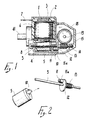
- the first embodiment of the fluid metering pump comprises a body 1, advantageously made of plastic material, which internally defines a first chamber 2, in which the stator pack 3 of a permanent-magnet synchronous motor is embedded in epoxy resin, and a second cylindrical chamber 4, which is separate from said first chamber and in which the rotor 5 of said motor is accommodated.
- Two Faston connectors 7 for connection to the electric mains extend out of the resin-embedded region from said stator pack 3, which is approximately provided with electric windings 6.
- Said second chamber 4 has an open end and an end provided with an axial seat 8 for the insertion of a corresponding end of a metallic shaft 9 which supports said rotor 5 so that it is free to rotate about its longitudinal axis.
- Said rotor 5 has, at the region of the open end of said second chamber 4, a substantially radial tab 10 which is suitable for rotationally entraining a corresponding cylindrical tab 11 which is annularly embraced by a shock-absorbing rubber element 11a and extends eccentrically from a disk-like element 12 which is advantageously axially monolithic with a worm screw 13 which is advantageously made of plastic material and is rigidly associated with the shaft 9, the second end whereof is inserted in a seat 14 which is defined inside a housing or casing 15, also advantageously made of plastic material, which is fixed to the body 1 with screws which are not illustrated in the figures.
- Said shaft 9 is appropriately free to rotate in its end seats 8 and 14.
- Two parallel walls 16 and 17 extend inside said housing 15, and a gearwheel 18 is rotationally coupled therebetween and meshes with said worm screw 13.
- Said gearwheel 18 is advantageously monolithic with its own rotation pivots 19 and 20, the second of which has a considerably larger diameter than the first and has an eccentric tab 21 with an articulation pivot 22 for the end of a connecting rod 23 the opposite end whereof is advantageously monolithic with a pivot 24 which is rotatably coupled between the walls of a piston 25 which is also made of plastic material and is slidable in a hollow body 26 which is advantageously monolithic with said body 1, in which it defines a variable-volume chamber 27.
- Said piston 25 which conveniently has a cylindrical extension, is provided, on its outer surface, with an annular groove in which a sealing O-ring 28 is accommodated.
- Said hollow body 26 widens at the top of said chamber 27 and forms an insertion seat for an intermediate element 29 and a cover 30 which is externally associated with an O-ring 31 which is suitable for ensuring the seal on said hollow body 26.
- Said cover 30 is advantageously associated with the body 26 by means of snap-together couplings 32.
- the intermediate element 29 and the cover 30 are longitudinally traversed by ducts 33 and 34 for the passage of fluid, and corresponding seats for intake and discharge valves, respectively 35 and 36, are defined therein.
- Each of said valves 35 and 36 which are conveniently arranged in opposite positions, is constituted by a mushroom-shaped element, respectively 37 and 38, with a conical head accommodated in a complementary shaped seat, and by a cylindrical helical spring, respectively 39 and 40, which is suitable for biasing the head against the corresponding seat.
- Said cover is completed by two connections 41 and 42 which allow to connect it to a hydraulic circuit.
- the rotation of the permanent-magnet motor causes the rotation of the shaft 9 which supports the worm screw 13 which meshes with the gearwheel 18.
- the worm screw 13 and the gearwheel 18 perform a considerable speed reduction and transmit the motion to the connecting rod 23 by means of the articulation pivot 22.
- the articulation pivot 22 and the connecting rod 23 convert the rotary motion into the reciprocating motion of the piston 25, the stroke whereof in the direction suitable for increasing the volume of the chamber 27 causes a compression of the spring 39 and the intake of liquid through the mushroom-shaped element 27, whereas a stroke in the direction suitable for reducing the volume of the chamber 27 causes the drawn fluid to press on the mushroom-shaped element 38 and on the spring 40, allowing the discharge of said fluid.
- the permanent-magnet motor is a synchronous electric motor, its rotation rate is fixed and preset, for a constant mains frequency, by the number of polar expansions.
- a second embodiment of the fluid metering pump comprises a body 101 advantageously made of plastic material which is shaped so as to internally define a first chamber 102 in which the stator pack 103 of a permanent-magnet synchronous electric motor is embedded in epoxy resin.
- Said body 101 again defines a second chamber 104 which is separate from the first one 102, has a cylindrical extension and internally accommodates the rotor 105 of said motor.
- Said stator pack 103 has electric windings 106 from which two Faston connectors 107 for connection to the electric mains extend.
- said second chamber 104 has an open end and an end which is provided with an axial seat 108 for the insertion of a corresponding end of an advantageously metallic shaft 109 which supports said rotor 105 so that it is free to rotate about its longitudinal axis.
- Said rotor 105 has, at the region of the open end of said second chamber 104, a substantially radial tub 110 and an axial bush 111 which resets head-on on a corresponding axial bush 112 which has the same diameter and extends axially from a bell-shaped element 113 which is advantageously axially monolithic with a worm screw 114 advantageously made of plastic material.
- Said worm screw 114 is freely associated with the shaft 109, the second end whereof is inserted in a seat 115 which is defined inside a housing 116, again advantageously made of plastic material, which is fixed to the body 101.
- Said axial bushes 111 and 112 are externally embraced by a cylindrical helical metallic spring 117 the ends whereof extend in a radial direction; a first end 118 is in lateral contact with said tab 110 and a second end 119 is inserted in a slot or hole 120 which is present on said bell-shaped element 113.
- Two parallel walls 121 and 122 extend from said body 101 and, by cooperating with similar parallel walls 123 and 124 which extend inside the housing 116, are suitable for supporting, in a rotationally coupled manner, a gearwheel 125 which meshes with said worm screw 114.
- Said gearwheel 125 is advantageously monolithic with its rotation pivots 126 and 127, the first of which, considerably smaller in diameter than the second one, is inserted in a bearing 128 which is externally provided with annular raised portions 129 which block its axial sliding with respect to the supporting walls.
- Said bearing 128 advantageously rests, with one of its annular raised portions 130, in a respective annular seat 131 which is defined laterally on said gearwheel 125.
- the second rotation pivot 127 has an eccentric tab 132 with an articulation pivot 133 for the end of a connecting rod 134 the opposite end whereof is advantageously monolithic with a pivot 135 which is rotationally coupled between the walls of a piston 136, again advantageously made of plastic material, which is slidable in a hollow body 137 which is advantageously monolithic with said body 101.
- Said piston 136 which conveniently has a cylindrical extension, defines a variable-volume chamber 138 inside the hollow body 137 and has, on its outer surface, an annular groove in which a sealing O-ring 139 is accommodated.
- Said hollow body 137 expands at the head of said chamber 138 and forms a seat 140 for the insertion of the valve system of the pump.
- Said valve system comprises a first insert 141 in which two fluid passages of appropriate shape, respectively 142 and 143, are defined.
- An intermediate element 144 is furthermore inserted in said seat 140 and a cover 145 is associated within the seat 140 of the hollow body 137 for example by means of snap-together couplings 146.
- the intermediate element 144 and the cover 145 are longitudinally traversed by fluid passage ducts 147 and 148, and corresponding seats for intake and discharge valves, respectively 149 and 150, are defined therein.
- a gasket 151 is interposed between the intermediate element 144 and the cover 145 and is shaped so as to be in contact both with their surfaces and with the lateral surface of the seat 140, so as to prevent any internal recirculation of fluid as well as any outward escape thereof.
- said gasket 151 is appropriately shaped like a figure-eight and has a small circumferential raised portion 152 to be accommodated in a complementarily shaped annular recess of said seat 140.
- the compression performed by the cover 145 upon closure also causes the outward expansion of the gasket 151 and of its raised portion 152, producing a seal.
- Each of said valves 149 and 150 which are appropriately arranged in opposite positions, is constituted by a mushroom-shaped element, respectively 153 and 154, with a conical head accommodated in a complementarily shaped seat, and by a cylindrical helical spring, respectively 155 and 156, which is suitable for biasing the head against the corresponding seat.
- Said cover 145 is completed by two connections 157 and 158 which allow to connect it to a hydraulic circuit.
- valve system of the pump can be constituted by two internally hollow elements, respectively an intermediate element 244 and a cover 245, which are again accommodated in an adapted seat at the head of the variable-volume chamber 138 and are longitudinally traversed by fluid passage ducts 246 and 247.
- Said elements 244 and 245 have corresponding seats of valves 248 and 249 defined between them; said valves are preferably constituted by balls made of rubber or of a similar material which are monolithic by virtue of supporting spokes, respectively 250 and 251, which connect them to a sealing element 252 substantially in the shape of a figure-eight which is interposed between the intermediate element 244 and the cover 245.
- Sealing seats 253 and 254 of the valves 248 and 249 are conveniently arranged in opposite positions, and said spokes 250 and 251 constitute elastic elements which maintain the closure of the fluid passages.
- Said cover 245 is completed by two connections 255 and 256 which allow to connect it to a hydraulic circuit.
- said spring 117 regardless of the angular position of the tab 110 when the rotor 105 starts, by making contact with said tab exerts a thrust which causes its loading and therefore an elastic thrust in the opposite direction which is sufficient to give the motor such a torque as to move the worm screw 114 and therefore the entire pump.
- the presence of the bearing 128 further facilitates the rotation of the gearwheel 125 and reduces losses due to friction thereof.
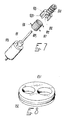
- a third embodiment of the fluid metering pump according to the invention is generally indicated by the reference numeral 301 and comprises a piston 302 to which a pivot 303 is articulated; said pivot is arranged at the end of a connecting rod 304 of a connecting rod-crank kinematic system which actuates it.
- Said connecting rod-crank kinematic system is in turn associated with a gearmotor unit similar to the previous one which is not illustrated and has a permanent-magnet synchronous motor.
- Said piston 302 which conveniently has a cylindrical extension, is slidable in a hollow body 306 in which it defines a variable-volume chamber 307, and has, on its outer surface, an annular groove in which a sealing ring 308, for example an O-ring, is accommodated.
- a head 310 is fixed on said hollow body 306, for example by means of screws, with the interposition of a sealing ring 309, and supports a valve 311 which has both an intake function and a discharge function.
- said valve 311 which is conveniently made of rubber or of an equivalent material, has an umbrella-like shape and has a tubular body 312 which is inserted in a complementarily shaped axial seat 313 of the head 310 and is connected to the outside by means of an also axial connection 314.
- Said tubular body 312 is fixed to the seat 313 due to the insertion of a complementarily shaped raised portion 316 which extends from the seat 313 in an annular recess 315 with which said tubular body is provided.
- said tubular body 312 has a beak-shaped nozzle 317 which extends toward the connection 314 and has elastically deformable sealing lips which define or close a rectilinear passage slit.
- the perimetric lip of the hood 318 of said valve 311 is elastically deformable and rests on a planar surface 319 which is deformed on the head 310 at the outlet of the seat 313.
- Said seat 313 is surrounded by an annular chamber 320 which is connected to the outside by means of a connection 321 and to the inside by means of an annular chamber 322 which is formed between the hood 318 and the surface 319.
- the operation of the third embodiment of the pump according to the invention is as follows: the reciprocating motion of the piston 302 alternately causes a suction effect and a pumping effect; the first effect causes the closing deformation of the lips of the hood 318 which causes the fluid to enter through the connection 321, whereas the second effect causes the opening deformation of the lips of the nozzle 317, which cause the fluid drawn into the chamber 307 to escape through the slit defined thereby and through the connection 314.
- a single valve therefore performs the dual function of intake valve and discharge valve.
- the pump is in fact extremely compact and is advantageously mostly made of elements manufactured by injection-molding thermoplastic materials.
- the assembly of the various elements is performed with conventional production facilities.
- the materials employed, as well as the dimensions, may be any according to the requirements.
Landscapes
- Engineering & Computer Science (AREA)
- General Engineering & Computer Science (AREA)
- Mechanical Engineering (AREA)
- Power Engineering (AREA)
- Details Of Reciprocating Pumps (AREA)
Applications Claiming Priority (4)
| Application Number | Priority Date | Filing Date | Title |
|---|---|---|---|
| IT04174889A IT1236619B (it) | 1989-11-17 | 1989-11-17 | Pompa dosatrice di fluidi |
| IT4174889 | 1989-11-17 | ||
| IT4160090 | 1990-05-14 | ||
| IT41600A IT1238937B (it) | 1990-05-14 | 1990-05-14 | Pompa perfezionata per il dosaggio di fluidi |
Publications (1)
| Publication Number | Publication Date |
|---|---|
| EP0433649A1 true EP0433649A1 (fr) | 1991-06-26 |
Family
ID=26329134
Family Applications (1)
| Application Number | Title | Priority Date | Filing Date |
|---|---|---|---|
| EP19900121666 Withdrawn EP0433649A1 (fr) | 1989-11-17 | 1990-11-13 | Pompe doseuse pour fluides |
Country Status (2)
| Country | Link |
|---|---|
| US (1) | US5088902A (fr) |
| EP (1) | EP0433649A1 (fr) |
Cited By (15)
| Publication number | Priority date | Publication date | Assignee | Title |
|---|---|---|---|---|
| DE9200243U1 (de) * | 1992-01-11 | 1992-03-12 | Wolter, Hans, 8941 Sontheim | Dosierpumpe für Flüssigkeiten |
| DE4424257A1 (de) * | 1994-07-09 | 1996-01-18 | Aweco Kunststofftech Geraete | Zentrifugalpumpe hoher Leistung mit Einphasensynchronmotorantrieb |
| WO2004029454A1 (fr) * | 2002-09-26 | 2004-04-08 | Fluid Management Inc. | Pompe doseuse et ensemble soupapes equipant ladite pompe |
| WO2005015019A1 (fr) * | 2003-07-17 | 2005-02-17 | Cooper Cameron Corporation | Systeme de pompe pour commande hydraulique d'une soupape |
| US7934376B2 (en) | 2005-04-27 | 2011-05-03 | Cameron International Corporation | Hydraulic actuation assembly |
| GB2497816A (en) * | 2011-12-22 | 2013-06-26 | Hsu Chih-Kao | Water pump driven by AC synchronous motor |
| CN103174619A (zh) * | 2013-04-02 | 2013-06-26 | 合肥日上电器有限公司 | 往复注射式计量泵 |
| US9074445B2 (en) | 2009-03-27 | 2015-07-07 | Onesubsea Ip Uk Limited | DC powered subsea inverter |
| EP2829650A4 (fr) * | 2012-03-22 | 2015-12-09 | Wuxi Little Swan Co Ltd | Machine à laver et ensemble pompe de distribution de détergent de celle-ci |
| EP3026267A1 (fr) * | 2014-11-25 | 2016-06-01 | HILTI Aktiengesellschaft | Pompe, en particulier destinée à doser la distribution d'un fluide |
| EP3022441A4 (fr) * | 2013-07-17 | 2017-04-12 | SharkNinja Operating LLC | Ensemble pompe mécanique à débit variable |
| CN106762507A (zh) * | 2016-12-20 | 2017-05-31 | 郑州航空工业管理学院 | 具有多级可变供油传动比及多运行模式的节能柴油机 |
| US10018009B2 (en) | 2015-02-26 | 2018-07-10 | Cameron International Corporation | Locking apparatus |
| IT201800009423A1 (it) * | 2018-10-12 | 2020-04-12 | Romaco Srl | Dispositivo e apparecchiatura per l’erogazione di quantità dosate di un materiale liquido |
| CN114215714A (zh) * | 2022-01-05 | 2022-03-22 | 多普医疗科技(郑州)有限公司 | 一种流体输送计量系统及流体输送装置 |
Families Citing this family (20)
| Publication number | Priority date | Publication date | Assignee | Title |
|---|---|---|---|---|
| IT1246925B (it) * | 1991-04-04 | 1994-11-29 | Ricerca Elettromeccanica Srl | Metodo per la produzione di parti di motori elettrici e motori utilizzanti parti prodotte con detto metodo |
| IT1259848B (it) * | 1992-11-27 | 1996-03-28 | Hydor Srl | Motore elettrico sincrono, particolarmente per pompe immergibili e pompa incorporante tale motore |
| US5600953A (en) * | 1994-09-28 | 1997-02-11 | Aisin Seiki Kabushiki Kaisha | Compressed air control apparatus |
| US6135719A (en) * | 1997-12-29 | 2000-10-24 | Oilquip, Inc. | Method and apparatus for metering injection pump flow |
| US6135724A (en) * | 1998-07-08 | 2000-10-24 | Oilquip, Inc. | Method and apparatus for metering multiple injection pump flow |
| DE19860573A1 (de) * | 1998-12-29 | 2000-07-06 | Eberspaecher J Gmbh & Co | Brennstoffdosierpumpe für ein Heizgerät, insbesondere für einen Zuheizer oder eine Standheizung eines Kraftfahrzeuges |
| AU760775B2 (en) * | 1999-06-15 | 2003-05-22 | Lg Electronics Inc. | Method for controlling drain motor |
| AU749296B2 (en) | 1999-06-15 | 2002-06-20 | Lg Electronics Inc. | Device and method for controlling drain motor |
| US7011469B2 (en) * | 2001-02-07 | 2006-03-14 | R. Sanderson Management, Inc. | Piston joint |
| US7331271B2 (en) | 2001-02-08 | 2008-02-19 | R. Sanderson Management, Inc. | Variable stroke/clearance mechanism |
| US6913447B2 (en) | 2002-01-22 | 2005-07-05 | R. Sanderson Management, Inc. | Metering pump with varying piston cylinders, and with independently adjustable piston strokes |
| WO2003100231A1 (fr) * | 2002-05-28 | 2003-12-04 | R. Sanderson Management, Inc. | Mecanisme de protection contre les surcharges |
| BRPI0511592A (pt) * | 2004-05-26 | 2008-01-02 | Sanderson R Man Inc | mecanismo de curso e folga variáveis |
| CN100385125C (zh) * | 2005-01-10 | 2008-04-30 | 胡世璇 | 高精度液压同步比例分流集流器 |
| TWI438342B (zh) * | 2006-07-28 | 2014-05-21 | Lot Vacuum Co Ltd | 具有魯式與螺旋轉子之複合型乾式真空幫浦 |
| US7708031B2 (en) * | 2006-11-13 | 2010-05-04 | International Business Machines Corporation | Check valve |
| US7942652B1 (en) * | 2008-11-29 | 2011-05-17 | Murray Lawrence D | Bi-directional centripetally-powered reciprocating pump |
| KR20120004208A (ko) * | 2010-07-06 | 2012-01-12 | 삼성전자주식회사 | 세제공급장치 및 이를 가지는 세탁기 |
| DE102014002955A1 (de) * | 2013-03-19 | 2014-09-25 | Marquardt Mechatronik Gmbh | Dosierpumpe |
| US20250027493A1 (en) * | 2023-07-20 | 2025-01-23 | Dongguan Shengzai Electronic Technology Co., Ltd. | Pump body assembly and booster energy-saving water pump with the same |
Citations (7)
| Publication number | Priority date | Publication date | Assignee | Title |
|---|---|---|---|---|
| US1907110A (en) * | 1930-12-20 | 1933-05-02 | Hobart Bros Company | Car washing pump |
| US3855129A (en) * | 1972-03-06 | 1974-12-17 | Waters Associates Inc | Novel pumping apparatus |
| US4108167A (en) * | 1977-01-31 | 1978-08-22 | Teledyne Industries, Inc. | Dental syringe |
| GB2024528A (en) * | 1978-06-02 | 1980-01-09 | Askoll Srl | Centrifugal pump for small throughputs particularly for water circulation in aquariums and the like |
| EP0207430A2 (fr) * | 1985-07-01 | 1987-01-07 | EASTHORPE INVESTMENTS Ltd. | Pompe centrifuge |
| EP0223643A1 (fr) * | 1985-10-04 | 1987-05-27 | DOSAPRO MILTON ROY, SociÀ©té dite: | Procédé pour établir de manière précise le débit d'une pompe doseuse et pompe doseuse faisant application |
| DE3630088A1 (de) * | 1986-09-04 | 1988-03-17 | Bosch Gmbh Robert | Stelleinrichtung |
Family Cites Families (10)
| Publication number | Priority date | Publication date | Assignee | Title |
|---|---|---|---|---|
| FR588113A (fr) * | 1924-08-29 | 1925-04-30 | Compresseur à faible encombrement et commande directe | |
| US2260180A (en) * | 1937-07-19 | 1941-10-21 | John H Herder | Constant pressure diaphragm pump |
| US3131646A (en) * | 1962-10-15 | 1964-05-05 | Parco Products Co | Hand pump |
| US3416557A (en) * | 1964-04-29 | 1968-12-17 | Union Tank Car Co | Check valve with wiping action |
| US3664774A (en) * | 1970-05-05 | 1972-05-23 | Dexter Automatic Products Co I | Primer pump |
| US3730217A (en) * | 1971-05-19 | 1973-05-01 | Gen Motors Corp | Check valve |
| US4422831A (en) * | 1981-11-02 | 1983-12-27 | Bender Machine Works, Inc. | Pump |
| US4614479A (en) * | 1984-04-19 | 1986-09-30 | Jackson Liu | Adjustable automatically controlled pneumatic pump device |
| FR2581707B1 (fr) * | 1985-05-10 | 1987-06-26 | Tecnoma | Perfectionnement aux pompes a membranes |
| GB8624620D0 (en) * | 1986-10-14 | 1986-11-19 | Scholl Inc | Fluid dispenser |
-
1990
- 1990-11-13 EP EP19900121666 patent/EP0433649A1/fr not_active Withdrawn
- 1990-11-14 US US07/612,378 patent/US5088902A/en not_active Expired - Lifetime
Patent Citations (8)
| Publication number | Priority date | Publication date | Assignee | Title |
|---|---|---|---|---|
| US1907110A (en) * | 1930-12-20 | 1933-05-02 | Hobart Bros Company | Car washing pump |
| US3855129A (en) * | 1972-03-06 | 1974-12-17 | Waters Associates Inc | Novel pumping apparatus |
| US3855129B1 (fr) * | 1972-03-06 | 1985-10-08 | ||
| US4108167A (en) * | 1977-01-31 | 1978-08-22 | Teledyne Industries, Inc. | Dental syringe |
| GB2024528A (en) * | 1978-06-02 | 1980-01-09 | Askoll Srl | Centrifugal pump for small throughputs particularly for water circulation in aquariums and the like |
| EP0207430A2 (fr) * | 1985-07-01 | 1987-01-07 | EASTHORPE INVESTMENTS Ltd. | Pompe centrifuge |
| EP0223643A1 (fr) * | 1985-10-04 | 1987-05-27 | DOSAPRO MILTON ROY, SociÀ©té dite: | Procédé pour établir de manière précise le débit d'une pompe doseuse et pompe doseuse faisant application |
| DE3630088A1 (de) * | 1986-09-04 | 1988-03-17 | Bosch Gmbh Robert | Stelleinrichtung |
Cited By (24)
| Publication number | Priority date | Publication date | Assignee | Title |
|---|---|---|---|---|
| DE9200243U1 (de) * | 1992-01-11 | 1992-03-12 | Wolter, Hans, 8941 Sontheim | Dosierpumpe für Flüssigkeiten |
| DE4424257A1 (de) * | 1994-07-09 | 1996-01-18 | Aweco Kunststofftech Geraete | Zentrifugalpumpe hoher Leistung mit Einphasensynchronmotorantrieb |
| DE4424257C2 (de) * | 1994-07-09 | 1999-03-18 | Aweco Kunststofftech Geraete | Zentrifugalpumpe hoher Leistung mit Einphasensynchronmotorantrieb |
| WO2004029454A1 (fr) * | 2002-09-26 | 2004-04-08 | Fluid Management Inc. | Pompe doseuse et ensemble soupapes equipant ladite pompe |
| WO2005015019A1 (fr) * | 2003-07-17 | 2005-02-17 | Cooper Cameron Corporation | Systeme de pompe pour commande hydraulique d'une soupape |
| GB2419645A (en) * | 2003-07-17 | 2006-05-03 | Cooper Cameron Corp | Pump device for the hydraulic actuation of a valve |
| GB2419645B (en) * | 2003-07-17 | 2008-07-02 | Cooper Cameron Corp | Pump device for the hydraulic actuation of a valve |
| US8770950B2 (en) | 2003-07-17 | 2014-07-08 | Cameron International Corporation | Pump device for the hydraulic actuation of a valve |
| US7934376B2 (en) | 2005-04-27 | 2011-05-03 | Cameron International Corporation | Hydraulic actuation assembly |
| US9074445B2 (en) | 2009-03-27 | 2015-07-07 | Onesubsea Ip Uk Limited | DC powered subsea inverter |
| GB2497816A (en) * | 2011-12-22 | 2013-06-26 | Hsu Chih-Kao | Water pump driven by AC synchronous motor |
| EP2829650A4 (fr) * | 2012-03-22 | 2015-12-09 | Wuxi Little Swan Co Ltd | Machine à laver et ensemble pompe de distribution de détergent de celle-ci |
| EP2829649A4 (fr) * | 2012-03-22 | 2016-02-17 | Wuxi Little Swan Co Ltd | Dispositif de dosage pouvant s'adapter aux variations de viscosité de détergent et son procédé de contrôle |
| CN103174619A (zh) * | 2013-04-02 | 2013-06-26 | 合肥日上电器有限公司 | 往复注射式计量泵 |
| EP3022441A4 (fr) * | 2013-07-17 | 2017-04-12 | SharkNinja Operating LLC | Ensemble pompe mécanique à débit variable |
| US10932644B2 (en) | 2013-07-17 | 2021-03-02 | Sharkninja Operating Llc | Variable flow rate mechanical pump assembly |
| US11401928B2 (en) | 2013-07-17 | 2022-08-02 | Sharkninja Operating Llc | Variable flow rate mechanical pump assembly |
| EP3026267A1 (fr) * | 2014-11-25 | 2016-06-01 | HILTI Aktiengesellschaft | Pompe, en particulier destinée à doser la distribution d'un fluide |
| US10018009B2 (en) | 2015-02-26 | 2018-07-10 | Cameron International Corporation | Locking apparatus |
| CN106762507A (zh) * | 2016-12-20 | 2017-05-31 | 郑州航空工业管理学院 | 具有多级可变供油传动比及多运行模式的节能柴油机 |
| CN106762507B (zh) * | 2016-12-20 | 2018-07-10 | 郑州航空工业管理学院 | 具有多级可变供油传动比及多运行模式的节能柴油机 |
| IT201800009423A1 (it) * | 2018-10-12 | 2020-04-12 | Romaco Srl | Dispositivo e apparecchiatura per l’erogazione di quantità dosate di un materiale liquido |
| CN114215714A (zh) * | 2022-01-05 | 2022-03-22 | 多普医疗科技(郑州)有限公司 | 一种流体输送计量系统及流体输送装置 |
| CN114215714B (zh) * | 2022-01-05 | 2024-05-03 | 多普医疗科技(郑州)有限公司 | 一种流体输送计量系统及流体输送装置 |
Also Published As
| Publication number | Publication date |
|---|---|
| US5088902A (en) | 1992-02-18 |
Similar Documents
| Publication | Publication Date | Title |
|---|---|---|
| US5088902A (en) | Piston type metering pump | |
| CN105473868B (zh) | 泵 | |
| US8926275B2 (en) | Centrifugal pump | |
| CA2167356A1 (fr) | Dispositif de demarrage pour le rotor d'un moteur synchrone a aimant permanent | |
| US7347005B2 (en) | Ventilation system for household appliances in particular for washing machines | |
| CN105422472B (zh) | 吸水泵 | |
| CN217696271U (zh) | 一种排浆阀及食品加工机 | |
| CN119287633B (zh) | 一种降噪的洗衣机排水泵及其降噪方法 | |
| CN114073479A (zh) | 洗碗机排水装置及洗碗机 | |
| JP2022539613A (ja) | 洗浄機器 | |
| KR20070108530A (ko) | 단-방향 동기 모터를 가진 양-방향 공기 흐름 댐퍼 | |
| CN217105356U (zh) | 一种淋浴器及其清洁剂添加组件 | |
| KR20220046837A (ko) | 세탁기용 세제자동투입장치 | |
| CN214273900U (zh) | 微型流体泵及压力流体应用设备 | |
| CN214258974U (zh) | 一种通水限温器组件及液体容器 | |
| JPH03284293A (ja) | 洗剤自動投入装置 | |
| CN115726160B (zh) | 一种添加剂投放装置及洗衣机 | |
| CN105515231A (zh) | 一种一体式水泵 | |
| CN116084140A (zh) | 一种洗涤组件及衣物处理装置 | |
| CN224173068U (zh) | 一种洗衣机的自动投放装置 | |
| JP2003106275A (ja) | 容積形ポンプ | |
| CN216036176U (zh) | 一种泡沫泵径向腔体驱动结构及泡沫泵 | |
| KR200189636Y1 (ko) | 진공펌프의 편심구조 | |
| CN209826609U (zh) | 加液双泵、液体投放系统、洗衣机和洗碗机 | |
| CN218666780U (zh) | 一种自动投放组件及洗涤设备 |
Legal Events
| Date | Code | Title | Description |
|---|---|---|---|
| PUAI | Public reference made under article 153(3) epc to a published international application that has entered the european phase |
Free format text: ORIGINAL CODE: 0009012 |
|
| AK | Designated contracting states |
Kind code of ref document: A1 Designated state(s): AT BE CH DE DK ES FR GB GR IT LI LU NL SE |
|
| 17P | Request for examination filed |
Effective date: 19911004 |
|
| STAA | Information on the status of an ep patent application or granted ep patent |
Free format text: STATUS: THE APPLICATION IS DEEMED TO BE WITHDRAWN |
|
| 18D | Application deemed to be withdrawn |
Effective date: 19930602 |