EP0433671A2 - Steuergerät der Kraftstoffeinspritzung mit Korrektion in Abhängigkeit des atmosphärischen Aussendrucks - Google Patents
Steuergerät der Kraftstoffeinspritzung mit Korrektion in Abhängigkeit des atmosphärischen Aussendrucks Download PDFInfo
- Publication number
- EP0433671A2 EP0433671A2 EP90121975A EP90121975A EP0433671A2 EP 0433671 A2 EP0433671 A2 EP 0433671A2 EP 90121975 A EP90121975 A EP 90121975A EP 90121975 A EP90121975 A EP 90121975A EP 0433671 A2 EP0433671 A2 EP 0433671A2
- Authority
- EP
- European Patent Office
- Prior art keywords
- value
- engine
- fuel injection
- transient
- accordance
- Prior art date
- Legal status (The legal status is an assumption and is not a legal conclusion. Google has not performed a legal analysis and makes no representation as to the accuracy of the status listed.)
- Granted
Links
Images
Classifications
-
- F—MECHANICAL ENGINEERING; LIGHTING; HEATING; WEAPONS; BLASTING
- F02—COMBUSTION ENGINES; HOT-GAS OR COMBUSTION-PRODUCT ENGINE PLANTS
- F02D—CONTROLLING COMBUSTION ENGINES
- F02D41/00—Electrical control of supply of combustible mixture or its constituents
- F02D41/30—Controlling fuel injection
- F02D41/32—Controlling fuel injection of the low pressure type
-
- F—MECHANICAL ENGINEERING; LIGHTING; HEATING; WEAPONS; BLASTING
- F02—COMBUSTION ENGINES; HOT-GAS OR COMBUSTION-PRODUCT ENGINE PLANTS
- F02D—CONTROLLING COMBUSTION ENGINES
- F02D41/00—Electrical control of supply of combustible mixture or its constituents
- F02D41/02—Circuit arrangements for generating control signals
- F02D41/04—Introducing corrections for particular operating conditions
- F02D41/045—Detection of accelerating or decelerating state
-
- F—MECHANICAL ENGINEERING; LIGHTING; HEATING; WEAPONS; BLASTING
- F02—COMBUSTION ENGINES; HOT-GAS OR COMBUSTION-PRODUCT ENGINE PLANTS
- F02D—CONTROLLING COMBUSTION ENGINES
- F02D41/00—Electrical control of supply of combustible mixture or its constituents
- F02D41/02—Circuit arrangements for generating control signals
- F02D41/04—Introducing corrections for particular operating conditions
- F02D41/10—Introducing corrections for particular operating conditions for acceleration
- F02D41/107—Introducing corrections for particular operating conditions for acceleration and deceleration
-
- F—MECHANICAL ENGINEERING; LIGHTING; HEATING; WEAPONS; BLASTING
- F02—COMBUSTION ENGINES; HOT-GAS OR COMBUSTION-PRODUCT ENGINE PLANTS
- F02D—CONTROLLING COMBUSTION ENGINES
- F02D2200/00—Input parameters for engine control
- F02D2200/70—Input parameters for engine control said parameters being related to the vehicle exterior
- F02D2200/703—Atmospheric pressure
Definitions
- the present invention relates to an apparatus for controlling a fuel injection quantity supplied to an engine, and in particular for making a load correction of the fuel injection quantity at a transient time.
- An air fuel ratio differs between normal and transient driving conditions due to a fact that mutual relation between a quantity of fuel deposited on the inner wall of an intake manifold and an evaporation quantity of fuel deposited thereon.
- an apparatus for controlling a fuel injection quantity for an internal combustion engine which corrects a reference fuel injection quantity set based on a quantity of intake air sucked into an internal combustion engine by using a transient correction value to be set in response to each transient condition of the engine (for example, JP-B-64-6333).
- a mass flow type apparatus for controlling a quantity of fuel injection into an internal combustion engine
- an intake air quantity is detected by means of an air flow meter and the like and a reference fuel injection quantity is set depending upon the detected intake air quantity.
- the reference fuel injection quantity becomes excessive, because air density decreases at a higher altitude place as compared with a lower altitude place.
- an atmosphere correction system for decreasing the rference fuel injection quantity with a decrease in the atmospheric pressure has been proposed.
- a speed density type system for controlling a fuel injection quantity of an internal combustion engine
- intake air pressure in an intake pipe downstream of a throttle valve is detected by using a pressure sensor and thereby an intake air quantity is determined indirectly from the detected intake pipe pressure, and then a reference fuel injection quantity is set depending upon the determined intake air quantity.
- a speed density type system since atmospheric pressure becomes lower at a higher altitude place as compared with a lower altitude place and accordingly the intake air quantity is increased at a higher altitude place even with the same intake pipe pressure, the reference fuel injection quantity becomes too small at a higher altitude place.
- an atmosphere correction system which increases and corrects the reference fuel injection quantity with a decrease in atmospheric pressure, has been proposed.
- the atmosphere correction in the fuel injection quantity control apparatuses for an internal combustion engine of the mass flow type and of the speed density type aims to correct an error of a detected intake air quantity. Even with such atmosphere correction, it is not possible to correct the deviation of an air fuel ratio due to the fact that the mutual relation between the deposition and evaporation of fuel in an intake manifold varies also with a change of atmospheric pressure, even if such an atmosphere correction is carried out.
- the present invention was made in order to solve the above mentioned problems.
- the present invention provides a fuel injection quantity control apparatus for controlling a quantity of fuel injected into an internal combustion engine, comprising means 60 for detecting atmospheric pressure, means 51 for detecting a load condition of an internal combustion engine 1, means 52 for setting a reference fuel injection quantity (t) in accordance with the load condition of the engine 1, means 53 for detecting a transient condition of said engine 1, means 54 for setting a transient correction value ⁇ T in accordance with the transient conditions of the engine 1, transient correction value correcting means 55 for correcting the transient correction value ⁇ T to be decreased as the atmospheric pressure decreases, and means 56 for setting a quantity of injection fuel TAU supplied to said engine 1 in accordance with the set value of the reference fuel injection quantity (t) and the corrected transient correction value ⁇ T.
- the transient correction value setting means 54 and the transient correction value correcting means 55 means for setting a filter value in accordance with an operation condition of the engine 1 and filtering means for filtering the reference fuel injection quantity (t) by using the filter value to detect a filtering function value may be used, and furthermore, means 54 for setting the transient correction value ⁇ T in accordance with a deviation between the reference fuel injection quantity (t) and the filtering function value may be used, and next, means 55 for correcting the set transient correction value ⁇ T in accordance with the operating condition of the engine 1 may be used.
- the reference fuel injection quantity (t) is set by the reference fuel injection quantity setting means 52 in accordance with a load condition of the engine 1 detected by the load condition detecting means 51.
- the transient correction value (K) is set by the transient correction value correcting means 55 in accordance with the atmospheric pressure PA detected by the atmospheric pressure detecting means 50.
- the transient correction value ( ⁇ T) is then set by the transient correction value setting means 54 in accordance with a transient operating condition of the engine 1 detected by the transient condition detecting means 53 and the transient correction value (K).
- the fuel injection quantity (TAU) is set by the fuel injection quantity setting means 56 in accordance with the reference fuel injection quantity (t) and the transient correction value ⁇ T.
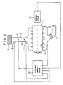
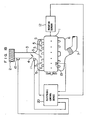
- Fig. 2 is a schematic view showing the structure of an engine and an electronic control system for the engine to which the present invention is applied.
- the engine 1 is, for example, a four stroke cycle spark ignition type engine. Combustion air is admitted to cylinders via an air cleaner 2, an intake pipe 3, and a throttle valve 4. Fuel is supplied to each cylinder via a single common injector 5 from a fuel supply path (not shown).
- SPI single point injection
- MPI multipoint injection
- An intake air temperature sensor 10 which detects the temperature of the combustion air THQ (intake air temperature) for outputting an analog voltage corresponding to the intake air temperature (THQ) and an intake air pressure sensor 11 which detects the intake air pressure PM downstream of the throttle valve for outputting an analog voltage corresponding to the intake air pressure PM are disposed on the side of the intake pipe 3.
- a thermistor type cooling water temperature sensor 13 which detects the cooling water temperature THW for outputting an analog voltage (an analog detection signal) corresponding to the cooling water temperature THW is disposed on the engine 1.
- a rotation sensor 12 detects the rotation of a crank shaft of the engine and outputs pulse signals at a frequency corresponding to the engine rotation for determining an engine rotational speed NE.
- an ignition coil for an ignition device (not shown) may be used as the rotation sensor 12. In this case, it will suffice to use ignition pulse signals from a primary terminal of the ignition coil as the rotation signal.
- An electronic control device 20 comprises a circuit which calculates the fuel injection quantity, etc. based on the detection signals from various sensors through 13 for adjusting the fuel injection quantity, for example, by controlling the period of time during which a valve of the injector 5 for injecting fuel is opened.
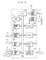
- FIG. 3 is a view showing the structure of the electronic control device 20.
- a reference numeral 100 denotes a microprocessor (CPU) which calculates the fuel injection quantity, etc.
- Reference numeral 100 denotes a rotational number counter which counts the rotational number of the engine 1 in response to signals from the rotation sensor 12.
- the rotational number counter 101 feeds an interruption command signal to an interruption control unit 102 in synchronization with the rotation of the engine.
- the interruption control unit 102 receives this signal, it outputs an interruption signal to the CPU 100 via a common bus 150.
- a digital input port 103 transmits to the CPU 100 digital signals such as a starting signal from a starter switch 14 which is turned on or off in response to the operation of a starter (not shown).
- An analog input port 104 comprising an analog multiplexer and an A/D converter has a function to effect analog-to-digital conversion of respective signals from the intake air temperature sensor 10, the intake air pressure sensor 11 and the cooling water temperature sensor 13 and to make the CPU 100 sequentially read the signals. Output information from each of units 101, 102, 103 and 104 is transmitted to the CPU 100 via the common bus 150.
- a power source circuit 105 supplies electric power to a memory unit (RAM) 107 which will be described hereafter.
- the power source circuit 105 is directly connected with a battery 17 bypassing a key switch 18. Accordingly, electric power is constantly supplied to the RAM 107 independently of the key switch 18.
- Reference numeral 106 denotes a power source circuit which is connected with the battery 17 via the key switch 18.
- the power source circuit 106 supplies electric power to units other than the RAM 107.
- the RAM 107 is a temporal memory unit which is temporarily used in the execution of a program. Since, the RAM 107 is always connected with the power source independently of the key switch 18, the contents stored in the RAM 107 will not be erased even if the operation of the engine 1 is stopped. Accordingly, RAM 107 forms an involatile memory.
- a read-only memory (ROM) stores programs and various constants.
- a fuel injection time control counter 109 having a register is formed of a down counter.
- the counter 109 converts a digital signal representative of a valve opening time of the injector 5, that is, the fuel injection quantity calculated by the CPU to a pulse signal having a pulse width (injection pulse width Ti) providing an actual opening time of the valve of the injector 5.
- Reference numeral 110 denotes a power amplifier which outputs a driving signal for driving the injector 5, and reference numeral 110 denotes a timer for measuring elapsed time to transmit it to the CPU 100.
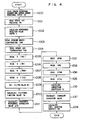
- the engine rotational number from the rotational number counter 101 is read in response to the rotation interruption signal from the interrupt control unit 102 and the engine rotational speed NE is obtained therefrom at step 1000.
- the intake air pressure PM is read through the analog input port 104 at step 1001.
- the cooling water temperature THW is read through the analog input port 104 at step 1003. Similarily, the intake air temperature THQ is read through the analog input port 104 at step 1004.
- Steps 1005 through 1017 form a routine for setting a correction value ⁇ T at a transient time.
- This transient correction value ⁇ T is set based on a difference (a transient reference correction value ⁇ T0) between the reference fuel injection pulse width (t) and a filtering function value T N which is obtained by filtering the reference fuel injection pulse width (t) in accordance with a formula (1) shown below, as is well known.
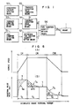
- the relation between the reference fuel injection pulse width (t) and the filtering function value T N under each operation condition is shown in Fig. 5 in which the abscissa indicates the accumulated engine rotational number.
- Areas I, II and III (hatched portions) in respective three engine operation periods DI, DII and DIII denote transient reference correction values ⁇ T0.
- T c denotes correction periods.
- Steps 1005 through 1009 form a routine for setting the filter value N T .
- the filter value N T is set so that the correction period T c corresponds to each engine operating condition (the intake air pressure PM, engine rotational speed NE, cooling water temperature THW, intake air temperature THQ, etc.).
- the filter correction value N(PM) correctponding to the intake air pressure PM is read at step 1005.
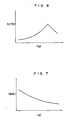
- the intake air pressure filter value N(PM) has a characteristic that it increases as the intake air pressure PM increases, as shown in Fig. 6.
- the intake air pressure filter value N(PM) decreases as the intake air pressure PM increases, as far as the intake air pressure PM is not less than a given value, as this range is shown in Fig. 6. This is due to a fact that a high load increase is applied to the fuel injection quantity TAU in this range as will be described later, and accordingly the intake air pressure filter quantity N(PM) is set so that it does not affect the correction period T c .
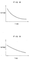
- the engine rotational speed filter value N(NE) corresponding to the engine rotational speed NE is read at a subsequent step 1006.
- the engine rotational speed filter value N(NE) has a characteristic that the engine rotational speed filter value N(NE) decreases as the engine rotational speed NE increases.
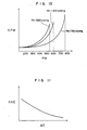
- a cooling water temperature filter value N(THW) corresponding to the cooling water temperature THW is read at step 1007.
- the cooling water temperature filter value N(THW) has a tendency that it decreases as the cooling water temperature THW increases, as shown in Fig. 8.
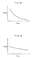
- An intake air temperature value N(THQ) corresponding to the intake air temperature THQ is read at step 1008.
- the intake air temperature filter value N(THQ) has a tendency that it decreases as the intake air temperature THQ increases as shown in Fig. 9.
- a filter amount N T is set in accordance with the following formula at step 1009 based on the filter values N(PM), N(NE), N(THW) and N(THQ) which have been read at the above-mentioned steps 1005 through 1008.
- NT N(PM) + N(NE) + N(THW) + N(THQ)
- Steps 1012 through 1016 form a routine for setting a correction factor (K) for the transient reference correction value ⁇ T0 in accordance with the engine conditions.
- K correction factor
- a load correction coefficient KPM corresponding to the intake air pressure PM is determined at step 1012. Since the intake air PM is used in place of the load, the intake air pressure PM differs with a change of the atmospheric pressure PA even if the load condition is the same. Accordingly, the load correction coefficient KPM exhibits a characteristic which is determined by the atmospheric pressure PA and the intake air pressure PM, as shown in Fig. 10.
- load correction coefficients KPM are preliminarily stored in the ROM 108 forming a two-dimensional map of the intake air pressure PM and the atmospheric pressure PA and then the coefficients KPM are read from the two-dimensional map.
- the relation between the intake air pressure PM and the local correction coefficient KPM when the atmospheric pressure is 760, 600 and 550 mmHg, as shown in Fig. 10, is stored in ROM 108 in the present embodiment.
- the coefficient is calculated from the stored values in the ROM 108 by a known interpolation, if the atmospheric pressure PA assumes intermediate values between 760 and 600 mmHg or between 600 and 550 mmHg.
- An atmospheric pressure sensor may be provided to detect the atmospheric pressure PA.
- An engine rotational speed correction coefficient KNE corresponding to the engine rotational speed NE is read at next step 1013.
- the engine rotational speed correction coefficient KNE tends to decrease with an increase in the engine rotational speed NE, as shown in Fig. 11.
- the cooling water temperature correction coefficient KTHW corresponding to the cooling water temperature THW is read at step 1014.
- the cooling water temperature correction coefficient KTHW tends to decrease with an increase in the cooling water temperature THW, as shown in Fig. 12.
- the intake air temperature correction coefficient KTHQ correcponding to the intake air temperature THQ is read at step 1015.
- the intake air correction coefficient KTHQ tends to decrease with an increase in the intake air temperature THQ, as shown in Fig. 13.
- Digital signals having an injection pulse width Ti corresponding to the fuel injection amount TAU, which has been set as mentioned above, are outputted to the injector 5.
- the load correction coefficient KPM is set in accordance with the intake air pressure PM and the atmospheric pressure PA. Accordingly, the load correction coefficient KPm is set in accordance with the load, even if the atmospheric pressure PA varies. Therefore, fuel is supplied at a rate appropriate to the load even when the atmospheric pressure PA is low. Hence, the controllability of the engine under a transient condition can be enhanced.
- the load correction coefficients KPM are preliminarily stored in the ROM 108 so that the ROM forms a two-dimensional map of the intake air pressure PM and the atmospheric pressure PA, and the coefficient KPM is read from this two-dimensional map.
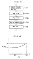
- the load correction coefficient KPM may be set as will be described below. Another embodiment of the setting of the load correction coefficient KPM will be described with reference to a flow chart shown in Fig. 14.
- a load correction reference coefficient K(PM′) in accordance with a deviation between the atmospheric pressure PA and the intake air pressure PM is read at step 1012a.
- the characteristic of the load correction reference coefficient K(PM′) corresponds to that of a given atmospheric pressure (for example, 760 mmHg in the present embodiment) among the characteristics shown in Fig. 10.
- the load correction reference coefficient K(PM′) corresponding to the corrected intake air pressure PM′ is read.
- the atmospheric pressure correction coefficient F1(PA) corresponding to the atmospheric pressure PA is then read at step 1012b.
- the atmospheric compensation coefficient F1(PA) has a characteristics shown in Fig. 15.
- the load correction coefficient KPM is set at step 1012c by the following formula: KPM ⁇ K(PM′) x F1(PA)
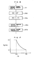
- the transient correction value ⁇ T may be corrected by the atmospheric pressure PA.
- the atmosphere correction of the transient correction value ⁇ T will now be described with reference to a flow chart shown in Fig. 16.
- the load correction coefficient KPM′ is read at step 1012d.
- the load correction coefficient KPM′ corresponds to a given atmospheric pressure (for example, 760 mmHg in the present embodiment) and is determined in accordance with the intake air pressure PM.
- the atmospheric pressure correction coefficient F2(P2) corresponding to the atmospheric pressure PA is read at subsequent step 1012e.
- the atmospheric pressure correction coefficient F2(PA) has a characteristic as shown in Fig. 17.
- a description of steps 1013 through 1015 (not shown) is omitted, since they are identical with those of the above-mentioned embodiment.
- the transient correction value which is set in accordance with transient conditions, is corrected to be decreased as atmospheric pressure decreases in accordance with the present invention as has been described in detail hereinabove, an appropriate fuel injection quantity may be obtained in compliance with the mutual relation between the deposition and evaporation of fuel in an intake manifold, so that a deviation of air fuel ratio under a transient condition may be prevented, even when the atmospheric pressure varies.
- An apparatus for controlling a quantity of fuel injected into an internal combustion engine (1) comprises a sensor (50) for detecting atmospheric pressure (PA), a sensor (51) for detecting a load condition of an internal combustion engine (1), and an electronic control device (20) including a microprocessor (CPU) (100).
- the CPU (100) functions to perform the processing steps including: step (52) of setting a reference fuel injection quantity (t) in accordance with a load condition of the engine (1), step (53) of detecting a transient condition of the engine (1), step (54) of setting a transient correction value ( ⁇ T) in accordance with the transient condition of the engine (1), step (55) of correcting the transient correction value ( ⁇ T) to be decreased as the atmospheric pressure (PA) decreases, and step (56) of setting a quantity of injection fule (TAU) supplied to the engine (1) in accordance with the set value of the reference fuel injection quantity (t) and the corrected transient correction value ( ⁇ T), whereby a deviation of an air fuel ratio from an appropriate value can be prevented even under a transient condition where atmospheric pressure (PA) varies.
- step (52) of setting a reference fuel injection quantity (t) in accordance with a load condition of the engine (1) step (53) of detecting a transient condition of the engine (1)
Landscapes
- Engineering & Computer Science (AREA)
- Chemical & Material Sciences (AREA)
- Combustion & Propulsion (AREA)
- Mechanical Engineering (AREA)
- General Engineering & Computer Science (AREA)
- Electrical Control Of Air Or Fuel Supplied To Internal-Combustion Engine (AREA)
Applications Claiming Priority (2)
| Application Number | Priority Date | Filing Date | Title |
|---|---|---|---|
| JP300036/89 | 1989-11-17 | ||
| JP1300036A JP2765126B2 (ja) | 1989-11-17 | 1989-11-17 | 燃料噴射量制御装置 |
Publications (3)
| Publication Number | Publication Date |
|---|---|
| EP0433671A2 true EP0433671A2 (de) | 1991-06-26 |
| EP0433671A3 EP0433671A3 (en) | 1991-12-18 |
| EP0433671B1 EP0433671B1 (de) | 1993-10-27 |
Family
ID=17879930
Family Applications (1)
| Application Number | Title | Priority Date | Filing Date |
|---|---|---|---|
| EP90121975A Expired - Lifetime EP0433671B1 (de) | 1989-11-17 | 1990-11-16 | Steuergerät der Kraftstoffeinspritzung mit Korrektion in Abhängigkeit des atmosphärischen Aussendrucks |
Country Status (6)
| Country | Link |
|---|---|
| US (1) | US5095877A (de) |
| EP (1) | EP0433671B1 (de) |
| JP (1) | JP2765126B2 (de) |
| KR (1) | KR0137132B1 (de) |
| CA (1) | CA2030040C (de) |
| DE (1) | DE69004232T2 (de) |
Cited By (4)
| Publication number | Priority date | Publication date | Assignee | Title |
|---|---|---|---|---|
| FR2721658A1 (fr) * | 1994-06-16 | 1995-12-29 | Bosch Gmbh Robert | Système de commande pour le dosage du carburant d'un moteur à combustion interne. |
| WO1998059161A1 (de) * | 1997-06-21 | 1998-12-30 | Mannesmann Vdo Ag | Verfahren und vorrichtung zur lastermittlung an einer brennkraftmaschine |
| US6035825A (en) * | 1993-10-21 | 2000-03-14 | Orbital Engine Company (Australia) Pty Limited | Control of fueling rate of an engine |
| EP0724686B1 (de) * | 1993-10-21 | 2001-04-04 | Orbital Engine Company (Australia) Pty. Ltd. | Steuerung der kraftstoffzufuhrrate eines motors |
Families Citing this family (7)
| Publication number | Priority date | Publication date | Assignee | Title |
|---|---|---|---|---|
| JPH06159114A (ja) * | 1992-11-24 | 1994-06-07 | Yamaha Motor Co Ltd | 内燃機関の空燃比制御装置 |
| US5622053A (en) * | 1994-09-30 | 1997-04-22 | Cooper Cameron Corporation | Turbocharged natural gas engine control system |
| JP3708161B2 (ja) * | 1995-04-24 | 2005-10-19 | 本田技研工業株式会社 | 電子式燃料噴射制御装置 |
| EP0810362B1 (de) * | 1995-10-02 | 2004-01-02 | Yamaha Hatsudoki Kabushiki Kaisha | Verfahren zur Steuerung einer Brennkraftmaschine |
| JP3453970B2 (ja) * | 1995-12-12 | 2003-10-06 | 株式会社デンソー | 内燃機関の燃料供給装置 |
| US6234149B1 (en) | 1999-02-25 | 2001-05-22 | Cummins Engine Company, Inc. | Engine control system for minimizing turbocharger lag including altitude and intake manifold air temperature compensation |
| JP5586733B1 (ja) * | 2013-04-17 | 2014-09-10 | 三菱電機株式会社 | 内燃機関の燃料噴射量制御装置および内燃機関の燃料噴射量制御方法 |
Family Cites Families (8)
| Publication number | Priority date | Publication date | Assignee | Title |
|---|---|---|---|---|
| JPS57148039A (en) * | 1981-03-10 | 1982-09-13 | Nissan Motor Co Ltd | Altitude corrector for engine fuel feeder |
| JPS57198343A (en) * | 1981-05-30 | 1982-12-04 | Mazda Motor Corp | Fuel feed device of engine |
| JPS57200631A (en) * | 1981-06-04 | 1982-12-08 | Toyota Motor Corp | Electronic controlling device for fuel injection type engine |
| JPS5885337A (ja) * | 1981-11-12 | 1983-05-21 | Honda Motor Co Ltd | 内燃エンジンの空燃比大気圧補正方法及び装置 |
| JPS59165850A (ja) * | 1983-03-09 | 1984-09-19 | Isuzu Motors Ltd | 電子制御気化器の制御方法 |
| JPH0745840B2 (ja) * | 1986-01-22 | 1995-05-17 | 本田技研工業株式会社 | 内燃エンジンの空燃比大気圧補正方法 |
| JPH0748328B2 (ja) * | 1987-06-29 | 1995-05-24 | 松下電器産業株式会社 | 電気接点 |
| JPH01125533A (ja) * | 1987-11-10 | 1989-05-18 | Fuji Heavy Ind Ltd | 内燃機関の燃料噴射制御装置 |
-
1989
- 1989-11-17 JP JP1300036A patent/JP2765126B2/ja not_active Expired - Fee Related
-
1990
- 1990-11-07 KR KR1019900017941A patent/KR0137132B1/ko not_active Expired - Fee Related
- 1990-11-15 CA CA002030040A patent/CA2030040C/en not_active Expired - Fee Related
- 1990-11-16 EP EP90121975A patent/EP0433671B1/de not_active Expired - Lifetime
- 1990-11-16 US US07/614,453 patent/US5095877A/en not_active Expired - Lifetime
- 1990-11-16 DE DE90121975T patent/DE69004232T2/de not_active Expired - Fee Related
Cited By (5)
| Publication number | Priority date | Publication date | Assignee | Title |
|---|---|---|---|---|
| US6035825A (en) * | 1993-10-21 | 2000-03-14 | Orbital Engine Company (Australia) Pty Limited | Control of fueling rate of an engine |
| EP0724686B1 (de) * | 1993-10-21 | 2001-04-04 | Orbital Engine Company (Australia) Pty. Ltd. | Steuerung der kraftstoffzufuhrrate eines motors |
| FR2721658A1 (fr) * | 1994-06-16 | 1995-12-29 | Bosch Gmbh Robert | Système de commande pour le dosage du carburant d'un moteur à combustion interne. |
| WO1998059161A1 (de) * | 1997-06-21 | 1998-12-30 | Mannesmann Vdo Ag | Verfahren und vorrichtung zur lastermittlung an einer brennkraftmaschine |
| US6456926B1 (en) | 1997-06-21 | 2002-09-24 | Mannesmann Vdo Ag | Method and device for determining load in an internal combustion engine |
Also Published As
| Publication number | Publication date |
|---|---|
| US5095877A (en) | 1992-03-17 |
| JPH03160131A (ja) | 1991-07-10 |
| CA2030040C (en) | 2000-05-30 |
| DE69004232D1 (de) | 1993-12-02 |
| JP2765126B2 (ja) | 1998-06-11 |
| KR910010050A (ko) | 1991-06-28 |
| EP0433671B1 (de) | 1993-10-27 |
| KR0137132B1 (ko) | 1998-04-25 |
| DE69004232T2 (de) | 1994-03-03 |
| CA2030040A1 (en) | 1991-05-18 |
| EP0433671A3 (en) | 1991-12-18 |
Similar Documents
| Publication | Publication Date | Title |
|---|---|---|
| US4886030A (en) | Method of and system for controlling fuel injection rate in an internal combustion engine | |
| US4454847A (en) | Method for controlling the air-fuel ratio in an internal combustion engine | |
| EP0478120B1 (de) | Verfahren und Vorrichtung zur Ableitung des den Innenverbrennungsmotor umgebenden atmosphärischen Druckes | |
| US5626122A (en) | Air-fuel ratio control apparatus for an internal combustion engine | |
| US5597951A (en) | Intake air amount-estimating apparatus for internal combustion engines | |
| US4938195A (en) | Atmospheric pressure detecting device for engine control | |
| US4471742A (en) | Fuel supply control method for an internal combustion engine equipped with a supercharger | |
| JP2602031B2 (ja) | 内燃機関の電子制御装置 | |
| US5615657A (en) | Method and apparatus for estimating intake air pressure and method and apparatus for controlling fuel supply for an internal combustion engine | |
| GB2213290A (en) | Fuel injection control system for i/c engine | |
| US5095877A (en) | Fuel injection control apparatus having atmospheric pressure correction function | |
| US5950598A (en) | Method for determining the injection time for a direct-injection internal combustion engine | |
| US5520153A (en) | Internal combustion engine control | |
| GB2190202A (en) | System for measuring the quantity of intake air in an engine | |
| US4807581A (en) | System for controlling the operation of an internal combustion engine | |
| US5251599A (en) | Internal combustion engine control device having exhaust gas recycle system | |
| US5027779A (en) | Fuel injection control apparatus for an internal combustion engine | |
| EP0199457B1 (de) | Steuerverfahren für die Kraftstoffzufuhr für Brennkraftmaschinen bei Tieftemperatur | |
| US4508084A (en) | Method for controlling a fuel metering system of an internal combustion engine | |
| EP0156356B1 (de) | Verfahren zur Steuerung der Kraftstoffzufuhr eines Innenverbrennungsmotors | |
| GB2141840A (en) | Fuel injection control method for multi-cylinder internal combustion engines of sequential injection type at acceleration | |
| US4538578A (en) | Air-fuel ratio control for an internal combustion engine | |
| JP2871992B2 (ja) | エンジン制御用大気圧検出装置 | |
| EP1930576A2 (de) | Vorrichtung und Verfahren zur Steuerung eines Verbrennungsmotors | |
| JPH0223698B2 (de) |
Legal Events
| Date | Code | Title | Description |
|---|---|---|---|
| PUAI | Public reference made under article 153(3) epc to a published international application that has entered the european phase |
Free format text: ORIGINAL CODE: 0009012 |
|
| AK | Designated contracting states |
Kind code of ref document: A2 Designated state(s): DE FR GB |
|
| PUAL | Search report despatched |
Free format text: ORIGINAL CODE: 0009013 |
|
| AK | Designated contracting states |
Kind code of ref document: A3 Designated state(s): DE FR GB |
|
| 17P | Request for examination filed |
Effective date: 19920206 |
|
| 17Q | First examination report despatched |
Effective date: 19920416 |
|
| GRAA | (expected) grant |
Free format text: ORIGINAL CODE: 0009210 |
|
| AK | Designated contracting states |
Kind code of ref document: B1 Designated state(s): DE FR GB |
|
| REF | Corresponds to: |
Ref document number: 69004232 Country of ref document: DE Date of ref document: 19931202 |
|
| ET | Fr: translation filed | ||
| PLBE | No opposition filed within time limit |
Free format text: ORIGINAL CODE: 0009261 |
|
| STAA | Information on the status of an ep patent application or granted ep patent |
Free format text: STATUS: NO OPPOSITION FILED WITHIN TIME LIMIT |
|
| 26N | No opposition filed | ||
| REG | Reference to a national code |
Ref country code: FR Ref legal event code: D6 |
|
| REG | Reference to a national code |
Ref country code: GB Ref legal event code: IF02 |
|
| PGFP | Annual fee paid to national office [announced via postgrant information from national office to epo] |
Ref country code: FR Payment date: 20031110 Year of fee payment: 14 |
|
| PGFP | Annual fee paid to national office [announced via postgrant information from national office to epo] |
Ref country code: GB Payment date: 20031112 Year of fee payment: 14 |
|
| PGFP | Annual fee paid to national office [announced via postgrant information from national office to epo] |
Ref country code: DE Payment date: 20031127 Year of fee payment: 14 |
|
| PG25 | Lapsed in a contracting state [announced via postgrant information from national office to epo] |
Ref country code: GB Free format text: LAPSE BECAUSE OF NON-PAYMENT OF DUE FEES Effective date: 20041116 |
|
| PG25 | Lapsed in a contracting state [announced via postgrant information from national office to epo] |
Ref country code: DE Free format text: LAPSE BECAUSE OF NON-PAYMENT OF DUE FEES Effective date: 20050601 |
|
| GBPC | Gb: european patent ceased through non-payment of renewal fee |
Effective date: 20041116 |
|
| PG25 | Lapsed in a contracting state [announced via postgrant information from national office to epo] |
Ref country code: FR Free format text: LAPSE BECAUSE OF NON-PAYMENT OF DUE FEES Effective date: 20050729 |
|
| REG | Reference to a national code |
Ref country code: FR Ref legal event code: ST |