EP0433698A2 - Eichung eines schwarzen Strahlers mit Hilfe von Bildverarbeitungstechniken - Google Patents
Eichung eines schwarzen Strahlers mit Hilfe von Bildverarbeitungstechniken Download PDFInfo
- Publication number
- EP0433698A2 EP0433698A2 EP90122414A EP90122414A EP0433698A2 EP 0433698 A2 EP0433698 A2 EP 0433698A2 EP 90122414 A EP90122414 A EP 90122414A EP 90122414 A EP90122414 A EP 90122414A EP 0433698 A2 EP0433698 A2 EP 0433698A2
- Authority
- EP
- European Patent Office
- Prior art keywords
- temperature
- function
- differential temperature
- differential
- calibrated
- Prior art date
- Legal status (The legal status is an assumption and is not a legal conclusion. Google has not performed a legal analysis and makes no representation as to the accuracy of the status listed.)
- Ceased
Links
- 238000000034 method Methods 0.000 title claims abstract description 29
- 238000012545 processing Methods 0.000 title claims description 6
- 238000003331 infrared imaging Methods 0.000 claims abstract description 6
- 238000003384 imaging method Methods 0.000 claims description 11
- 238000012935 Averaging Methods 0.000 claims 1
- 230000006870 function Effects 0.000 description 32
- 230000008569 process Effects 0.000 description 11
- 238000012360 testing method Methods 0.000 description 10
- 238000001931 thermography Methods 0.000 description 9
- 230000008901 benefit Effects 0.000 description 4
- 238000012937 correction Methods 0.000 description 3
- 238000010586 diagram Methods 0.000 description 3
- 230000003287 optical effect Effects 0.000 description 2
- 230000001934 delay Effects 0.000 description 1
- 238000001514 detection method Methods 0.000 description 1
- 238000012986 modification Methods 0.000 description 1
- 230000004048 modification Effects 0.000 description 1
- 238000012544 monitoring process Methods 0.000 description 1
- 230000008520 organization Effects 0.000 description 1
- 230000005855 radiation Effects 0.000 description 1
- 238000010561 standard procedure Methods 0.000 description 1
- 238000010998 test method Methods 0.000 description 1
Images


Classifications
-
- G—PHYSICS
- G01—MEASURING; TESTING
- G01J—MEASUREMENT OF INTENSITY, VELOCITY, SPECTRAL CONTENT, POLARISATION, PHASE OR PULSE CHARACTERISTICS OF INFRARED, VISIBLE OR ULTRAVIOLET LIGHT; COLORIMETRY; RADIATION PYROMETRY
- G01J5/00—Radiation pyrometry, e.g. infrared or optical thermometry
- G01J5/52—Radiation pyrometry, e.g. infrared or optical thermometry using comparison with reference sources, e.g. disappearing-filament pyrometer
- G01J5/53—Reference sources, e.g. standard lamps; Black bodies
Definitions
- the present invention generally relates to apparatus for testing infrared (IR) sensors, and is directed more particularly to apparatus for calibrating black body differential temperature sources that are utilized in testing IR sensors.
- IR infrared
- Infrared sensors are utilized to produce data based on the thermal signature of the scene being viewed, and are commonly tested relative to differential temperature sources (also referred to as black body sources) such as those commercially available from Electro Optical Industries, Inc., Santa Barbara, California.
- differential temperature sources also referred to as black body sources
- Differential temperature sources typically include a target plate having an apertured pattern and a controlled plate, with the target plate being closer to the IR imaging system being tested.
- the temperature difference between the target plate and the controlled plate is controlled pursuant to an input differential temperature setting (i.e., the desired temperature difference between the plates) by a temperature controller, for example by monitoring both plates and leaving the target plate at ambient temperature while controlling the temperature of the controlled plate.
- the temperature controller of a differential temperature source provides an indicated differential temperature information in the form of a human viewable display as well as a data output, for example on a bus conforming to the IEEE 488 standard.
- the relation between the indicated differential temperature and the actual differential temperature may not always be known, and for testing purposes the differential temperature source must be calibrated so that actual differential temperatures can be calculated from indicated differential temperatures.
- a known technique for differential temperature source calibration involves utilizing a digital temperature thermometer (DTT) to obtain the actual differential temperatures over a range of indicated differential temperatures.
- DTT digital temperature thermometer
- the differences between indicated differential temperature values and the corresponding actual differential temperatures are utilized as correction factors that can be applied to the readout values. Additionally, collimator efficiency and target emissivity correction factors are calculated separately.
- Another advantage would be to provide apparatus for calibrating differential temperature sources which calculates calibration information that takes into account collimator efficiency and target emissivity without separate calculations.
- a process for calibrating differential temperature sources which includes the step of providing a calibrated infrared imaging sensor having an associated calibrated temperature function that is expressed as a function of a predetermined calculated parameter which is indicative of the actual differential temperature of a differential temperature source.
- the temperature source being calibrated is thermally imaged at indicated differential temperatures to provide thermal images associated with the indicated temperatures.
- the predetermined calculated parameter indicative of the actual differential temperature of the imaged temperature source is calculated for the different indicated temperatures, and a calculated parameter function is determined as a function of indicated temperature.
- the calculated parameter function is then substituted in the calibrated temperature function to provide a calibrated temperature function that is expressed as a function of indicated differential temperature.
- the invention also contemplates calibration apparatus that includes a calibrated infrared imaging sensor having an associated calibrated temperature function that is expressed as a function of a predetermined calculated parameter indicative of the actual differential temperature of a differential temperature source.
- the sensor provides video outputs for different indicated differential temperatures provided by the differential temperature source under calibration to a processor which determines a calculated parameter function that defines the predetermined calculated parameter as a function of indicted differential temperature.
- the processor further substitutes the calculated parameter function in the calibrated temperature function to provide a calibrated temperature function that is a function of indicated differential temperature.
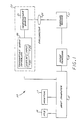
- FIG. 1 is a block diagram of an illustrative example of a differential temperature source calibration system in accordance with the invention.
- FIG. 2 is a flow diagram of an illustrative example of a process that can be utilized to calibrate the IR imaging sensor of the calibration system of FIG. 1.
- FIG. 3 is a flow diagram of an illustrative example of process that can be utilized by the calibration system of FIG. 1 to calibrate a differential temperature source.
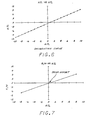
- FIG. 4 is a graph schematically depicting calibration data for the IR imaging sensor of the calibration system of FIG. 1.
- FIG. 5 is a graph schematically depicting calibration data for a differential temperature source being calibrated with the calibration system of FIG. 1.
- FIG. 6 is a graph schematically depicting calculated calibration data for a differential temperature source that has been calibrated with the calibration system of FIG. 1.
- FIG. 7 is a graph schematically depicting a process for determining the temperature offset for a differential temperature source known to have a constant offset.
- the calibration system 10 includes a thermal imaging sensor 11 that provides video outputs to an image processor 13.
- the imaging sensor 11 provides standard analog video to the image processor 13 which converts the video outputs into digital video which it stores.
- the image processor 13 is controlled, for example, by a host computer 15 that is coupled to a video monitor 17 which can be utilized to display the output of the image processor 13 and display communications from the host computer 15.
- a keyboard 19 provides inputs to the host computer 15.
- the differential temperature source 20 includes a differential temperature target 21 and a controller 30 for controlling the differential temperature exhibited by the differential temperature target 21.
- the controller 20 includes a temperature input 23, switches for example, by which the desired differential temperatures is input to the controller 30.
- the controller 30 further includes a display 25 for displaying indicated differential temperature (i.e., what the controller detects as the differential temperature). Temperature inputs and indicated differential temperature data can also be communicated between the host computer 15 and the differential temperature source via an appropriate bus or communications channel.
- a collimator 27 provides collimated infrared radiation to the thermal imaging sensor 11, as is common on infrared sensor test stations.
- digital video data comprises intensity or gray level values (e.g., having a range of 0 to 255) associated with respective pixels in respective frames, where for example each frame corresponds to one complete scan by the imaging sensor 11. Since the video data is in digital form, it can be processed and utilized pursuant to digital techniques, as employed by the invention.
- intensity or gray level values e.g., having a range of 0 to 255
- the technique of the invention essentially determines the relation between indicated differential temperature ⁇ T i and actual or calibrated differential temperature ⁇ T c .
- DTT digital temperature thermometer
- f(A) f(A)
- A g( ⁇ T i )
- the calculated parameter function g( ⁇ T i ) is then substituted in the differential temperature function f(A) to provide a differential temperature function that is a function of indicated differential temperature ⁇ T i :
- ⁇ T c f(g( ⁇ T i ))
- the sum ⁇ is readily calculated pursuant to known maxima and minima detection techniques from an averaged data frame which is the average of a plurality of image frames, for example 256 frames.
- the standard deviation N of the random noise is also calculated by known techniques, for example by subtracting the averaged data frame from an image frame that was not utilized in defining the averaged frame.
- the resulting difference frame represents random noise, and the standard deviation of the random noise frame is calculated pursuant to standard techniques.
- FIG. 2 shown therein is an illustrative example of a process for defining the calibrated differential temperature function f(A).
- an iteration count value K is initialized to 1.
- An actual differential temperature ⁇ T c (K) is set at 113, such actual differential temperature being selected so as to provide for an appropriate range of positive and negative actual differential temperatures ⁇ T c (1) through ⁇ T c (L), where L is the number of samples to be taken.
- the count value K is incremented by 1 at 117, and a determination is made at 119 as to whether the count value K is greater than the predetermined limit L. If yes, indicating that L values of the calculated parameter A have been measured, processing continues at 121. If no, processing continues with 113.
- the calibrated temperature function f(A) is determined from the stored data, for example by known numerical techniques, and is stored.
- FIG. 4 is a graph that schematically illustrates the ⁇ T c vs. ⁇ /N calibration data for an thermal imaging sensor that is generally linear (i.e., the actual differential temperature ⁇ T c and the calculated parameter ⁇ /N have a linear relation).
- FIG. 3 shown therein is an illustrative example of a process for deriving the calculated parameter function g( ⁇ T i ).
- an iteration count value K is initialized to 1.
- An indicated (i.e., displayed) differential temperature ⁇ T i (K) is set at 213, such indicated differential temperature being selected so as to provide for an appropriate range of positive and negative indicated differential temperatures ⁇ T i (1) through ⁇ T i (M), where M is the number of samples to be taken.
- the calculated parameter A is calculated and stored in memory together with the associated indicated differential temperature ⁇ T i (K).
- the count value K is incremented by 1 at 217, and a determination is made at 219 as to whether the count value K is greater than a predetermined limit M. If yes, indicating that M values of the calculated parameter A have been measured, processing continues at 221. If no, processing continues at 213.
- a 221 the measured parameter function g( ⁇ T i ) is determined from the stored data, for example by known numerical techniques.
- the calculated parameter function g( ⁇ T i ) is substituted in the calibrated differential temperature function f(A) for the calibrated thermal imaging sensor 11 to provide for the differential temperature source a calibrated temperature function that is a function of indicated differential temperature.
- FIG. 5 is a graph that schematically illustrates the ⁇ /N vs. ⁇ T i calibration data for a differential temperature source that is being calibrated with a thermal imaging sensor that was calibrated pursuant to the process of FIG. 2 and which exhibited calibration data as depicted in FIG. 4.
- FIG. 6 is a graph that schematically illustrates ⁇ T c vs. ⁇ T i calibration data for a differential temperature source calibrated pursuant to the processes of FIGS. 2 and 3 and which utilized calibration data as in FIGS. 4 and 5.
- the thermal sensor calibration process of FIG. 2 can alternatively be performed with a calibrated differential temperature source at a thermal sensor test station and without a DTT.
- the calibrated differential temperature of the differential temperature source (as determined by the host computer from indicated temperature, for example) would be utilized at 113 as ⁇ T a .
- an abbreviated calibration can be utilized, assuming a substantially linear thermal imaging sensor calibration.
- the calculated parameter ⁇ /N can be measured for a positive indicated differential temperature and a negative indicated differential temperature.
- the line defined by the two data points is calculated pursuant to standard algebraic techniques, and a constant offset is defined by the indicated temperature when the calculated parameter ⁇ /N is set to 0. This process is schematically depicted in the graph of FIG. 7 wherein the offset is defined by the intersection of the line with the indicated differential temperature axis.
- the foregoing has been a disclosure of a differential temperature source calibration technique and system which advantageously provides for calibration at an IR imaging sensor test station and without the use of a digital temperature thermometer.
- the calibration technique and system further provides for temperature source calibration without disrupting IR imaging sensor test procedures and test alignments. Also, the calibration technique and system implicitly accounts for collimator efficiency and target emissivity without the need for separate calculations.
Landscapes
- Physics & Mathematics (AREA)
- General Physics & Mathematics (AREA)
- Spectroscopy & Molecular Physics (AREA)
- Radiation Pyrometers (AREA)
- Photometry And Measurement Of Optical Pulse Characteristics (AREA)
- Transforming Light Signals Into Electric Signals (AREA)
Applications Claiming Priority (2)
| Application Number | Priority Date | Filing Date | Title |
|---|---|---|---|
| US45213589A | 1989-12-18 | 1989-12-18 | |
| US452135 | 1989-12-18 |
Publications (2)
| Publication Number | Publication Date |
|---|---|
| EP0433698A2 true EP0433698A2 (de) | 1991-06-26 |
| EP0433698A3 EP0433698A3 (en) | 1992-05-27 |
Family
ID=23795187
Family Applications (1)
| Application Number | Title | Priority Date | Filing Date |
|---|---|---|---|
| EP19900122414 Ceased EP0433698A3 (en) | 1989-12-18 | 1990-11-23 | Black body calibration using image processing techniques |
Country Status (4)
| Country | Link |
|---|---|
| EP (1) | EP0433698A3 (de) |
| JP (1) | JPH049626A (de) |
| IL (1) | IL96336A (de) |
| TR (1) | TR25167A (de) |
Cited By (3)
| Publication number | Priority date | Publication date | Assignee | Title |
|---|---|---|---|---|
| EP0797362A1 (de) * | 1996-03-21 | 1997-09-24 | Nederlandse Organisatie Voor Toegepast-Natuurwetenschappelijk Onderzoek Tno | Vorrichtung zur Prüfung von optischen und elektrooptischen Bildbetrachtungssystemen |
| CN112262301A (zh) * | 2019-02-12 | 2021-01-22 | 株式会社优利电子 | 利用热成像相机的温度测量装置、方法及计算机可读记录介质 |
| CN112556858A (zh) * | 2020-12-07 | 2021-03-26 | 深圳市优必选科技股份有限公司 | 黑体检测方法、测温机器人、终端设备及存储介质 |
-
1990
- 1990-11-13 IL IL9633690A patent/IL96336A/en not_active IP Right Cessation
- 1990-11-23 EP EP19900122414 patent/EP0433698A3/en not_active Ceased
- 1990-12-18 TR TR90/1204A patent/TR25167A/xx unknown
- 1990-12-18 JP JP2411524A patent/JPH049626A/ja active Pending
Non-Patent Citations (4)
| Title |
|---|
| I.J. SPIRO (ED.) 'PROCEEDINGS OF SPIE, VOL. 972, INFRARED TECHNOLOGY XIV' 1988 , SPIE , BELLINGHAM , US , PAGES 246 - 255 A. DANIELS ET AL. : " A radiometric method of calibrating infrared sources, using the SR 5000 infrared spectroradiometer " * |
| 'PROCEEDINGS OF SPIE, VOL 98, ASSESSMENT OF IMAGING SYSTEMS' 1976 , SPIE , BELLINGHAM , US , PAGES 96 - 104 A.R. NEWBERY ET AL.: "The laboratory evaluation of thermal imaging systems " * |
| T.L. WILLIAMS (ED.) 'PROCEEDINGS OF SPIE, VOL. 274, ASSESSMENT OF IMAGING SYSTEMS: VISIBLE AND INFRARED' 1981 , SPIE , BELLINGHAM , US , PAGES 268 - 272 A.R. NEWBERY ET AL.: " Use of minimum resolvable temperature difference (MRTD) for the evaluation and specification of thermal imaging systems " * |
| T.L. WILLIAMS (ED.) 'PROCEEDINGS OF SPIE, VOL. 274, ASSESSMENT OF IMAGING SYSTEMS: VISIBLE AND INFRARED' 1981 , SPIE , BELLINGHAM , US , PAGES 273 - 279 T.L. WILLIAMS ET AL. : " Testing thermal imaging systems " * |
Cited By (4)
| Publication number | Priority date | Publication date | Assignee | Title |
|---|---|---|---|---|
| EP0797362A1 (de) * | 1996-03-21 | 1997-09-24 | Nederlandse Organisatie Voor Toegepast-Natuurwetenschappelijk Onderzoek Tno | Vorrichtung zur Prüfung von optischen und elektrooptischen Bildbetrachtungssystemen |
| CN112262301A (zh) * | 2019-02-12 | 2021-01-22 | 株式会社优利电子 | 利用热成像相机的温度测量装置、方法及计算机可读记录介质 |
| CN112262301B (zh) * | 2019-02-12 | 2024-09-10 | 株式会社优利电子 | 利用热成像相机的温度测量装置、方法及计算机可读记录介质 |
| CN112556858A (zh) * | 2020-12-07 | 2021-03-26 | 深圳市优必选科技股份有限公司 | 黑体检测方法、测温机器人、终端设备及存储介质 |
Also Published As
| Publication number | Publication date |
|---|---|
| EP0433698A3 (en) | 1992-05-27 |
| IL96336A0 (en) | 1991-08-16 |
| IL96336A (en) | 1994-08-26 |
| JPH049626A (ja) | 1992-01-14 |
| TR25167A (tr) | 1992-11-01 |
Similar Documents
| Publication | Publication Date | Title |
|---|---|---|
| US5128884A (en) | Black body calibration using image processing techniques | |
| CN111595462B (zh) | 红外成像测温系统标定方法、装置、计算设备及存储介质 | |
| CN112798110A (zh) | 一种基于标定拟合的红外热成像设备温度检测方法 | |
| KR100668025B1 (ko) | 온도 보정 처리 장치 | |
| EP1678485B1 (de) | Verfahren und ir-kamera zur bestimmung der kondensationsgefahr | |
| CN112556856B (zh) | 一种红外测温修正方法、装置及电子设备 | |
| KR102211136B1 (ko) | 흑체를 구비한 온도 계측 시스템 및 방법 | |
| CN114518175A (zh) | 一种红外热成像图像的温度矫正方法以及相关装置 | |
| JP2019213193A (ja) | 赤外線撮像装置及びそれに用いられるプログラム | |
| EP0433698A2 (de) | Eichung eines schwarzen Strahlers mit Hilfe von Bildverarbeitungstechniken | |
| Chrzanowski et al. | Testing and evaluation of thermal cameras for absolute temperature measurement | |
| CN111207833B (zh) | 一种基于图像数据归一化技术的测温方法 | |
| CN119359827A (zh) | 一种基于工业相机的亮度标定方法、系统及装置 | |
| CN115900973B (zh) | 红外热电堆传感器温度补偿、校正方法、补偿装置及电子设备 | |
| KR20210155223A (ko) | 열화상 카메라 | |
| Beasley et al. | Calibration and nonuniformity correction of MICOM's diode-laser-based infrared scene projector | |
| Hejazi et al. | Scope and limitations of thermal imaging using multiwavelength infrared detection | |
| JPH06186085A (ja) | 温度計測方法及びその装置 | |
| KR101092207B1 (ko) | 비선형 응답특성을 가지는 디지털 방사선 검출 이미지의 밸런스 보정 방법 및 장치 | |
| JPH1096667A (ja) | 赤外線熱画像装置およびその光学系毎の温度変換テーブル作成回路 | |
| JP3243113B2 (ja) | 赤外線センサにおけるオフセット値生成装置、オフセット及びゲインの補正方法並びに温度測定誤差補正装置 | |
| Hughett et al. | Image processing software for real time quantitative infrared thermography | |
| EP4379312B1 (de) | System und verfahren zur handhabung einer thermischen kompensation | |
| JP3358683B2 (ja) | 温湿度測定方法及び装置 | |
| Cooper et al. | Calibration and Non-Uniformity Correction of MICOM's Diode Laser Based Infrared Scene Projector |
Legal Events
| Date | Code | Title | Description |
|---|---|---|---|
| PUAI | Public reference made under article 153(3) epc to a published international application that has entered the european phase |
Free format text: ORIGINAL CODE: 0009012 |
|
| AK | Designated contracting states |
Kind code of ref document: A2 Designated state(s): BE CH DE ES FR GB IT LI NL SE |
|
| PUAL | Search report despatched |
Free format text: ORIGINAL CODE: 0009013 |
|
| AK | Designated contracting states |
Kind code of ref document: A3 Designated state(s): BE CH DE ES FR GB IT LI NL SE |
|
| 17P | Request for examination filed |
Effective date: 19920917 |
|
| 17Q | First examination report despatched |
Effective date: 19931210 |
|
| STAA | Information on the status of an ep patent application or granted ep patent |
Free format text: STATUS: THE APPLICATION HAS BEEN REFUSED |
|
| 18R | Application refused |
Effective date: 19950821 |