EP0433798A2 - Dispositif de changement d'une plaque d'impression - Google Patents
Dispositif de changement d'une plaque d'impression Download PDFInfo
- Publication number
- EP0433798A2 EP0433798A2 EP90123550A EP90123550A EP0433798A2 EP 0433798 A2 EP0433798 A2 EP 0433798A2 EP 90123550 A EP90123550 A EP 90123550A EP 90123550 A EP90123550 A EP 90123550A EP 0433798 A2 EP0433798 A2 EP 0433798A2
- Authority
- EP
- European Patent Office
- Prior art keywords
- plate
- clamping
- printing plate
- printing
- plate cylinder
- Prior art date
- Legal status (The legal status is an assumption and is not a legal conclusion. Google has not performed a legal analysis and makes no representation as to the accuracy of the status listed.)
- Granted
Links
Images


Classifications
-
- B—PERFORMING OPERATIONS; TRANSPORTING
- B41—PRINTING; LINING MACHINES; TYPEWRITERS; STAMPS
- B41F—PRINTING MACHINES OR PRESSES
- B41F27/00—Devices for attaching printing elements or formes to supports
- B41F27/12—Devices for attaching printing elements or formes to supports for attaching flexible printing formes
- B41F27/1206—Feeding to or removing from the forme cylinder
Definitions
- the invention relates to a method and a device for carrying out the method for automatically feeding a printing plate to and discharging a plate cylinder of a rotary printing press.
- a disadvantage of the device according to EP application. 02 68 857 is that the pressure plate must be inserted into the clamping device by hand; In addition, the commands for placing the pressure plate, clamping and clamping must be entered manually on a control panel.
- the invention has for its object to provide a method for feeding and discharging a printing plate to and from a plate cylinder and a device for performing the method.
- the advantage of the method and the device according to the invention is, in particular, that for attaching the printing plates to the plate cylinder Auxiliary staff can be used. Touching the personnel with the rotating parts of the machine is excluded, ie safety is increased. Machine downtimes for changing the printing plates are reduced.
- a position relevant to the plate on the plate cylinder becomes more precise. A waste of paper waste caused by lengthy registration correction is reduced.
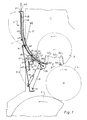
- a rotary printing press has several printing units 1 (e.g. 4), each of which, among other things. a plate cylinder 3, a blanket cylinder 4 and an impression cylinder 6 included. These are stored in the usual way in side frames of the rotary printing press.
- a printing plate feed or removal device 9 is provided on an access side 8 to the cylinders 3, 4, 6 of the printing unit 1. This is attached to a cover plate 11, which together with the pressure plate feed or discharge device 9 by means of two rockers (arms) 17; 18, which are fastened to the side frames of the printing towers 1, are arranged pivotably in two end positions.
- the swivel radius is shown by dashed lines.
- an upper and lower joint 14; 16 provided, in each of which a first end of the rockers 17; 18 is pivotally mounted.
- a second end of the rockers 17, 18 is pivotally mounted on the side frames.
- the cover plate 11 as a coupling, the wings 17, 18 and the frame of the printing unit 1 as a web thus form a four-bar link.
- a working cylinder 19 is pivotally mounted on a lower end on both sides of the cover plate 11.
- a piston rod 21 of the working cylinder 19 is articulated to a lever 22.
- the lever 22 rotatably supports a continuous pressure roller 26 arranged parallel to the axis of the plate cylinder 3.
- the pressure roller 26 can also be offset.
- the pressure roller 26 has a soft surface (e.g. rubber; plastic) in relation to a pressure plate 27.
- the lever 22 is pivotally mounted about an axis 30 of a drive roller 29 rotatably mounted in side supports (not shown) of the cover plate 11.
- the drive roller 29 is offset and has a drive (z. B. gear drive, electric motor, etc.).
- this is represented schematically by a chain wheel 31 with a drive chain 32.
- the drive roller 29 and the pressure roller 26 are also in drive connection, wherein they preferably have the same peripheral speeds.
- a pressure roller 33 can be brought into contact with a drive roller 29.
- the pressure roller 33 is rotatably mounted in a first end of a two-armed lever 34.
- the lever 34 is pivotably mounted almost centrally in the side supports of the cover plate 11 and has a joint 36 at a second end, which is connected to one end of a piston rod 37.
- the piston rod 37 is part of a working cylinder 40 which is articulated to the cover plate 11.
- the printing plate feed or discharge device 9 consists of an approximately printing plate-wide housing 38 with a storage chamber 39.
- the housing 38 has a slight curvature such that an upper part of the housing 38 is aligned almost vertically and a lower part of the Housing 38 is oriented tangentially to a lower part of the plate cylinder 3.
- a funnel-shaped opening 41 in the upper part of the housing 38 facilitates the insertion of the pressure plate 27.
- the housing 38 is made in two parts and has a hinge 42 above the cover plate 11, by means of which an upper part of the housing 38 can be folded down, whereby an upper part of the printing tower 1, in which an inking unit (not shown) in the usual manner Printing machine is provided, is accessible to an operator.
- a front wall 43 of the housing 38 extends up to shortly before the pressure roller 26 and has openings 44 in the area of the drive roller 29, through which surface areas of the remote drive roller 29 protrude into the storage chamber 39.
- a rear wall 46 of the housing 38 extends shortly before the pressure roller 33.
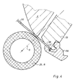
- a plurality of ejection fingers 45 are provided parallel to the front wall 43, which are fixedly arranged on an ejection finger shaft 47 pivotably mounted in the side supports of the cover plate 11.
- a drive device for the ejection finger shaft 47 is shown in FIG. 2. At a distance from the pivotable mounting of the ejection finger shaft 47, a piston rod 48 articulates on a lever 50 of the ejection finger shaft 47.
- the piston rod 48 is part of a working cylinder 49, the is articulated to the cover plate 11.
- the ejection fingers 45 are pivoted by means of the piston rod 48 in such a way that their tips 68 can dip into the periphery 62 of the plate cylinder 3 or lift off over the periphery.
- Means are also provided (not shown) which cause the ejection fingers 45 to be able to dip into the periphery 62 of the plate cylinder only in the area of the plate cylinder pit 2.
- the plate cylinder 3 has a plate clamping and tensioning device 53, 54 in a pit 52.
- the plate clamp is e.g. known from DE-PS 36 26 936. This is particularly characterized by a conveniently arranged pivot pole of the clamping flap 55; 56 out. This has the effect that a pressure plate end 57 is not hindered by the clamping flap 55 when it is inserted into or removed from the plate clamping device 54.
- the jig is e.g. known from DE-OS 36 04 071.
- actuating means for the plate clamping and tensioning device 53, 54 are supplied with working medium via a rotary entry on the plate cylinder journal.
- the actuating means can act hydraulically, pneumatically, mechanically or also electrically.
- the printing plate feed or discharge device 9 is in a position according to FIGS. 1 and 2. In this position, access to the cylinders 3, 4, 6 is closed by the cover plate 11, but the pressure roller 26 is pivoted from the plate cylinder 3 (not shown).
- the cover plate 11 has a view (not shown) on the plate cylinder 3.
- the plate cylinder 3 moves into the predetermined angular position A (FIG. 2).
- the clamping flap 55 is opened.
- a pressure plate end 57 pivots outward due to its elastic inherent tension until it rests against a lower part of the front wall 43 or is lifted from the clamping support 63 by the ejection fingers 45 by rotating the plate cylinder 3 into the pressure plate clamping position C by the ejection fingers 45.
- the pressure plate end 57 thereby comes into a nip of the transport rollers (drive roller / Pressure roller) 29, 33, which grip the printing plate end 57 and transport the printing plate 27 further at the same or greater peripheral speed as the plate cylinder 3, when the clamping flap 56 of the plate clamping and tensioning device 53 for the printing plate start 58 in the plate cylinder angle position B (printing plate feed position) (FIG 1) or was opened shortly before.
- the pressure plate 27 is transported by the transport rollers 29, 33 until the pressure plate end 57 of the pressure plate 27 has left the nip, i.e. is transported out of the lower part of the printing plate feed or discharge device 9. An operator can now grasp the pressure plate end 57 and remove the pressure plate 27 from the storage chamber 39.
- the plate cylinder 3 is now rotated counterclockwise (forward) while the pressure roller 26 presses the pressure plate 60 against the plate cylinder 3. If the position detector 59 signals that the printing plate 60 is not in good contact with the stop 51 of the plate clamping device 54, the printing plate clamping process is terminated and an interference signal is generated.
- the position C is subdivided into angular degrees only slightly (approx. 5 ° - 10 °) behind the disposal position A, i.e. H. the plate cylinder 3 only has to be rotated a little bit counterclockwise from the disposal position A until it reaches position C (FIG. 3).
- the pressure roller 26 has slightly bent the pressure plate end 57 around an edge 61 of the plate cylinder pit 52, so that the pressure plate end 57 comes to lie within the periphery 62 of the plate cylinder 3 on the clamping support 63 of the clamping device 54 before it comes off the clamping flap 55 is held.
- the pressure roller 26 is then pivoted back into the printing press operating position in that the double-acting working cylinder 19 pressurizes the piston rod 21, and the pressure roller 26 swivels about the axis 30 of the drive roller 29 from the plate cylinder 3.
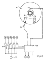
- the control computer 66 is connected to a number of solenoid valves 67 which, in the event of a command, switch or supply printing plate in the correct sequence depending on the positions of the plate cylinder 3 and in conjunction with suitable software and supply the actuating cylinders with working medium from a pressure source 72.
- the positions A, B, C of the plate cylinder 3 are determined by means of an angle encoder 71 and fed to the control computer 66 (FIG. 4).
- All electrical drives e.g. plate cylinder drive M, drive for the transport roller 33
- All electrical drives are also controlled by means of the control computer 66.
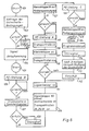
- FIG. 6 shows the diagram of a flow chart according to which the control computer 66 works in conjunction with counters and other position indicators (e.g. rotary pulse encoder 71) so that the printing plate 60 is automatically fed to the plate cylinder 3.
- the control computer 66 works in conjunction with counters and other position indicators (e.g. rotary pulse encoder 71) so that the printing plate 60 is automatically fed to the plate cylinder 3.
- a query 102 of the safety conditions (for example, is the cover plate 11 closed?) Is carried out. Appropriate sensors are then activated. Not all If safety conditions are met, an interference signal 103 is generated.
- a start warning signal 104 is given when all safety conditions are met.
- a renewed actuation of the start trigger 101 activates a drive of the plate cylinder 3 and rotates it into the plate cylinder position B (printing plate feed position) 106.
- the drive stops.
- a subsequent query 107 relates to the presence of a new printing plate 60 in the printing plate feed or discharge device 9. Sensors provided but not shown to signal that the new printing plate 60 is missing, an interference signal 108 is generated.
- a step 109 the clamping flap 56 is opened, the pressure roller 26 is placed against the plate cylinder 3, and the drive for all transport rollers 26, 29, 33 is activated.
- the position detector 59 is then queried in a step 111. If the position of the pressure plate 60 on the stops 51 is incorrect, a further feed 112 of the pressure plate takes place. After three negative decisions 113, the transport rollers 26, 29, 33 are driven in reverse so that the printing plate 60 is transported back into the storage chamber 39; an interference signal 114 is also generated.
- step 116 If the pressure plate 60 is correctly positioned, the drive for the transport rollers 26, 29, 33 is switched off in a step 116.
- the clamping flap 56 is then closed in step 117 and the pressure roller 33 of in step 118 the drive roller 29 turned off.
- An activation 119 of the plate cylinder drive rotates the plate cylinder 3 forward into the plate cylinder position A.
- the clamping flap 55 is opened in a step 121 and the plate clamping device 54 is moved to zero.
- step 122 the plate cylinder 3 is moved into the plate cylinder position C.
- the plate cylinder 3 is not stopped between positions A and C.
- FIG. 7 shows the flowchart for releasing and removing the printing plate 27 from the plate cylinder 3 or pushing it into the printing plate memory 9.
- a query 202 of the safety conditions (e.g. is the cover plate 11 closed?) Is carried out. Appropriate sensors are then activated. Among other things, there is also a query as to whether the printing plate memory 9 is free. If these conditions are not met, an interference signal 203 is generated. If all safety conditions are met, a start-up warning signal 104 is generated.
- the plate cylinder 3 is rotated into the plate cylinder position A in step 205.
- the pressure roller 26 is placed against the plate cylinder 3 in a step 206.
- the pressure roller 33 is turned off by the drive roller 29.
- the ejection fingers 45 are activated and plunge into the periphery 62 of the plate cylinder 3.
- the plate tension is turned off, the clamping flap 55 is opened.
- a drive 31, 32 for the transport rollers 26, 29 is activated.
- the drive for the plate cylinder 3 is activated in step 208, so that it rotates backwards.
- step 209 after a plate cylinder rotation of approximately 50 mm in radians from plate cylinder position A, ejection fingers 45 are pivoted out of periphery 62 of plate cylinder 3.
- a subsequent step 211 after a plate cylinder rotation of approximately 150 mm in radians from plate cylinder position A, the pressure roller 33 is placed against the drive roller 29.
- step 212 the plate cylinder 3 moves into the plate cylinder position B.
- the clamping flap 56 is opened in the subsequent step 213.
- step 214 the pressure roller 29 is turned off.
- the drive 31, 32 for the transport rollers 29, 33 is issued after a transport path of approximately 150 mm in radians, starting from the plate cylinder position B.
Landscapes
- Supply, Installation And Extraction Of Printed Sheets Or Plates (AREA)
- Exposure And Positioning Against Photoresist Photosensitive Materials (AREA)
- Sheets, Magazines, And Separation Thereof (AREA)
- Manufacture Or Reproduction Of Printing Formes (AREA)
- Printing Methods (AREA)
- Electrical Discharge Machining, Electrochemical Machining, And Combined Machining (AREA)
- Details Or Accessories Of Spraying Plant Or Apparatus (AREA)
Applications Claiming Priority (2)
| Application Number | Priority Date | Filing Date | Title |
|---|---|---|---|
| DE3940795 | 1989-12-09 | ||
| DE3940795A DE3940795A1 (de) | 1989-12-09 | 1989-12-09 | Verfahren und einrichtung zum automatischen zufuehren bzw. abfuehren einer druckplatte |
Publications (3)
| Publication Number | Publication Date |
|---|---|
| EP0433798A2 true EP0433798A2 (fr) | 1991-06-26 |
| EP0433798A3 EP0433798A3 (en) | 1991-09-18 |
| EP0433798B1 EP0433798B1 (fr) | 1995-10-18 |
Family
ID=6395177
Family Applications (1)
| Application Number | Title | Priority Date | Filing Date |
|---|---|---|---|
| EP90123550A Expired - Lifetime EP0433798B1 (fr) | 1989-12-09 | 1990-12-07 | Dispositif de changement d'une plaque d'impression |
Country Status (11)
| Country | Link |
|---|---|
| US (1) | US5127328A (fr) |
| EP (1) | EP0433798B1 (fr) |
| JP (1) | JP2826191B2 (fr) |
| CN (1) | CN1019082B (fr) |
| AT (1) | ATE129191T1 (fr) |
| AU (1) | AU644616B2 (fr) |
| BR (1) | BR9006240A (fr) |
| CS (1) | CS277515B6 (fr) |
| DE (2) | DE3940795A1 (fr) |
| ES (1) | ES2079421T3 (fr) |
| RU (1) | RU2009045C1 (fr) |
Cited By (18)
| Publication number | Priority date | Publication date | Assignee | Title |
|---|---|---|---|---|
| EP0530577A1 (fr) * | 1991-08-31 | 1993-03-10 | Heidelberger Druckmaschinen Aktiengesellschaft | Dispositif pour positionner un chargeur servant au remplacement automatique des plaques d'impression |
| EP0567754A1 (fr) * | 1992-04-29 | 1993-11-03 | Heidelberger Druckmaschinen Aktiengesellschaft | Dispositif pour amener une plaque d'impression à un cylindre de plaque d'une machine à imprimer |
| DE4220011A1 (de) * | 1992-05-16 | 1993-11-18 | Kba Planeta Ag | Verfahren und Einrichtung zum automatischen Ein- und/oder Auszug von flexiblen Druckplatten |
| EP0570702A1 (fr) * | 1992-05-18 | 1993-11-24 | MAN Roland Druckmaschinen AG | Dispositif pour alimenter des plaques d'impression vers le cylindre porte-plaque d'une machine à imprimer, en particulier machine à imprimer offset des feuilles |
| EP0579017A1 (fr) * | 1992-06-30 | 1994-01-19 | LEHNER GmbH | Dispositif pour tendre une plaque d'impression sur un cylindre de plaque |
| EP0581212A1 (fr) * | 1992-07-31 | 1994-02-02 | Komori Corporation | Appareil de montage d'une plaque pour presse à imprimer |
| WO1994006631A1 (fr) * | 1992-09-18 | 1994-03-31 | Koenig & Bauer Aktiengesellschaft | Dispositif permettant d'amener des plaques d'impression jusqu'a un cylindre de plaques et a les en eloigner |
| WO1994006632A1 (fr) * | 1992-09-18 | 1994-03-31 | Koenig & Bauer Aktiengesellschaft | Dispositif servant a amener des plaques d'impression jusqu'a un cylindre a plaques et a les en eloigner |
| EP0655330A1 (fr) * | 1993-11-26 | 1995-05-31 | Sakurai Graphic Systems Corp. | Dispositif de chargement de cliché dans une machine à imprimer |
| EP0712725A3 (fr) * | 1994-11-10 | 1996-06-05 | Roland Man Druckmasch | |
| US5526747A (en) * | 1994-04-18 | 1996-06-18 | Heidelberger Druckmaschinen Ag | Device for replacing printing plates in rotary printing presses |
| EP0727311A1 (fr) * | 1995-02-18 | 1996-08-21 | MAN Roland Druckmaschinen AG | Dispositif pour échanger des plaques d'impression |
| EP0654349B2 (fr) † | 1993-11-18 | 1999-12-29 | MAN Roland Druckmaschinen AG | Magasin pour l'échange automatique de plaques d'impression dans une machine à imprimer |
| US6231167B1 (en) | 1996-07-09 | 2001-05-15 | Canon Kabushiki Kaisha | Liquid discharging head, liquid discharging method, head cartridge, liquid discharging apparatus, liquid discharging printing method, printing system, head kit and head recovery method |
| US6516723B1 (en) | 1999-03-31 | 2003-02-11 | Heidelberger Druckmaschinen Ag | Printing-plate changer assembly |
| DE102006006330B3 (de) * | 2006-02-11 | 2007-04-12 | Koenig & Bauer Ag | Druckwerk mit einer Vorrichtung zum Zu- und Abführen einer Druckplatte |
| DE202008015082U1 (de) | 2008-11-13 | 2009-01-15 | Manroland Ag | Vorrichtung zum Wechsel und zur Aufnahme von Druckformen an Rotationsdruckmaschinen |
| DE102008043725A1 (de) | 2008-11-13 | 2010-06-02 | Manroland Ag | Vorrichtung und Verfahren zum Wechsel und zur Aufnahme von Druckformen an Rotationsdruckmaschinen |
Families Citing this family (72)
| Publication number | Priority date | Publication date | Assignee | Title |
|---|---|---|---|---|
| US5289773A (en) * | 1991-03-14 | 1994-03-01 | Komori Corporation | Apparatus for mounting plate on plate cylinder |
| JP3030573B2 (ja) * | 1991-05-30 | 2000-04-10 | 株式会社小森コーポレーション | 版胴への刷版装着装置 |
| DE4218602C2 (de) * | 1991-08-28 | 1993-11-11 | Heidelberger Druckmasch Ag | Vorrichtung zum Einführen der Druckplattenhinterkante an einem Plattenzylinder |
| DE4130359C2 (de) * | 1991-09-12 | 1997-04-17 | Heidelberger Druckmasch Ag | Vorrichtung zum Ab- und/oder Zuführen von Druckplatten einer Druckmaschine |
| JP2765305B2 (ja) * | 1991-10-25 | 1998-06-11 | トヨタ自動車株式会社 | 内燃機関 |
| JP2917617B2 (ja) * | 1991-10-28 | 1999-07-12 | トヨタ自動車株式会社 | 内燃機関 |
| DE4140413C2 (de) * | 1991-12-07 | 1995-03-16 | Roland Man Druckmasch | Vorrichtung zum Wechseln von Druckplatten bei Offsetdruckmaschinen |
| JP2585989Y2 (ja) * | 1991-12-11 | 1998-11-25 | 株式会社小森コーポレーション | 版胴への刷版装着装置 |
| US5272977A (en) * | 1992-02-05 | 1993-12-28 | Toshiba Kikai Kabushiki Kaisha | Printing plate mounting apparatus, printing plate replacement apparatus and printing plate replacement method |
| DE4214168C2 (de) * | 1992-04-30 | 1994-10-06 | Roland Man Druckmasch | Vorrichtung zum Aufspannen von Druckplatten auf dem Plattenzylinder von Druckmaschinen, insbesondere Bogenoffsetdruckmaschinen |
| DE4214207C1 (fr) * | 1992-04-30 | 1993-07-22 | Man Roland Druckmaschinen Ag, 6050 Offenbach, De | |
| JP3219908B2 (ja) * | 1992-07-09 | 2001-10-15 | ハイデルベルガー ドルツクマシーネン アクチエンゲゼルシヤフト | 枚葉紙オフセット印刷機 |
| DE4226780C2 (de) * | 1992-08-13 | 1994-12-01 | Roland Man Druckmasch | Vorrichtung zur Kontrolle der registergerechten Anlage einer Druckplatte auf dem Plattenzylinder von Druckmaschinen, insbesondere Bogenoffsetdruckmaschinen |
| JPH08501036A (ja) * | 1992-09-18 | 1996-02-06 | ケーニッヒ ウント バウエル アクチエンゲゼルシャフト | 版板を供給する方法 |
| EP0660777B1 (fr) * | 1992-09-18 | 1996-12-27 | KOENIG & BAUER-ALBERT AKTIENGESELLSCHAFT | Dispositif destine a amener et a evacuer des plaques d'impression |
| DE4309658C1 (de) * | 1993-03-25 | 1994-10-27 | Roland Man Druckmasch | Vorrichtung zum automatischen Wechseln von Druckplatten bei Bogenoffsetdruckmaschinen mit mehreren Druckwerken |
| AU6541494A (en) * | 1993-05-12 | 1994-12-12 | Deritend Engineering Limited | Board treatment apparatus |
| US5456175A (en) * | 1993-08-24 | 1995-10-10 | Sony Corporation | Printing sheet making and printing apparatus |
| DE4414443C1 (de) * | 1994-04-26 | 1995-11-30 | Heidelberger Druckmasch Ag | Vorrichtung zum Führen eines Druckträgers |
| JP3592760B2 (ja) * | 1994-10-12 | 2004-11-24 | 株式会社小森コーポレーション | 輪転印刷機の自動版替方法およびその装置 |
| FR2732268B1 (fr) * | 1995-03-31 | 1997-06-20 | Heidelberg Harris Sa | Dispositif d'echange de plaques d'impression |
| US6113346A (en) * | 1996-07-31 | 2000-09-05 | Agfa Corporation | Method for loading and unloading a supply of plates in an automated plate handler |
| JPH1120131A (ja) * | 1997-07-03 | 1999-01-26 | Ryobi Ltd | 印刷機の刷版咥え装置 |
| EP0950925A3 (fr) * | 1998-04-13 | 2003-04-09 | Fuji Photo Film Co., Ltd. | Procédé et appareil pour l'impression, appareil pour fabriquer des plaques d'impression, procédé et appareil pour positionner des plaques d'impression ainsi qu'une feuille servant de base pour la plaque d'impression |
| DE19934271A1 (de) | 1998-11-13 | 2000-05-25 | Heidelberger Druckmasch Ag | Verschwenkbare Druckformwechseleinrichtung |
| DE10008489B4 (de) * | 1999-03-19 | 2006-08-24 | Heidelberger Druckmaschinen Ag | Verfahren und Vorrichtung zur Zuführung einer Druckplatte |
| DE19933943A1 (de) * | 1999-07-20 | 2001-01-25 | Roland Man Druckmasch | Verfahren und Vorrichtung für den Druckformwechsel |
| US6792860B2 (en) | 2000-05-17 | 2004-09-21 | Koenig & Bauer Aktiengesellschaft | Method and device for pressing a packing against a cylinder |
| DE10024329A1 (de) | 2000-05-17 | 2001-11-22 | Koenig & Bauer Ag | Verfahren und Vorrichtungen zum Andrücken eines Aufzuges auf einen Zylinder |
| DE10052773B4 (de) * | 2000-10-25 | 2005-02-17 | Koenig & Bauer Ag | Vorrichtung zum Zuführen einer Druckplatte auf einen Plattenzylinder einer Druckmaschine |
| DE10052774B4 (de) * | 2000-10-25 | 2004-08-19 | Koenig & Bauer Ag | Vorrichtung zum Wechseln von Druckplatten auf einem Plattenzylinder einer Druckmaschine |
| JP4559015B2 (ja) * | 2002-04-08 | 2010-10-06 | 株式会社小森コーポレーション | 版保持装置 |
| EP1900524A2 (fr) | 2002-08-21 | 2008-03-19 | Koenig & Bauer AG | Procédé destiné au montage d'une plaque d'impression sur un cylindre porte-plaque d'une machine d'impression |
| DE10238107A1 (de) * | 2002-08-21 | 2004-03-04 | Koenig & Bauer Ag | Verfahren und Vorrichtungen zum Abnehmen eines Aufzugs von einem Zylinder einer Druckmaschine |
| DE10238105A1 (de) | 2002-08-21 | 2004-03-04 | Koenig & Bauer Ag | Druckmaschine mit mindestens einem Druckwerk |
| DE10238123A1 (de) * | 2002-08-21 | 2004-03-11 | Koenig & Bauer Ag | Vorrichtungen zum Montieren einer Druckform auf einem Formzylinder einer Druckmaschine |
| DE10261981A1 (de) | 2002-08-21 | 2004-03-04 | Koenig & Bauer Ag | Vorrichtung zum Montieren einer Druckform auf einen Formzylinder einer Druckmaschine |
| DE10238125B3 (de) * | 2002-08-21 | 2004-03-18 | Koenig & Bauer Ag | Druckformmagazin mit mindestens einem Schacht |
| DE10238106A1 (de) * | 2002-08-21 | 2004-03-04 | Koenig & Bauer Ag | Verfahren und Vorrichtung zum Montieren eines Aufzugs auf einen Zylinder einer Druckmaschine |
| DE10314344B3 (de) | 2003-03-28 | 2004-08-26 | Koenig & Bauer Ag | Vorrichtung zum Speichern eines einem Zylinder einer Druckmaschine zuzuführenden Aufzugs |
| DE10314342B3 (de) * | 2003-03-28 | 2004-08-26 | Koenig & Bauer Ag | Vorrichtung zum Speichern eines einem Zylinder einer Druckmaschine zuzuführenden Aufzugs und ein Verfahren zum Zuführen eines Aufzugs zu einem Zylinder einer Druckmaschine |
| DE10314343B4 (de) | 2003-03-28 | 2009-08-13 | Koenig & Bauer Aktiengesellschaft | Vorrichtung zum Speichern eines an einem Zylinder einer Druckmaschine auszutauschenden Aufzugs |
| DE10314340B3 (de) | 2003-03-28 | 2004-08-12 | Koenig & Bauer Ag | Vorrichtung zum Speichern eines an einem Zylinder einer Druckmaschine auszutauschenden Aufzugs |
| DE10314341B3 (de) * | 2003-03-28 | 2004-08-12 | Koenig & Bauer Ag | Vorrichtung zum Speichern eines an einem Zylinder einer Druckmaschine auszutauschenden Aufzugs |
| US7000543B2 (en) | 2003-04-09 | 2006-02-21 | Esko-Graphics A/S | Method and apparatus for loading and unloading flexographic plates for computer-to-plate imaging |
| US6981447B2 (en) * | 2003-04-09 | 2006-01-03 | Esko-Graphics A/S | Method and apparatus for loading and unloading flexographic plates for computer-to-plate imaging |
| JP4603811B2 (ja) | 2003-07-25 | 2010-12-22 | ハイデルベルガー ドルツクマシーネン アクチエンゲゼルシヤフト | 印刷機に版板を供給し且つ/又は排出するための装置 |
| JP4012141B2 (ja) * | 2003-12-09 | 2007-11-21 | 株式会社小森コーポレーション | 版排出装置 |
| DE102004006942A1 (de) * | 2004-02-12 | 2005-11-03 | Koenig & Bauer Ag | Einrichtung zum automatischen Druckplattenwechsel |
| JP2005297439A (ja) * | 2004-04-14 | 2005-10-27 | Dainippon Screen Mfg Co Ltd | 印刷装置および印刷版の装着方法 |
| US8051774B2 (en) | 2004-04-29 | 2011-11-08 | Goss Graphic Systems Limited | Printing plate module, printing press, and method of mounting plates |
| DE102004022089A1 (de) | 2004-05-05 | 2005-12-01 | Man Roland Druckmaschinen Ag | Druckplattenkassette für eine Druckmaschine sowie Druckmaschine |
| ITFI20040226A1 (it) * | 2004-11-08 | 2005-02-08 | Om Futura S P A | Dispositivo e procedimento per la rimozione della camicia dai rulli cliche' in macchine per stampa |
| GB2425987A (en) * | 2005-05-09 | 2006-11-15 | Goss Graphic Systems Ltd | Printing plate unloading apparatus and method |
| US20070022885A1 (en) * | 2005-07-27 | 2007-02-01 | Goss International Americas, Inc. | Method and apparatus for preventing plate cylinder contamination during a plating process |
| GB2428634B (en) * | 2005-08-04 | 2008-09-17 | Goss Graphic Systems Ltd | Printing press |
| DE102005039773B4 (de) | 2005-08-22 | 2011-12-01 | Koenig & Bauer Aktiengesellschaft | Vorrichtung zum Zuführen oder Abführen eines Aufzugs mit einfacher oder doppelter Länge zu oder von einem Zylinder einer Druckmaschine |
| DE102006006136A1 (de) | 2006-02-10 | 2007-08-23 | Koenig & Bauer Aktiengesellschaft | Systeme zur Überprüfung der Bestückung eines Druckformmagazins und ein System zur Zuführung mindestens einer in einem Druckformmagazin gespeicherten Druckform zu einem Zylinder |
| FR2897972B1 (fr) * | 2006-02-27 | 2008-05-09 | Airbus France Sas | Systeme de visualisation d'images pour passagers d'un aeronef et aeronef comportant un tel systeme |
| DE102007018936A1 (de) * | 2007-04-21 | 2008-10-23 | Manroland Ag | Vorrichtung zum Druckplattenwechsel an einer Verarbeitungsmaschine |
| DE102008049475A1 (de) | 2007-10-18 | 2009-04-23 | Heidelberger Druckmaschinen Ag | Vorrichtung zum Zuführen von Druckplatten zu einem Plattenzylinder einer Druckmaschine |
| CN103260885B (zh) * | 2010-10-07 | 2014-10-15 | 柯尼格及包尔公开股份有限公司 | 具有运输系统的印刷单元以及印刷厂中的后勤系统 |
| WO2013000505A1 (fr) | 2011-06-28 | 2013-01-03 | Wifag Maschinenfabrik Ag | Séparation d'une plaque de pression d'un paquet de plaques de pression |
| CN102950882B (zh) * | 2011-08-26 | 2017-04-12 | 海德堡印刷机械股份公司 | 用于更换印版的方法和装置 |
| US9662785B2 (en) * | 2015-03-19 | 2017-05-30 | Production Design Services, Inc. | Gantry robot system |
| US9962841B2 (en) | 2015-03-19 | 2018-05-08 | Production Design Services, Inc. | Gantry robot system with expandable workpiece feeder |
| DE102016207018A1 (de) * | 2015-05-22 | 2016-11-24 | Heidelberger Druckmaschinen Ag | Plattenbefestigungsverfahren und Druckmaschine zur Durchführung |
| DE102016206219A1 (de) * | 2015-05-22 | 2016-11-24 | Heidelberger Druckmaschinen Ag | Druckmaschine mit einem Plattenwechsler |
| DE102016206224A1 (de) * | 2015-05-22 | 2016-11-24 | Heidelberger Druckmaschinen Ag | Druckmaschine mit einem Plattenwechsler |
| CN105291580B (zh) * | 2015-11-25 | 2017-08-18 | 高斯图文印刷系统(中国)有限公司 | 一种印刷机的自动换版装置 |
| CN107097510B (zh) * | 2017-05-22 | 2022-07-12 | 杭州科雷机电工业有限公司 | 一种柔版的自动装卸版结构及其装卸版方法 |
| DE102018220320A1 (de) * | 2018-01-23 | 2019-07-25 | Heidelberger Druckmaschinen Ag | Verfahren zur Kontrolle der Plattenklemmung in einer Druckmaschine |
Family Cites Families (14)
| Publication number | Priority date | Publication date | Assignee | Title |
|---|---|---|---|---|
| GB865103A (en) * | 1957-10-29 | 1961-04-12 | Davidson Corp | Improvements in or relating to rotary printing machines |
| GB1307633A (en) * | 1969-09-04 | 1973-02-21 | Ricoh Kk | Sheet or plate handling and storage arrangements |
| US3719142A (en) * | 1971-11-24 | 1973-03-06 | Ricoh Kk | Automatic plate clamping and discharging device for use in offset printing press |
| JPS543761Y2 (fr) * | 1972-06-13 | 1979-02-21 | ||
| JPS5513911B2 (fr) * | 1972-06-17 | 1980-04-12 | ||
| JPS5442202A (en) * | 1977-08-01 | 1979-04-04 | Ricoh Kk | Etching device for offset printer |
| JPH07378B2 (ja) * | 1982-04-29 | 1995-01-11 | 株式会社東京機械製作所 | 輪転印刷機の刷版自動着脱装置 |
| JPS61248834A (ja) * | 1985-04-24 | 1986-11-06 | Mitsubishi Heavy Ind Ltd | 枚葉印刷機における刷版交換装置 |
| JPS6219458A (ja) * | 1985-07-19 | 1987-01-28 | Akiyama Insatsuki Seizo Kk | オフセツト印刷機の版着脱装置 |
| JPS6262756A (ja) * | 1985-09-13 | 1987-03-19 | Toray Ind Inc | 印刷機 |
| JPH0669749B2 (ja) * | 1985-09-13 | 1994-09-07 | 東レ株式会社 | 印刷機における版装着方法 |
| DE3604071A1 (de) * | 1986-02-08 | 1987-08-13 | Koenig & Bauer Ag | Druckplattenspanneinrichtung in einer grube eines plattenzylinders einer rotationsdruckmaschine |
| DE3626936C1 (de) * | 1986-08-08 | 1988-02-11 | Koenig & Bauer Ag | Plattenklemmeinrichtung |
| JPH0788091B2 (ja) * | 1986-11-20 | 1995-09-27 | 三菱重工業株式会社 | 枚葉オフセット印刷機の自動版交換制御装置 |
-
1989
- 1989-12-09 DE DE3940795A patent/DE3940795A1/de active Granted
-
1990
- 1990-11-30 AU AU67635/90A patent/AU644616B2/en not_active Ceased
- 1990-11-30 JP JP2330978A patent/JP2826191B2/ja not_active Expired - Lifetime
- 1990-12-04 US US07/622,017 patent/US5127328A/en not_active Expired - Fee Related
- 1990-12-06 CS CS906070A patent/CS277515B6/cs not_active IP Right Cessation
- 1990-12-07 AT AT90123550T patent/ATE129191T1/de active
- 1990-12-07 RU SU904831768A patent/RU2009045C1/ru active
- 1990-12-07 DE DE59009796T patent/DE59009796D1/de not_active Expired - Fee Related
- 1990-12-07 ES ES90123550T patent/ES2079421T3/es not_active Expired - Lifetime
- 1990-12-07 EP EP90123550A patent/EP0433798B1/fr not_active Expired - Lifetime
- 1990-12-07 BR BR909006240A patent/BR9006240A/pt not_active IP Right Cessation
- 1990-12-08 CN CN90109770A patent/CN1019082B/zh not_active Expired
Cited By (25)
| Publication number | Priority date | Publication date | Assignee | Title |
|---|---|---|---|---|
| EP0530577A1 (fr) * | 1991-08-31 | 1993-03-10 | Heidelberger Druckmaschinen Aktiengesellschaft | Dispositif pour positionner un chargeur servant au remplacement automatique des plaques d'impression |
| US5460092A (en) * | 1992-04-29 | 1995-10-24 | Heidelberger Druckmaschinen Ag | Device for feeding a printing plate to a plate cylinder of a printing press |
| EP0567754A1 (fr) * | 1992-04-29 | 1993-11-03 | Heidelberger Druckmaschinen Aktiengesellschaft | Dispositif pour amener une plaque d'impression à un cylindre de plaque d'une machine à imprimer |
| US5479858A (en) * | 1992-04-29 | 1996-01-02 | Heidelberger Druckmaschinen Ag | Device for feeding a printing plate to a plate cylinder of a printing press |
| DE4220011A1 (de) * | 1992-05-16 | 1993-11-18 | Kba Planeta Ag | Verfahren und Einrichtung zum automatischen Ein- und/oder Auszug von flexiblen Druckplatten |
| EP0570702A1 (fr) * | 1992-05-18 | 1993-11-24 | MAN Roland Druckmaschinen AG | Dispositif pour alimenter des plaques d'impression vers le cylindre porte-plaque d'une machine à imprimer, en particulier machine à imprimer offset des feuilles |
| EP0579017A1 (fr) * | 1992-06-30 | 1994-01-19 | LEHNER GmbH | Dispositif pour tendre une plaque d'impression sur un cylindre de plaque |
| EP0581212A1 (fr) * | 1992-07-31 | 1994-02-02 | Komori Corporation | Appareil de montage d'une plaque pour presse à imprimer |
| US5461980A (en) * | 1992-07-31 | 1995-10-31 | Komori Corporation | Plate mounting apparatus for printing press |
| US5483892A (en) * | 1992-09-18 | 1996-01-16 | Koenig & Bauer Aktiengesellschaft | Device for supplying printing plates to a plate cylinder and for carrying the same away from the plate cylinder |
| US5555810A (en) * | 1992-09-18 | 1996-09-17 | Koenig & Bauer Aktiengesellschaft | Device for supplying printing plates to a plate cylinder and for carrying away the same from the plate cylinder |
| WO1994006632A1 (fr) * | 1992-09-18 | 1994-03-31 | Koenig & Bauer Aktiengesellschaft | Dispositif servant a amener des plaques d'impression jusqu'a un cylindre a plaques et a les en eloigner |
| WO1994006631A1 (fr) * | 1992-09-18 | 1994-03-31 | Koenig & Bauer Aktiengesellschaft | Dispositif permettant d'amener des plaques d'impression jusqu'a un cylindre de plaques et a les en eloigner |
| EP0654349B2 (fr) † | 1993-11-18 | 1999-12-29 | MAN Roland Druckmaschinen AG | Magasin pour l'échange automatique de plaques d'impression dans une machine à imprimer |
| EP0655330A1 (fr) * | 1993-11-26 | 1995-05-31 | Sakurai Graphic Systems Corp. | Dispositif de chargement de cliché dans une machine à imprimer |
| US5526747A (en) * | 1994-04-18 | 1996-06-18 | Heidelberger Druckmaschinen Ag | Device for replacing printing plates in rotary printing presses |
| EP0712725A3 (fr) * | 1994-11-10 | 1996-06-05 | Roland Man Druckmasch | |
| US5617792A (en) * | 1994-11-10 | 1997-04-08 | Man Roland Druckmaschinen Ag | Roller element for pressing a flexible printing plate onto the form cylinder |
| EP0727311A1 (fr) * | 1995-02-18 | 1996-08-21 | MAN Roland Druckmaschinen AG | Dispositif pour échanger des plaques d'impression |
| US6231167B1 (en) | 1996-07-09 | 2001-05-15 | Canon Kabushiki Kaisha | Liquid discharging head, liquid discharging method, head cartridge, liquid discharging apparatus, liquid discharging printing method, printing system, head kit and head recovery method |
| US6516723B1 (en) | 1999-03-31 | 2003-02-11 | Heidelberger Druckmaschinen Ag | Printing-plate changer assembly |
| DE10010056B4 (de) * | 1999-03-31 | 2012-11-08 | Heidelberger Druckmaschinen Ag | Druckplattenwechsler |
| DE102006006330B3 (de) * | 2006-02-11 | 2007-04-12 | Koenig & Bauer Ag | Druckwerk mit einer Vorrichtung zum Zu- und Abführen einer Druckplatte |
| DE202008015082U1 (de) | 2008-11-13 | 2009-01-15 | Manroland Ag | Vorrichtung zum Wechsel und zur Aufnahme von Druckformen an Rotationsdruckmaschinen |
| DE102008043725A1 (de) | 2008-11-13 | 2010-06-02 | Manroland Ag | Vorrichtung und Verfahren zum Wechsel und zur Aufnahme von Druckformen an Rotationsdruckmaschinen |
Also Published As
| Publication number | Publication date |
|---|---|
| EP0433798B1 (fr) | 1995-10-18 |
| AU6763590A (en) | 1991-06-13 |
| ATE129191T1 (de) | 1995-11-15 |
| CN1052281A (zh) | 1991-06-19 |
| ES2079421T3 (es) | 1996-01-16 |
| JPH03187749A (ja) | 1991-08-15 |
| CS277515B6 (en) | 1993-03-17 |
| JP2826191B2 (ja) | 1998-11-18 |
| RU2009045C1 (ru) | 1994-03-15 |
| CN1019082B (zh) | 1992-11-18 |
| AU644616B2 (en) | 1993-12-16 |
| DE59009796D1 (de) | 1995-11-23 |
| DE3940795C2 (fr) | 1991-09-19 |
| BR9006240A (pt) | 1991-09-24 |
| US5127328A (en) | 1992-07-07 |
| DE3940795A1 (de) | 1991-06-13 |
| CS607090A3 (en) | 1992-08-12 |
| EP0433798A3 (en) | 1991-09-18 |
Similar Documents
| Publication | Publication Date | Title |
|---|---|---|
| EP0433798B1 (fr) | Dispositif de changement d'une plaque d'impression | |
| DE3940796C2 (fr) | ||
| EP0291721B1 (fr) | Machine à imprimer des feuilles en deux couleurs sur une face ou à retiration | |
| EP0654349B1 (fr) | Magasin pour l'échange automatique de plaques d'impression dans une machine à imprimer | |
| EP0734859B1 (fr) | Dispositif pour changer des plaques d'impression | |
| DE4215969C2 (de) | Vorrichtung zum Zuführen von Druckplatten auf den Plattenzylinder von Druckmaschinen, insbesondere Bogenoffsetdruckmaschinen | |
| EP0660776B1 (fr) | Procede visant a amener des plaques d'impression | |
| DE3008226C2 (de) | Bogenanlegeeinrichtung einer Bogenrotationsdruckmaschine | |
| DE2633183C2 (de) | Wendevorrichtung an einer von Schön- auf Schön- und Widerdruck umstellbaren Bogenrotationsmaschine | |
| DE2316161A1 (de) | Mechanismus zum festhalten der hinteren kante eines papierbogens beim wenden | |
| EP0740607B1 (fr) | Dispositif pour le montage, le demontage et le transport d'objets courbes facilement pliables pourvus d'aretes d'accrochage | |
| DE3117856A1 (de) | Widerdruckwerk im ausleger einer bogenrotationsdruckmaschine | |
| DE4424931A1 (de) | Vorrichtung zur Montage, Demontage und Transport von leicht biegbaren, bogenförmigen Gegenständen mit Einhängeabkantungen | |
| DE2724621A1 (de) | Bogenwendevorrichtung einer bogen- rotations-druckmaschine in reihenbauart | |
| DE3114581C2 (de) | Fördervorrichtung für eine Bogen-Rotationsdruckmaschine | |
| EP1070583B1 (fr) | Méthode et dispositif pour le changement de plaques. | |
| DE102008020393A1 (de) | Druckmaschinenzylinder-Reinigungsvorrichtung und Druckmaschine | |
| DE102008048281A1 (de) | Vorrichtung zum Abführen einer Druckplatte von einem Plattenzylinder einer Druckmaschine | |
| DE2836098A1 (de) | Umstellbare schoen- und widerdruck - bogenoffset-rotationsmaschine mit gummiauf-gummi - druckwerk und vorrichtung zum passgenauen einfuehren der bogen in das druckwerk | |
| DE4220011C2 (de) | Verfahren und Einrichtung zum automatischen Ein- und/oder Auszug von flexiblen Druckplatten | |
| DE8915693U1 (de) | Einrichtung zum automatischen Wechseln einer Druckplatte | |
| DE8915692U1 (de) | Einrichtung zum automatischen Zuführen bzw. Abführen einer Druckplatte | |
| DE2924943A1 (de) | Zangengreifer in bogenwendeeinrichtungen von druckmaschinen | |
| DE2162342C3 (de) | Automatische Druckformzuführ- und Aufspannvorrichtung einer Schablonen-Bürodruckmaschine | |
| DE4245061B4 (de) | Druckmaschine mit mehreren Plattenzylindern |
Legal Events
| Date | Code | Title | Description |
|---|---|---|---|
| PUAI | Public reference made under article 153(3) epc to a published international application that has entered the european phase |
Free format text: ORIGINAL CODE: 0009012 |
|
| AK | Designated contracting states |
Kind code of ref document: A2 Designated state(s): AT CH DE ES FR GB IT LI SE |
|
| PUAL | Search report despatched |
Free format text: ORIGINAL CODE: 0009013 |
|
| AK | Designated contracting states |
Kind code of ref document: A3 Designated state(s): AT CH DE ES FR GB IT LI SE |
|
| 17P | Request for examination filed |
Effective date: 19920110 |
|
| 17Q | First examination report despatched |
Effective date: 19940211 |
|
| ITF | It: translation for a ep patent filed | ||
| GRAA | (expected) grant |
Free format text: ORIGINAL CODE: 0009210 |
|
| AK | Designated contracting states |
Kind code of ref document: B1 Designated state(s): AT CH DE ES FR GB IT LI SE |
|
| REF | Corresponds to: |
Ref document number: 129191 Country of ref document: AT Date of ref document: 19951115 Kind code of ref document: T |
|
| RAP2 | Party data changed (patent owner data changed or rights of a patent transferred) |
Owner name: KOENIG & BAUER-ALBERT AKTIENGESELLSCHAFT |
|
| REG | Reference to a national code |
Ref country code: CH Ref legal event code: PFA Free format text: KOENIG & BAUER AKTIENGESELLSCHAFT TRANSFER- KOENIG & BAUER-ALBERT AKTIENGESELLSCHAFT |
|
| REF | Corresponds to: |
Ref document number: 59009796 Country of ref document: DE Date of ref document: 19951123 |
|
| ET | Fr: translation filed | ||
| REG | Reference to a national code |
Ref country code: ES Ref legal event code: FG2A Ref document number: 2079421 Country of ref document: ES Kind code of ref document: T3 |
|
| GBT | Gb: translation of ep patent filed (gb section 77(6)(a)/1977) |
Effective date: 19960125 |
|
| PLBE | No opposition filed within time limit |
Free format text: ORIGINAL CODE: 0009261 |
|
| STAA | Information on the status of an ep patent application or granted ep patent |
Free format text: STATUS: NO OPPOSITION FILED WITHIN TIME LIMIT |
|
| 26N | No opposition filed | ||
| PGFP | Annual fee paid to national office [announced via postgrant information from national office to epo] |
Ref country code: GB Payment date: 20001127 Year of fee payment: 11 |
|
| PGFP | Annual fee paid to national office [announced via postgrant information from national office to epo] |
Ref country code: ES Payment date: 20001214 Year of fee payment: 11 |
|
| PGFP | Annual fee paid to national office [announced via postgrant information from national office to epo] |
Ref country code: FR Payment date: 20001219 Year of fee payment: 11 |
|
| PGFP | Annual fee paid to national office [announced via postgrant information from national office to epo] |
Ref country code: AT Payment date: 20001222 Year of fee payment: 11 |
|
| PGFP | Annual fee paid to national office [announced via postgrant information from national office to epo] |
Ref country code: SE Payment date: 20001228 Year of fee payment: 11 |
|
| PGFP | Annual fee paid to national office [announced via postgrant information from national office to epo] |
Ref country code: CH Payment date: 20010108 Year of fee payment: 11 |
|
| PG25 | Lapsed in a contracting state [announced via postgrant information from national office to epo] |
Ref country code: GB Free format text: LAPSE BECAUSE OF NON-PAYMENT OF DUE FEES Effective date: 20011207 Ref country code: AT Free format text: LAPSE BECAUSE OF NON-PAYMENT OF DUE FEES Effective date: 20011207 |
|
| PG25 | Lapsed in a contracting state [announced via postgrant information from national office to epo] |
Ref country code: SE Free format text: LAPSE BECAUSE OF NON-PAYMENT OF DUE FEES Effective date: 20011208 |
|
| PG25 | Lapsed in a contracting state [announced via postgrant information from national office to epo] |
Ref country code: LI Free format text: LAPSE BECAUSE OF NON-PAYMENT OF DUE FEES Effective date: 20011231 Ref country code: CH Free format text: LAPSE BECAUSE OF NON-PAYMENT OF DUE FEES Effective date: 20011231 |
|
| REG | Reference to a national code |
Ref country code: GB Ref legal event code: IF02 |
|
| EUG | Se: european patent has lapsed |
Ref document number: 90123550.7 |
|
| GBPC | Gb: european patent ceased through non-payment of renewal fee |
Effective date: 20011207 |
|
| REG | Reference to a national code |
Ref country code: CH Ref legal event code: PL |
|
| PG25 | Lapsed in a contracting state [announced via postgrant information from national office to epo] |
Ref country code: FR Free format text: LAPSE BECAUSE OF NON-PAYMENT OF DUE FEES Effective date: 20020830 |
|
| REG | Reference to a national code |
Ref country code: FR Ref legal event code: ST |
|
| PG25 | Lapsed in a contracting state [announced via postgrant information from national office to epo] |
Ref country code: ES Free format text: LAPSE BECAUSE OF NON-PAYMENT OF DUE FEES Effective date: 20021208 |
|
| REG | Reference to a national code |
Ref country code: ES Ref legal event code: FD2A Effective date: 20030113 |
|
| PG25 | Lapsed in a contracting state [announced via postgrant information from national office to epo] |
Ref country code: IT Free format text: LAPSE BECAUSE OF NON-PAYMENT OF DUE FEES;WARNING: LAPSES OF ITALIAN PATENTS WITH EFFECTIVE DATE BEFORE 2007 MAY HAVE OCCURRED AT ANY TIME BEFORE 2007. THE CORRECT EFFECTIVE DATE MAY BE DIFFERENT FROM THE ONE RECORDED. Effective date: 20051207 |
|
| PGFP | Annual fee paid to national office [announced via postgrant information from national office to epo] |
Ref country code: DE Payment date: 20061204 Year of fee payment: 17 |
|
| PG25 | Lapsed in a contracting state [announced via postgrant information from national office to epo] |
Ref country code: DE Free format text: LAPSE BECAUSE OF NON-PAYMENT OF DUE FEES Effective date: 20080701 |