EP0433868A1 - Chambre de combustion pour une turbine à gaz avec des atomisateurs de carburant assistés par air - Google Patents
Chambre de combustion pour une turbine à gaz avec des atomisateurs de carburant assistés par air Download PDFInfo
- Publication number
- EP0433868A1 EP0433868A1 EP90123970A EP90123970A EP0433868A1 EP 0433868 A1 EP0433868 A1 EP 0433868A1 EP 90123970 A EP90123970 A EP 90123970A EP 90123970 A EP90123970 A EP 90123970A EP 0433868 A1 EP0433868 A1 EP 0433868A1
- Authority
- EP
- European Patent Office
- Prior art keywords
- fuel
- combustion chamber
- air
- gas turbine
- nozzles
- Prior art date
- Legal status (The legal status is an assumption and is not a legal conclusion. Google has not performed a legal analysis and makes no representation as to the accuracy of the status listed.)
- Withdrawn
Links
- 239000000446 fuel Substances 0.000 title claims abstract description 32
- 238000002485 combustion reaction Methods 0.000 title claims abstract description 23
- 238000000889 atomisation Methods 0.000 title abstract description 5
- 239000007789 gas Substances 0.000 description 8
- 239000000567 combustion gas Substances 0.000 description 1
- 230000001934 delay Effects 0.000 description 1
- 230000008030 elimination Effects 0.000 description 1
- 238000003379 elimination reaction Methods 0.000 description 1
- 238000002360 preparation method Methods 0.000 description 1
Images
Classifications
-
- F—MECHANICAL ENGINEERING; LIGHTING; HEATING; WEAPONS; BLASTING
- F23—COMBUSTION APPARATUS; COMBUSTION PROCESSES
- F23R—GENERATING COMBUSTION PRODUCTS OF HIGH PRESSURE OR HIGH VELOCITY, e.g. GAS-TURBINE COMBUSTION CHAMBERS
- F23R3/00—Continuous combustion chambers using liquid or gaseous fuel
- F23R3/28—Continuous combustion chambers using liquid or gaseous fuel characterised by the fuel supply
- F23R3/30—Continuous combustion chambers using liquid or gaseous fuel characterised by the fuel supply comprising fuel prevapourising devices
-
- F—MECHANICAL ENGINEERING; LIGHTING; HEATING; WEAPONS; BLASTING
- F23—COMBUSTION APPARATUS; COMBUSTION PROCESSES
- F23D—BURNERS
- F23D2900/00—Special features of, or arrangements for burners using fluid fuels or solid fuels suspended in a carrier gas
- F23D2900/11101—Pulverising gas flow impinging on fuel from pre-filming surface, e.g. lip atomizers
Definitions
- the invention relates to a combustion chamber according to the preamble of claim 1.
- Small gas turbines are often built with a radial compressor in which air is compressed and then fed to a combustion chamber.
- the air in the combustion chamber is heated up due to the combustion of fuel.
- the resulting combustion gas expands in a turbine arranged behind the combustion chamber.
- the invention has for its object to provide a combustion chamber with air-assisted fuel atomizing nozzles for a gas turbine, with which sufficient fuel atomization is ensured in the entire operating range.
- this is achieved in that the atomizer nozzles are arranged directly behind the stator outlet of the compressor. This measure ensures sufficient atomization of the fuel in the entire operating range of the gas turbine and thus good fuel preparation, which leads to better exhaust gas emission values.
- start atomizing nozzles are no longer necessary, thereby saving weight and space. This is of great advantage particularly in the case of small gas turbines.
- the atomizer nozzles advantageously have a honing chamber which tapers in the direction of flow and in which an atomizer member is arranged. Good atomization of the fuel can be achieved with these atomizing nozzles.
- the atomizer member advantageously has a fuel supply line, a fuel channel and a tear-off edge, the fuel channel merging into the tear-off edge. Furthermore, the end of the atomizer member facing the stator has a rounded shape.
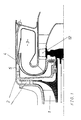
- the reference numeral 1 denotes a radial compressor which conveys combustion air into a combustion chamber 3 via guide wheels 2.
- a turbine 12 is arranged in the flow direction behind the combustion chamber 3.
- the fuel is atomized via atomizing nozzles 4.
- the atomizer nozzles 4 are arranged immediately behind the stator outlet 5 of the compressor 1.
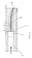
- the shape of the atomizing nozzles 4 can be seen from FIG.
- the atomizer nozzles 4 have a cavity 6 which tapers in the direction of flow and in which an atomizer member 7 is arranged.
- This atomizer member 7 includes a fuel supply line 8, a fuel channel 9 and a tear-off edge 10, the fuel channel 9 extending from the fuel supply line 8 and passing into the tear-off edge 10.
- the atomizer nozzles 4 are arranged directly behind the stator outlet 5 of the compressor 1. As a result, there is sufficient flow energy for atomizing fuel even when the gas turbine is started.
Landscapes
- Engineering & Computer Science (AREA)
- Chemical & Material Sciences (AREA)
- Combustion & Propulsion (AREA)
- Mechanical Engineering (AREA)
- General Engineering & Computer Science (AREA)
- Spray-Type Burners (AREA)
- Nozzles For Spraying Of Liquid Fuel (AREA)
Applications Claiming Priority (2)
| Application Number | Priority Date | Filing Date | Title |
|---|---|---|---|
| DE3942042 | 1989-12-20 | ||
| DE19893942042 DE3942042A1 (de) | 1989-12-20 | 1989-12-20 | Brennkammer fuer eine gasturbine mit luftunterstuetzten brennstoffzerstaeuberduesen |
Publications (1)
| Publication Number | Publication Date |
|---|---|
| EP0433868A1 true EP0433868A1 (fr) | 1991-06-26 |
Family
ID=6395873
Family Applications (1)
| Application Number | Title | Priority Date | Filing Date |
|---|---|---|---|
| EP90123970A Withdrawn EP0433868A1 (fr) | 1989-12-20 | 1990-12-12 | Chambre de combustion pour une turbine à gaz avec des atomisateurs de carburant assistés par air |
Country Status (2)
| Country | Link |
|---|---|
| EP (1) | EP0433868A1 (fr) |
| DE (1) | DE3942042A1 (fr) |
Cited By (2)
| Publication number | Priority date | Publication date | Assignee | Title |
|---|---|---|---|---|
| EP0540162A1 (fr) * | 1991-09-23 | 1993-05-05 | General Electric Company | Système d'injection pour chambre de combustion |
| US5265425A (en) * | 1991-09-23 | 1993-11-30 | General Electric Company | Aero-slinger combustor |
Families Citing this family (13)
| Publication number | Priority date | Publication date | Assignee | Title |
|---|---|---|---|---|
| DE19860583A1 (de) * | 1998-12-29 | 2000-07-06 | Abb Alstom Power Ch Ag | Brennkammer für eine Gasturbine |
| US7854112B2 (en) | 2004-12-01 | 2010-12-21 | United Technologies Corporation | Vectoring transition duct for turbine engine |
| US7976272B2 (en) | 2004-12-01 | 2011-07-12 | United Technologies Corporation | Inflatable bleed valve for a turbine engine |
| EP1825113B1 (fr) | 2004-12-01 | 2012-10-24 | United Technologies Corporation | Boîte de vitesses contre-rotative pour moteur à turbine en bout |
| US8096753B2 (en) | 2004-12-01 | 2012-01-17 | United Technologies Corporation | Tip turbine engine and operating method with reverse core airflow |
| US7845157B2 (en) | 2004-12-01 | 2010-12-07 | United Technologies Corporation | Axial compressor for tip turbine engine |
| US7934902B2 (en) | 2004-12-01 | 2011-05-03 | United Technologies Corporation | Compressor variable stage remote actuation for turbine engine |
| US8024931B2 (en) | 2004-12-01 | 2011-09-27 | United Technologies Corporation | Combustor for turbine engine |
| WO2006059977A1 (fr) | 2004-12-01 | 2006-06-08 | United Technologies Corporation | Moteur a turbine de bout et procede de mise en oeuvre correspondant |
| WO2006060000A1 (fr) | 2004-12-01 | 2006-06-08 | United Technologies Corporation | Ensemble aubes de guidage d'admission de soufflante variable, turbomachine dotee d'un tel ensemble et procede de commande correspondant |
| US8561383B2 (en) | 2004-12-01 | 2013-10-22 | United Technologies Corporation | Turbine engine with differential gear driven fan and compressor |
| EP1828591B1 (fr) | 2004-12-01 | 2010-07-21 | United Technologies Corporation | Foyer peripherique pour moteur a turbine de bout |
| US7980054B2 (en) | 2004-12-01 | 2011-07-19 | United Technologies Corporation | Ejector cooling of outer case for tip turbine engine |
Citations (2)
| Publication number | Priority date | Publication date | Assignee | Title |
|---|---|---|---|---|
| DE2223093A1 (de) * | 1972-05-12 | 1973-11-22 | Gen Electric | Brenner und brennstoffinjektor |
| FR2363001A2 (fr) * | 1976-08-30 | 1978-03-24 | Snecma | Chambre de combustion antipollution |
Family Cites Families (5)
| Publication number | Priority date | Publication date | Assignee | Title |
|---|---|---|---|---|
| GB1048968A (en) * | 1964-05-08 | 1966-11-23 | Rolls Royce | Combustion chamber for a gas turbine engine |
| GB1139004A (en) * | 1966-02-28 | 1969-01-08 | Mini Of Technology | Improvements in or relating to combustion devices |
| US4081957A (en) * | 1976-05-03 | 1978-04-04 | United Technologies Corporation | Premixed combustor |
| GB2161914B (en) * | 1980-12-10 | 1986-06-11 | Rolls Royce | Combustion equipment for a gas turbine engine |
| DE3819899C1 (en) * | 1988-06-11 | 1989-11-30 | Daimler-Benz Aktiengesellschaft, 7000 Stuttgart, De | Apparatus for generating a homogeneous mixture from a first and second medium |
-
1989
- 1989-12-20 DE DE19893942042 patent/DE3942042A1/de not_active Withdrawn
-
1990
- 1990-12-12 EP EP90123970A patent/EP0433868A1/fr not_active Withdrawn
Patent Citations (2)
| Publication number | Priority date | Publication date | Assignee | Title |
|---|---|---|---|---|
| DE2223093A1 (de) * | 1972-05-12 | 1973-11-22 | Gen Electric | Brenner und brennstoffinjektor |
| FR2363001A2 (fr) * | 1976-08-30 | 1978-03-24 | Snecma | Chambre de combustion antipollution |
Non-Patent Citations (1)
| Title |
|---|
| PATENT ABSTRACTS OF JAPAN, Band 9, Nr. 226 (M-412)[1949], 12. September 1985; & JP-A-60 82 724 (KOGYO GIJUTSUIN) 10-05-1985 * |
Cited By (2)
| Publication number | Priority date | Publication date | Assignee | Title |
|---|---|---|---|---|
| EP0540162A1 (fr) * | 1991-09-23 | 1993-05-05 | General Electric Company | Système d'injection pour chambre de combustion |
| US5265425A (en) * | 1991-09-23 | 1993-11-30 | General Electric Company | Aero-slinger combustor |
Also Published As
| Publication number | Publication date |
|---|---|
| DE3942042A1 (de) | 1991-06-27 |
Similar Documents
| Publication | Publication Date | Title |
|---|---|---|
| DE60122414T2 (de) | Verbrennungssystem für eine Gasturbine | |
| EP0681099B1 (fr) | Centrale à turbine à gaz | |
| DE3889539T2 (de) | Gasturbinenbrennkammer mit tangentialer brennstoffeinspritzung und zusätzlichen treibstrahlen. | |
| DE3942042A1 (de) | Brennkammer fuer eine gasturbine mit luftunterstuetzten brennstoffzerstaeuberduesen | |
| DE102009019978A1 (de) | Reinluftstrombrennstoffeinspritzeinrichtung | |
| EP0770175B1 (fr) | Dispositif d'injection de carburant destine a un moteur a combustion interne | |
| DD205959A5 (de) | Luft- oder gemischverdichtender verbrennungsmotor | |
| DE3873281T2 (de) | Wasser-spray-auswerfer-system fuer motoren mit dampfeinspritzung. | |
| DE2456837C3 (de) | Brennkammer für Brennkraftmaschinen, insbesonder aufgeladene Dieselmotoren | |
| DE1426423C3 (de) | Gasturbinenstrahltriebwerk in Dreistrom- und Mehrwellenbauart | |
| WO2020126848A1 (fr) | Module de groupe motopropulseur et procédé de fonctionnement | |
| DE2163537A1 (de) | Verfahren zum aufheizen von abgasreinigungsanlagen | |
| EP0468083A1 (fr) | Procédé de traitement du gaz de travail dans une turbine à gaz | |
| DE102013002999A1 (de) | Brennkraftrnaschine | |
| DE69019538T2 (de) | Gasturbine mit Injektor für gasförmigen Brennstoff und Injektor für eine derartige Gasturbine. | |
| DE3203558A1 (de) | Kraftstoffeinspritzvorrichtung mit nebenluftsystem | |
| EP1262637A1 (fr) | Méthode et dispositif pour une centrale de turbine à gaz | |
| WO2004065779A2 (fr) | Systeme d'injection pour moteur a combustion interne | |
| DE2411510A1 (de) | Brennkammer mit kombinierter einspritzund verdampferduese | |
| DE3544653A1 (de) | Brennstoffzufuhrsystem | |
| EP1375867B1 (fr) | Procédé de refroidissement intermédiaire et turbine à gaz avec refroidissement intermédiaire | |
| DE2133600A1 (de) | Starthilfe fur Dieselmaschinen | |
| EP0844387B1 (fr) | Dispositif et procédé pour l'injection de combustible à assistance pneumatique | |
| DE968568C (de) | Gasturbine mit Rotationszerstaeuber | |
| DE4310508A1 (de) | Triebwerk |
Legal Events
| Date | Code | Title | Description |
|---|---|---|---|
| PUAI | Public reference made under article 153(3) epc to a published international application that has entered the european phase |
Free format text: ORIGINAL CODE: 0009012 |
|
| AK | Designated contracting states |
Kind code of ref document: A1 Designated state(s): FR GB IT |
|
| 17P | Request for examination filed |
Effective date: 19910528 |
|
| STAA | Information on the status of an ep patent application or granted ep patent |
Free format text: STATUS: THE APPLICATION HAS BEEN WITHDRAWN |
|
| 17Q | First examination report despatched |
Effective date: 19930709 |
|
| 18W | Application withdrawn |
Withdrawal date: 19930706 |