EP0433953A2 - Lentille F theta et dispositif de balayage l'utilisant - Google Patents
Lentille F theta et dispositif de balayage l'utilisant Download PDFInfo
- Publication number
- EP0433953A2 EP0433953A2 EP90124475A EP90124475A EP0433953A2 EP 0433953 A2 EP0433953 A2 EP 0433953A2 EP 90124475 A EP90124475 A EP 90124475A EP 90124475 A EP90124475 A EP 90124475A EP 0433953 A2 EP0433953 A2 EP 0433953A2
- Authority
- EP
- European Patent Office
- Prior art keywords
- lens
- plane
- main scan
- optical system
- positive power
- Prior art date
- Legal status (The legal status is an assumption and is not a legal conclusion. Google has not performed a legal analysis and makes no representation as to the accuracy of the status listed.)
- Granted
Links
Images


Classifications
-
- G—PHYSICS
- G02—OPTICS
- G02B—OPTICAL ELEMENTS, SYSTEMS OR APPARATUS
- G02B13/00—Optical objectives specially designed for the purposes specified below
- G02B13/0005—Optical objectives specially designed for the purposes specified below having F-Theta characteristic
Definitions
- the present invention relates to an f ⁇ lens used in a scanning optical system, and more particularly to an f ⁇ lens for forming a fine spot and a laser scanning optical system using the same.
- a laser beam emitted by a laser light source is collimated by a collimater lens, reflected by a deflector such as a polygon mirror, and a laser beam spot is formed on an image plane by a focusing lens system and it is scanned.
- a so-called f ⁇ lens system having an f ⁇ characteristic (a theoretical image height is given by f ⁇ where f is a focal distance of the optical system and ⁇ is an incident angle) is used as a focusing lens in order to maintain the constant speed in a main scan direction on the image plane.
- an anamorphic optical system such as toric lens is sometimes used in the focusing lens.
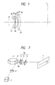
- a concave spherical lens 51, a convex spherical lens 52 and a toric lens 53 are arranged in the order from a mirror plane M of a deflector to an image plane I.
- Ri is a radius of curvature of the i-th lens plane as counted from the mirror plane M of the deflector
- Di is a plane-to-plane distance from the i-th lens plane to the (i+1)th lens plane
- Ni is a refractive index of a medium behind the i-th lens plane.
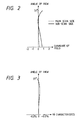
- FIG. 1 The image plane distortion of the f ⁇ lens shown in Fig. 1 and the f ⁇ characteristic are shown in Figs. 2 and 3.
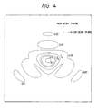
- a spot shape on the image plane at an image angle of 37 degrees is shown in Fig. 4.
- the f ⁇ characteristic and the image plane distortion are well compensated in the present example but the spot shapes of 1/e2 (spot shapes from the peak intensity to 1/e2 intensity) are triangular and good spot shape is not attained.
- spot shapes of 1/e2 spot shapes from the peak intensity to 1/e2 intensity
- a three-lens f ⁇ lens including a toric lens is provided.
- the first lens as viewed from a light incident side is one having a negative power in a main scan plane
- a second lens is one having a positive power in the main scan plane
- the third lens is one having a tornic plane and a positive power in the main scan plane.
- an air lens formed between the first lens and the second lens has a positive power in the main scan plane.
- Fig. 1 shows a main scan sectional view in a prior art system
- Fig. 2 shows an image plane distortion in the prior art system
- Fig. 3 shows an f ⁇ characteristic in the prior art system
- Fig. 4 shows a spot shape at an image angle of 37 degrees in the prior art
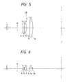
- Fig. 5 shows a main scan sectional view in a first embodiment
- Fig. 6 shows a sub-scan sectional view in the first embodiment
- Fig. 7 shows a scanning optical system which uses the f ⁇ lens of the present invention
- Fig. 8 shows an image plane distortion in the first embodiment
- Fig. 9 shows an f ⁇ characteristic in the first embodiment
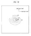
- Fig. 10 shows a spot shape at an image angle of 37 degrees in the first embodiment
- Fig. 10 shows a spot shape at an image angle of 37 degrees in the first embodiment
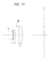
- FIG. 11 shows a main scan sectional view of a second embodiment
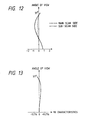
- Fig. 12 shows an image plane distortion in the second embodiment
- Fig. 13 shows an f ⁇ characteristic in the second embodiment
- Fig. 14 shows a spot shape at an image angle of 37 degrees in the second embodiment
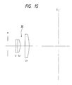
- Fig. 15 shows a main scan sectional view of a third embodiment
- Fig. 16 shows an image plane distortion in the third embodiment
- Fig. 17 shows an f ⁇ characteristic in the third embodiment
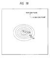
- Fig. 18 shows a spot shape at an image angle of 37 degrees in the third embodiment.
- Figs. 5 and 6 show a first embodiment of the present invention.
- Fig. 5 shows a sectional view of an f ⁇ lens of the present invention, taken along a main scan plane (which is formed by a light beam to be scanned and includes an optical axis)
- Fig. 6 shows a sectional view of the f ⁇ lens taken along a sub-scan plane (which is orthogonal to the main scan plane and includes the optical axis).
- the f ⁇ lens 10 comprises a concave spherical lens L1, a convex spherical lens L2 and a toric lens L3 arranged in this sequence as viewed from a mirror plane position M of a deflector to an image plane I.
- a symbol c denotes a cylindrical lens arranged between a light source such as a laser and the mirror plane position M. It has a power only in a sub-scan direction.
- r1 and r2 denote radii of curvature of a first plane and a second plane (counted from M) of the concave spherical lens L1
- r3 and r4 denote radii of curvature of a third plane and a fourth plane of the convex spherical lens L2
- r51 and r61 denote radii of curvature, in the main scan sectional plane, of a fifth plane and a sixth plane of the toric lens L3
- r52 and r62 denote radii of curvature, in the sub-scan sectional plane, of the fifth plane and the sixth plane.
- Fig. 7 shows a construction of a scanning optical system which uses the f ⁇ lens of the present invention. It comprises a light source unit 1 including a light source or the light source and a collimeter lens, a linear image focusing system 2 having a cylindrical lens for linearly focusing a light beam emitted from the light source unit 1, and a deflector 3 having a deflecting reflection plane 3a arranged in a vicinity of a position at which the light beam is linearly focused by the linear image focusing system 2.
- a spherical concave single lens 4 Arranged between the deflector 3 and a medium 7 to be scanned are a spherical concave single lens 4, a spherical convex single lens 5 and a single lens 6 having a toric plane which has a main axis and a sub-axis of different defraction powers in two orthogonal directions.
- a focused spot is formed on the medium 7 by the combined system of those lenses and the medium 7 is scanned by the spot as the deflector 3 is rotated.
- the f ⁇ lens 10 having the skew correction function comprises the spherical concave single lens 4, the spherical convex single lens 5 and the single lens 6 having the toric plane, as described above.
- the laser beam emitted from the light source is collimated by the collimeter lens 10, linearly directed to the vicinity of the mirror plane M of the deflector through the cylinder lens, deflected thereby and focused onto the image plane I.
- the laser beam is focused on the mirror plane M of the deflector by the cylindrical lens in the sub-scan sectional plane, and then focused again by the f ⁇ lens onto the image plane I.
- an air lens is formed between the lenses L1 and L2 by the second plane (radius of curvature r2) and the third plane (radius of curvature r3), where r3 ⁇ r2 ⁇ 0 (that is, r2/r3 ⁇ 1). Accordingly, the air lens has a positive power.
- the fact that the air lens has the positive power means that a combined power of the planes r2 and r3 is positive.
- the image plane distortion and the f ⁇ characteristic of the f ⁇ lens 10 are shown in Figs. 8 and 9. It is seen that the image plane distortion and the f ⁇ characteristic in the main scan plane and the sub-scan plane are good.
- Fig. 10 shows the result of calculation of a spot shape at an image angle of 37 degrees by using the f ⁇ lens 10.
- the spot is elliptic (a little longer on a sub-scan plane) at a contour line of 1/e2 , and it is keep of good shape.
- Fig. 11 shows a sectional view of a second embodiment of the present invention, taken along the main scan plane.
- An f ⁇ lens 20 comprises a concave spherical lens L1, a convex spherical lens L2 and a toric lens L3, arranged in this order as viewed from a mirror plane M.
- an air lens between the lenses L1 and L2 also has a positive power in the main scan plane.
- An f ⁇ lens 30 comprises a concave spherical lens L1, a convex spherical lens L2 and a toric lens L3, arranged in this order as viewed from a mirror plane M.
- r2 r3 ⁇ 0 (that is, r2/r3 ⁇ 1) is met and the air lens between the lenses L1 and L2 has a positive power.
- the f ⁇ lens of the present invention which is used in the scanning optical system and has the skew correction function has the first lens, the second lens and the third lens arranged in this order as viewed from the deflection plane.
- the first lens has a negative power in the main scan plane
- the second lens has a positive power in the main scan plane
- the third lens has a toric plane and a positive power is the main scan plane
- the air lens between the first lens and the second lens has a positive power in the main scan plane.
- the first lens is a concave spherical lens
- the second lens is a convex spherical lens
- the third lens is a toric lens.
- An f ⁇ lens having a skew correction function for use in a scanning optical system comprises a first lens having a negative power in a main scan plane, a second lens having a positive power in the main scan plane and arranged next to the first lens, a third lens having a toric plane and a positive power in the main scan plane and arranged next to the second lens, and an air lens formed between the first lens and the second lens having a positive power in the main scan plane.
Landscapes
- Physics & Mathematics (AREA)
- General Physics & Mathematics (AREA)
- Optics & Photonics (AREA)
- Lenses (AREA)
- Mechanical Optical Scanning Systems (AREA)
Applications Claiming Priority (2)
| Application Number | Priority Date | Filing Date | Title |
|---|---|---|---|
| JP1330648A JP2673591B2 (ja) | 1989-12-20 | 1989-12-20 | fθレンズ及びそれを用いたレーザー走査光学系 |
| JP330648/89 | 1989-12-20 |
Publications (3)
| Publication Number | Publication Date |
|---|---|
| EP0433953A2 true EP0433953A2 (fr) | 1991-06-26 |
| EP0433953A3 EP0433953A3 (en) | 1992-03-11 |
| EP0433953B1 EP0433953B1 (fr) | 1995-04-05 |
Family
ID=18235018
Family Applications (1)
| Application Number | Title | Priority Date | Filing Date |
|---|---|---|---|
| EP90124475A Expired - Lifetime EP0433953B1 (fr) | 1989-12-20 | 1990-12-17 | Lentille F theta et dispositif de balayage l'utilisant |
Country Status (4)
| Country | Link |
|---|---|
| US (1) | US5136412A (fr) |
| EP (1) | EP0433953B1 (fr) |
| JP (1) | JP2673591B2 (fr) |
| DE (1) | DE69018401T2 (fr) |
Cited By (2)
| Publication number | Priority date | Publication date | Assignee | Title |
|---|---|---|---|---|
| EP1376195A1 (fr) * | 2002-06-26 | 2004-01-02 | Dainippon Screen Mfg. Co., Ltd. | Dispositif de balayage optique |
| CN117139829A (zh) * | 2023-09-15 | 2023-12-01 | 南京波长光电科技股份有限公司 | 一种可用于fs飞秒激光下的大幅面扫描圆斑镜头 |
Families Citing this family (10)
| Publication number | Priority date | Publication date | Assignee | Title |
|---|---|---|---|---|
| JPH0545602A (ja) * | 1991-08-20 | 1993-02-26 | Hitachi Koki Co Ltd | レ−ザ走査装置 |
| KR960032037A (ko) * | 1995-02-25 | 1996-09-17 | 김광호 | 광주사장치 |
| US7333121B2 (en) * | 2005-04-28 | 2008-02-19 | Marvell International Technology Ltd | System and method for scaling data to compensate for slanted scanning in a bidirectional scanning laser printer |
| DE602008005340D1 (de) * | 2007-09-07 | 2011-04-14 | Givaudan Sa | Dimethylcyclohexyl-derivate als mittel zur neutralisation unangenehmer gerüche |
| CN101369047B (zh) * | 2008-04-28 | 2010-12-08 | 深圳市大族激光科技股份有限公司 | 光学镜头 |
| CN101324696B (zh) * | 2008-04-28 | 2011-05-04 | 深圳市大族激光科技股份有限公司 | 光学镜头 |
| CN101414047B (zh) * | 2008-04-28 | 2010-06-09 | 深圳市大族激光科技股份有限公司 | 光学镜头 |
| CN100593742C (zh) * | 2008-04-28 | 2010-03-10 | 深圳市大族激光科技股份有限公司 | 光学镜头 |
| CN104769474B (zh) * | 2012-10-31 | 2017-03-29 | 大族激光科技产业集团股份有限公司 | 一种远红外激光加工用Fθ镜头及激光加工设备 |
| CN108717226B (zh) * | 2018-08-08 | 2024-07-26 | 深圳市吉斯迪科技有限公司 | 一种激光医用f-theta光学镜头 |
Family Cites Families (7)
| Publication number | Priority date | Publication date | Assignee | Title |
|---|---|---|---|---|
| JPS60100118A (ja) * | 1983-11-05 | 1985-06-04 | Canon Inc | 倒れ補正機能を有する走査光学系 |
| JPS60153017A (ja) * | 1984-01-23 | 1985-08-12 | Asahi Optical Co Ltd | 大口径f・θレンズ |
| JPH0782157B2 (ja) * | 1986-01-24 | 1995-09-06 | 株式会社リコー | 面倒れ補正機能をもつ走査光学系 |
| JPH0627904B2 (ja) * | 1986-02-06 | 1994-04-13 | 旭光学工業株式会社 | レーザービームの走査光学系 |
| JPH0646258B2 (ja) * | 1986-02-28 | 1994-06-15 | 株式会社三協精機製作所 | 広角fθレンズ系 |
| JP2511904B2 (ja) * | 1986-09-22 | 1996-07-03 | 松下電器産業株式会社 | 光ビ−ム走査装置 |
| JPH02285321A (ja) * | 1989-04-26 | 1990-11-22 | Minolta Camera Co Ltd | 高精度トーリックfθレンズ系 |
-
1989
- 1989-12-20 JP JP1330648A patent/JP2673591B2/ja not_active Expired - Fee Related
-
1990
- 1990-12-14 US US07/627,585 patent/US5136412A/en not_active Expired - Lifetime
- 1990-12-17 DE DE69018401T patent/DE69018401T2/de not_active Expired - Fee Related
- 1990-12-17 EP EP90124475A patent/EP0433953B1/fr not_active Expired - Lifetime
Cited By (3)
| Publication number | Priority date | Publication date | Assignee | Title |
|---|---|---|---|---|
| EP1376195A1 (fr) * | 2002-06-26 | 2004-01-02 | Dainippon Screen Mfg. Co., Ltd. | Dispositif de balayage optique |
| US6771429B2 (en) | 2002-06-26 | 2004-08-03 | Dainippon Screen Mfg. Co., Ltd. | Optical scanner |
| CN117139829A (zh) * | 2023-09-15 | 2023-12-01 | 南京波长光电科技股份有限公司 | 一种可用于fs飞秒激光下的大幅面扫描圆斑镜头 |
Also Published As
| Publication number | Publication date |
|---|---|
| DE69018401T2 (de) | 1995-08-31 |
| JPH03191316A (ja) | 1991-08-21 |
| EP0433953B1 (fr) | 1995-04-05 |
| JP2673591B2 (ja) | 1997-11-05 |
| US5136412A (en) | 1992-08-04 |
| DE69018401D1 (de) | 1995-05-11 |
| EP0433953A3 (en) | 1992-03-11 |
Similar Documents
| Publication | Publication Date | Title |
|---|---|---|
| KR900006819B1 (ko) | 광학 시스템 | |
| EP0851261B1 (fr) | Appareil de balayage optique | |
| US4123135A (en) | Optical system for rotating mirror line scanning apparatus | |
| US4674825A (en) | Scanning optical system | |
| EP0242120B1 (fr) | Système de balayage lumineux | |
| US4818046A (en) | Light beam scanning device | |
| EP0433953B1 (fr) | Lentille F theta et dispositif de balayage l'utilisant | |
| US4695132A (en) | Fθ single lens | |
| US5095383A (en) | Optical unit for use in a laser beam printer or the like | |
| US4984858A (en) | Light beam scanning optical system | |
| KR100335624B1 (ko) | 레이저빔주사장치 | |
| JPH0727123B2 (ja) | 面倒れ補正走査光学系 | |
| US5153767A (en) | F-θ lens system and laser scanner using the same | |
| EP0658787B1 (fr) | Objectif de balayage et système optique de balayage utilisant un tel objectif | |
| JP3339934B2 (ja) | f・θレンズ | |
| EP0629891B1 (fr) | Système de balayage optique | |
| US6670980B1 (en) | Light-scanning optical system | |
| EP0444603A2 (fr) | Système de balayage optique | |
| EP0018787A1 (fr) | Dispositif de balayage optique | |
| JPH04141619A (ja) | 面倒れ補正機能を有する走査光学系 | |
| KR19980039051A (ko) | 주사광학장치 | |
| JP3266350B2 (ja) | fθレンズおよび光走査装置 | |
| JP2743176B2 (ja) | 光走査装置 | |
| JPH0417926Y2 (fr) | ||
| JP3538273B2 (ja) | 走査レンズ |
Legal Events
| Date | Code | Title | Description |
|---|---|---|---|
| PUAI | Public reference made under article 153(3) epc to a published international application that has entered the european phase |
Free format text: ORIGINAL CODE: 0009012 |
|
| 17P | Request for examination filed |
Effective date: 19910102 |
|
| AK | Designated contracting states |
Kind code of ref document: A2 Designated state(s): DE FR GB IT |
|
| PUAL | Search report despatched |
Free format text: ORIGINAL CODE: 0009013 |
|
| AK | Designated contracting states |
Kind code of ref document: A3 Designated state(s): DE FR GB IT |
|
| 17Q | First examination report despatched |
Effective date: 19931111 |
|
| GRAA | (expected) grant |
Free format text: ORIGINAL CODE: 0009210 |
|
| AK | Designated contracting states |
Kind code of ref document: B1 Designated state(s): DE FR GB IT |
|
| REF | Corresponds to: |
Ref document number: 69018401 Country of ref document: DE Date of ref document: 19950511 |
|
| ITF | It: translation for a ep patent filed | ||
| ET | Fr: translation filed | ||
| PLBE | No opposition filed within time limit |
Free format text: ORIGINAL CODE: 0009261 |
|
| STAA | Information on the status of an ep patent application or granted ep patent |
Free format text: STATUS: NO OPPOSITION FILED WITHIN TIME LIMIT |
|
| 26N | No opposition filed | ||
| REG | Reference to a national code |
Ref country code: GB Ref legal event code: IF02 |
|
| PGFP | Annual fee paid to national office [announced via postgrant information from national office to epo] |
Ref country code: FR Payment date: 20071210 Year of fee payment: 18 Ref country code: GB Payment date: 20071212 Year of fee payment: 18 |
|
| PGFP | Annual fee paid to national office [announced via postgrant information from national office to epo] |
Ref country code: DE Payment date: 20071213 Year of fee payment: 18 Ref country code: IT Payment date: 20071228 Year of fee payment: 18 |
|
| GBPC | Gb: european patent ceased through non-payment of renewal fee |
Effective date: 20081217 |
|
| REG | Reference to a national code |
Ref country code: FR Ref legal event code: ST Effective date: 20090831 |
|
| PG25 | Lapsed in a contracting state [announced via postgrant information from national office to epo] |
Ref country code: DE Free format text: LAPSE BECAUSE OF NON-PAYMENT OF DUE FEES Effective date: 20090701 |
|
| PG25 | Lapsed in a contracting state [announced via postgrant information from national office to epo] |
Ref country code: GB Free format text: LAPSE BECAUSE OF NON-PAYMENT OF DUE FEES Effective date: 20081217 |
|
| PG25 | Lapsed in a contracting state [announced via postgrant information from national office to epo] |
Ref country code: FR Free format text: LAPSE BECAUSE OF NON-PAYMENT OF DUE FEES Effective date: 20081231 |
|
| PG25 | Lapsed in a contracting state [announced via postgrant information from national office to epo] |
Ref country code: IT Free format text: LAPSE BECAUSE OF NON-PAYMENT OF DUE FEES Effective date: 20081217 |