EP0434041A1 - Polarisierendes Beleuchtungsgerät - Google Patents
Polarisierendes Beleuchtungsgerät Download PDFInfo
- Publication number
- EP0434041A1 EP0434041A1 EP90124803A EP90124803A EP0434041A1 EP 0434041 A1 EP0434041 A1 EP 0434041A1 EP 90124803 A EP90124803 A EP 90124803A EP 90124803 A EP90124803 A EP 90124803A EP 0434041 A1 EP0434041 A1 EP 0434041A1
- Authority
- EP
- European Patent Office
- Prior art keywords
- polarized
- plane
- beam splitter
- optical system
- polarized component
- Prior art date
- Legal status (The legal status is an assumption and is not a legal conclusion. Google has not performed a legal analysis and makes no representation as to the accuracy of the status listed.)
- Granted
Links
- 230000003287 optical effect Effects 0.000 claims abstract description 106
- 230000005855 radiation Effects 0.000 claims abstract description 36
- 238000006243 chemical reaction Methods 0.000 claims abstract description 34
- 230000010287 polarization Effects 0.000 claims abstract description 34
- 239000010408 film Substances 0.000 description 59
- 229910052782 aluminium Inorganic materials 0.000 description 20
- XAGFODPZIPBFFR-UHFFFAOYSA-N aluminium Chemical compound [Al] XAGFODPZIPBFFR-UHFFFAOYSA-N 0.000 description 20
- 239000004973 liquid crystal related substance Substances 0.000 description 18
- 238000009826 distribution Methods 0.000 description 15
- 230000003595 spectral effect Effects 0.000 description 14
- 238000005286 illumination Methods 0.000 description 13
- 230000008901 benefit Effects 0.000 description 9
- 230000005540 biological transmission Effects 0.000 description 8
- 239000006185 dispersion Substances 0.000 description 8
- 239000003086 colorant Substances 0.000 description 6
- 238000000034 method Methods 0.000 description 6
- 239000013078 crystal Substances 0.000 description 5
- 238000010521 absorption reaction Methods 0.000 description 4
- 238000002834 transmittance Methods 0.000 description 4
- 230000000694 effects Effects 0.000 description 3
- 239000012788 optical film Substances 0.000 description 3
- 230000001105 regulatory effect Effects 0.000 description 3
- 239000011358 absorbing material Substances 0.000 description 2
- 230000015572 biosynthetic process Effects 0.000 description 2
- 230000008859 change Effects 0.000 description 2
- 230000001276 controlling effect Effects 0.000 description 2
- 230000006872 improvement Effects 0.000 description 2
- 239000000463 material Substances 0.000 description 2
- 229910052751 metal Inorganic materials 0.000 description 2
- 239000002184 metal Substances 0.000 description 2
- 230000009467 reduction Effects 0.000 description 2
- 238000000926 separation method Methods 0.000 description 2
- 239000010409 thin film Substances 0.000 description 2
- 235000010627 Phaseolus vulgaris Nutrition 0.000 description 1
- 244000046052 Phaseolus vulgaris Species 0.000 description 1
- 238000002835 absorbance Methods 0.000 description 1
- 230000006866 deterioration Effects 0.000 description 1
- 230000002708 enhancing effect Effects 0.000 description 1
- 239000011521 glass Substances 0.000 description 1
- 229910052736 halogen Inorganic materials 0.000 description 1
- 150000002367 halogens Chemical class 0.000 description 1
- 239000007788 liquid Substances 0.000 description 1
- 238000004519 manufacturing process Methods 0.000 description 1
- 230000028161 membrane depolarization Effects 0.000 description 1
- 229910001507 metal halide Inorganic materials 0.000 description 1
- 150000005309 metal halides Chemical class 0.000 description 1
- 230000007935 neutral effect Effects 0.000 description 1
- 230000008569 process Effects 0.000 description 1
- 230000007480 spreading Effects 0.000 description 1
- 238000003892 spreading Methods 0.000 description 1
- 238000003786 synthesis reaction Methods 0.000 description 1
Images


Classifications
-
- H—ELECTRICITY
- H04—ELECTRIC COMMUNICATION TECHNIQUE
- H04N—PICTORIAL COMMUNICATION, e.g. TELEVISION
- H04N9/00—Details of colour television systems
- H04N9/12—Picture reproducers
- H04N9/31—Projection devices for colour picture display, e.g. using electronic spatial light modulators [ESLM]
- H04N9/3141—Constructional details thereof
- H04N9/315—Modulator illumination systems
- H04N9/3167—Modulator illumination systems for polarizing the light beam
-
- G—PHYSICS
- G02—OPTICS
- G02B—OPTICAL ELEMENTS, SYSTEMS OR APPARATUS
- G02B27/00—Optical systems or apparatus not provided for by any of the groups G02B1/00 - G02B26/00, G02B30/00
- G02B27/28—Optical systems or apparatus not provided for by any of the groups G02B1/00 - G02B26/00, G02B30/00 for polarising
- G02B27/283—Optical systems or apparatus not provided for by any of the groups G02B1/00 - G02B26/00, G02B30/00 for polarising used for beam splitting or combining
-
- H—ELECTRICITY
- H04—ELECTRIC COMMUNICATION TECHNIQUE
- H04N—PICTORIAL COMMUNICATION, e.g. TELEVISION
- H04N9/00—Details of colour television systems
- H04N9/12—Picture reproducers
- H04N9/31—Projection devices for colour picture display, e.g. using electronic spatial light modulators [ESLM]
- H04N9/3102—Projection devices for colour picture display, e.g. using electronic spatial light modulators [ESLM] using two-dimensional electronic spatial light modulators
- H04N9/3105—Projection devices for colour picture display, e.g. using electronic spatial light modulators [ESLM] using two-dimensional electronic spatial light modulators for displaying all colours simultaneously, e.g. by using two or more electronic spatial light modulators
-
- G—PHYSICS
- G02—OPTICS
- G02F—OPTICAL DEVICES OR ARRANGEMENTS FOR THE CONTROL OF LIGHT BY MODIFICATION OF THE OPTICAL PROPERTIES OF THE MEDIA OF THE ELEMENTS INVOLVED THEREIN; NON-LINEAR OPTICS; FREQUENCY-CHANGING OF LIGHT; OPTICAL LOGIC ELEMENTS; OPTICAL ANALOGUE/DIGITAL CONVERTERS
- G02F1/00—Devices or arrangements for the control of the intensity, colour, phase, polarisation or direction of light arriving from an independent light source, e.g. switching, gating or modulating; Non-linear optics
- G02F1/01—Devices or arrangements for the control of the intensity, colour, phase, polarisation or direction of light arriving from an independent light source, e.g. switching, gating or modulating; Non-linear optics for the control of the intensity, phase, polarisation or colour
- G02F1/13—Devices or arrangements for the control of the intensity, colour, phase, polarisation or direction of light arriving from an independent light source, e.g. switching, gating or modulating; Non-linear optics for the control of the intensity, phase, polarisation or colour based on liquid crystals, e.g. single liquid crystal display cells
- G02F1/133—Constructional arrangements; Operation of liquid crystal cells; Circuit arrangements
- G02F1/1333—Constructional arrangements; Manufacturing methods
- G02F1/1335—Structural association of cells with optical devices, e.g. polarisers or reflectors
- G02F1/133528—Polarisers
- G02F1/133536—Reflective polarizers
-
- G—PHYSICS
- G02—OPTICS
- G02F—OPTICAL DEVICES OR ARRANGEMENTS FOR THE CONTROL OF LIGHT BY MODIFICATION OF THE OPTICAL PROPERTIES OF THE MEDIA OF THE ELEMENTS INVOLVED THEREIN; NON-LINEAR OPTICS; FREQUENCY-CHANGING OF LIGHT; OPTICAL LOGIC ELEMENTS; OPTICAL ANALOGUE/DIGITAL CONVERTERS
- G02F1/00—Devices or arrangements for the control of the intensity, colour, phase, polarisation or direction of light arriving from an independent light source, e.g. switching, gating or modulating; Non-linear optics
- G02F1/01—Devices or arrangements for the control of the intensity, colour, phase, polarisation or direction of light arriving from an independent light source, e.g. switching, gating or modulating; Non-linear optics for the control of the intensity, phase, polarisation or colour
- G02F1/13—Devices or arrangements for the control of the intensity, colour, phase, polarisation or direction of light arriving from an independent light source, e.g. switching, gating or modulating; Non-linear optics for the control of the intensity, phase, polarisation or colour based on liquid crystals, e.g. single liquid crystal display cells
- G02F1/133—Constructional arrangements; Operation of liquid crystal cells; Circuit arrangements
- G02F1/1333—Constructional arrangements; Manufacturing methods
- G02F1/1335—Structural association of cells with optical devices, e.g. polarisers or reflectors
- G02F1/133528—Polarisers
- G02F1/13355—Polarising beam splitters [PBS]
-
- G—PHYSICS
- G02—OPTICS
- G02F—OPTICAL DEVICES OR ARRANGEMENTS FOR THE CONTROL OF LIGHT BY MODIFICATION OF THE OPTICAL PROPERTIES OF THE MEDIA OF THE ELEMENTS INVOLVED THEREIN; NON-LINEAR OPTICS; FREQUENCY-CHANGING OF LIGHT; OPTICAL LOGIC ELEMENTS; OPTICAL ANALOGUE/DIGITAL CONVERTERS
- G02F1/00—Devices or arrangements for the control of the intensity, colour, phase, polarisation or direction of light arriving from an independent light source, e.g. switching, gating or modulating; Non-linear optics
- G02F1/01—Devices or arrangements for the control of the intensity, colour, phase, polarisation or direction of light arriving from an independent light source, e.g. switching, gating or modulating; Non-linear optics for the control of the intensity, phase, polarisation or colour
- G02F1/13—Devices or arrangements for the control of the intensity, colour, phase, polarisation or direction of light arriving from an independent light source, e.g. switching, gating or modulating; Non-linear optics for the control of the intensity, phase, polarisation or colour based on liquid crystals, e.g. single liquid crystal display cells
- G02F1/133—Constructional arrangements; Operation of liquid crystal cells; Circuit arrangements
- G02F1/1333—Constructional arrangements; Manufacturing methods
- G02F1/1335—Structural association of cells with optical devices, e.g. polarisers or reflectors
- G02F1/1336—Illuminating devices
- G02F1/13362—Illuminating devices providing polarized light, e.g. by converting a polarisation component into another one
Definitions
- the present invention relates to an image display apparatus.
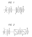
- Fig. 1 is a schematic view showing the principal structure of an example of the conventional image display apparatus.
- Said display apparatus is provided with a light source 1 composed for example of a halogen lamp or a metal halide lamp; a mirror 2 reflecting a part of the light emitted by said light source 1; a heat ray cut-off filter 3 for absorbing or reflecting the heat ray in the light entering directly from the light source 1 or indirectly from the mirror 2; a condenser lens 4 for converting the light, after removal of the heat ray, into a parallel beam; a polarizer 5 for converting said parallel light beam into linearly polarized light; a liquid crystal light valve 7 for modulating said linearly polarized light according to an image signal; a polarizer 8 for transmitting only a component, parallel to the transmission axis thereof, of said modulated linearly polarized light; and a projection lens 10 for projecting the linearly polarized light, transmitted by said polarizer 8, in a magnified scale onto an unrepresented screen.
- a light source 1 composed for example of a halogen lamp or a metal halide lamp
- Fig. 2 is a schematic view showing the principal part of another example of such conventional projection display apparatus.
- Said apparatus is equipped with two polarizing beam splitters 6, 9 respectively in front of and behind the light crystal light valve 7, in place for the two polarizers 5, 8 in the apparatus shown in Fig. 1.
- the projection display apparatus shown in Figs. 1 and 2 are associated with a drawback that the efficiency of ulitization of light does not exceed 50 %, since, within the light emitted by the light source 1, a linearly polarized component transmitted by the polarizing beam splitter 6 alone is utilized for illuminating the light crystal light valve 7 while the perpendicularly polarized component is lost.
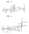
- Fig. 3 shows a projection display apparatus disclosed in the Japanese Patent Application Laid-Open No. 61-90584 for rectifying said drawback.
- the parallel light beam emerging from the condenser lens 4 enters a polarizing beam splitter 11, and the P-polarized component L p is transmitted by the functional plane (an evaporated film formed on a diagonal plane between two rectangular prisms) 11a of said polarizing beam splitter 11, while the S-polarized component L s is perpendicularly reflected to enter a total reflection prism 12. Being perpendicularly reflected again in said prism 12, the S-polarized component L s emerges from said prism 12 in a direction same as that of the P-polarized component L p .
- the S-polarized component L s is polarized in a direction parallel to the functional plane 11a of the polarizing beam splitter 11, and the P-polarized component L p is polarized in a direction perpendicular to that of the S-polarized component.
- a ⁇ /2-phase shifting plate 13 whereby said S-polarized component L2 is subjected to a rotation of the polarizing direction by 90° and is converted into a P-polarized component L p *.
- wedge-shaped lenses 14, 15 for light path deflection, whereby the P-polarized component L p transmitted by said polarizing beam splitter 11 and the P-polarized component L p * converted by the ⁇ /2-phase shifting plate 13 are subjected to light path deflection and mutually cross at a point P0 on the entrance face of the liquid crystal light valve 7, thereby providing a synthesized light.
- Such projection display apparatus can illuminate the liquid crystal light valve 7 with both the S-polarized component L s and the P-polarized component L p separated by the polarizing beam splitter 11 and can therefore double the efficiency of light utilization in comparison with the apparatus shown in Fig. 2.
- the object of the present invention is to provide an image display apparatus equipped with an improved polarized illuminating device capable of reducing the loss in the amount of light.
- an image display apparatus comprising: a radiation source; a generator for generating an image by modulating a polarized light beam; and directing means for directing a light beam from said radiation source toward said generator; wherein said directing means has a conversion optical system for converting the beam from said radiation source into said polarized light beam; said conversion optical system comprises a polarizing beam splitter for splitting the beam from said radiation source into a first beam and a second beam whose polarization planes are orthogonal to each other; and an arrangement of a 1/4 wavelength plate and a mirror for rotating the polarization plane of said first beam to generate a third beam whose polarization plane is same as that of the second beam; whereby said third beam is directed toward said generator through said polarizing beam splitter while said second beam is also directed toward said generator.
- an image display apparatus comprising: a radiation source; a generator for generating an image by modulating a polarized light beam; and directing means for directing a light beam from said radiation source toward said generator; wherein said directing means comprises a collimator for substantially collimating the beam from said radiation source and a conversion optical system for converting thus collimated beam into said polarized beam; and said conversion optical system comprises a polarizing beam splitter with a splitting plane inclined to the optical axis of said collimator, for splitting said collimated beam by transmitting a P-polarized beam thereof while reflecting an S-polarized beam thereof; an arrangement of a 1/4 wavelength plate and a mirror for rotating the polarization plane of said S-polarized beam to generate a polarized beam with a polarized plane coinciding with that of said P-polarized beam and directing said generated polarized beam toward a predetermined direction through said polarizing beam split
- an image display apparatus comprising: a radiation source; a generator for generating an image by modulating a polarized light beam; and directing means for directing a light beam from said radiation source toward said generator; wherein said directing means comprises a collimator for substantially collimating the beam from said radiation source and a conversion optical system for converting thus collimated beam into said polarized beam; and said conversion optical system comprises a first polarizing beam splitter with a splitting plane inclined to the optical axis of said collimator, for splitting said collimated beam by transmitting a P-polarized beam thereof while reflecting an S-polarized beam thereof in a predetermined direction; a second polarizing beam splitter with a splitting plane inclined to the optical axis of said collimator; and an arrangement of a 1/4 wavelength plate and a mirror for receiving said P-polarized beam through said second polarizing beam splitter, rotating the polarization plane of said P-
- an image display apparatus comprising: a radiation source; a generator for generating an image by modulating a polarized light beam; and directing means for directing a light beam from said radiation source toward said generator; wherein said directing means comprises a collimator for substantially collimating the beam from said radiation source and a conversion optical system for converting thus collimated beam into said polarized beam; and said conversion optical system comprises a polarizing beam splitter with a splitting plane inclined to the optical axis of said collimator, for splitting said collimated beam by transmitting a P-polarized beam thereof into a predetermined direction while reflecting an S-polarized beam thereof; an arrangement of a 1/4 wavelength plate and a mirror for rotating the polarization plane of said S-polarized beam to generate a polarized beam with a polarization plane coinciding with that of said P-polarized beam and directing said generated polarized beam toward said polarizing beam split
- Fig. 1 is a schematic view showing the structure of an example of the conventional projection display apparatus
- Fig. 2 is a schematic view showing the structure of another example of the conventional projection display apparatus
- Fig. 3 is a schematic view showing the structure of a projection display apparatus disclosed in the Japanese Patent Application Laid-Open No. 61-90584
- Fig. 4 is a schematic view showing a drawback encountered when the parallel illumination method is employed in the projection display apparatus shown in Fig. 3
- Fig. 5 is a view of a first embodiment of the polarized illuminating apparatus of the present invention
- Fig. 6 is a schematic view showing the optical path in the polarized illuminating apparatus shown in Fig. 5;
- Fig. 1 is a schematic view showing the structure of an example of the conventional projection display apparatus
- Fig. 2 is a schematic view showing the structure of another example of the conventional projection display apparatus
- Fig. 3 is a schematic view showing the structure of a projection display apparatus disclosed in the Japanese Patent Application Laid-
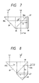
- FIG. 7 is a view of a second embodiment of the polarized illuminating apparatus of the present invention
- Fig. 8 is a view of a third embodiment of the polarized illuminating apparatus of the present invention
- Fig. 9 is a view of a fourth embodiment of the polarized illuminating apparatus of the present invention
- Fig. 10 is a partial view of an embodiment of a projection display apparatus provided with the polarized illuminating apparatus shown in Fig. 9
- Figs. 11A and 11B are respectively a lateral view and a plan view of an embodiment of a projection display apparatus provided with the polarized illuminating apparatus shown in Fig. 5;
- FIG. 12 is a view of the basic structure of a fifth embodiment of the polarized illuminating apparatus of the present invention
- Fig. 13 is a schematic view of the optical path of the polarized illuminating apparatus shown in Fig. 12
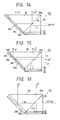
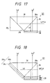
- Figs. 14 to 17 are views showing the details of sixth to ninth embodiments of the polarized illuminating apparatus of the present invention
- Figs. 18 and 19A to 19C are respectively a view and charts showing a tenth embodiment of the polarized illuminating apparatus of the present invention
- Figs. 20, 21, 22, 23A and 23B are views showing still other embodiments of the present invention.
- Fig. 5 is a schematic view of a first embodiment of the polarized illuminating apparatus of the present invention
- Fig. 6 is a view showing the optical path thereof.
- Said polarized illuminating apparatus is composed of a polarizing beam splitter 26 having a function plane (an evaporated film formed on a diagonal plane at which two rectangular prisms are mutually adhered) for transmitting the P-polarized component L p of a parallel light beam emerging from a condenser lens 4 while rectangularly reflecting the S-polarized component L s ; a total relfection prism 29 provided with a total reflection plane 29a contacting at an end thereof rectangularly with an end of the functional plane 26a of said polarizing beam splitter 26 and serving to rectangularly reflect said transmitted P-polarized component L p ; a ⁇ /4 phase shifting plate 27 contacting at an end thereof, at an angle of 45°, with an end of the functional plane 26a of said polarizing beam splitter and with an end of the total reflection plane 29a of said total reflection prism 29, and adapted to receive said reflected S-polarized component L s ; and a reflecting plate 28 having a reflecting plane, composed of an aluminum evaporated film or an optical
- the parallel light beam emerging from the condenser lens 4 is split into the P-polarized component L p and the S-polarized component L s , by respective transmission and rectangular reflection by the functional plane 26a of the polarizing beam splitter 26.
- Said reflected S-polarized component L s enters the ⁇ /4 phase shifting plate 27, then reflected by the reflecting plane of the reflecting plate 28, and is again transmitted by the phase shifting plate 27, thereby subjected to a rotation of the plane of polarization by 90° and thereby converted into a P-polarized component L p *, which is transmitted by the functional plane 26a and emerges from the polarizing beam splitter 26.
- said transmitted P-polarized component L p is rectangularly reflected by the total reflection plane 29a of the total reflection prism 29, and emerges therefrom parallel to said converted P-polarized component L p *.
- the P-polarized component L p energing from the total reflection prism 29 and the converted P-polarized component L p * emerging from the polarizing beam splitter 26 are mutually symmetrical in the vertical direction. Consequently, even if the light beam entering the polarizing beam splitter 26 becomes unbalanced due for example to a positional shift of the light source 1, there will result no abrupt change in the illumination intensity at the junction point of said P-polarized component L p and said converted P-polarized component L p *. Also since said P-polarized component L p and said converted P-polarized component L p * have a same optical path length, there can be prevented an imbalance in the illumination intensity resulting from uncollimated light.
- a ray obliquely entering the ⁇ /4 phase shifting plate 27, such as ⁇ in Fig. 6, may be lost by transmission or reflection by said phase shifting plate 27, but such loss can be prevented by forming, on the junction plane between the polarizing beam splitter 26 and the ⁇ /4 shifting plate 27, an optical multi-layered film which reflects a ray of a large incident angle, such as ⁇ , and transmits the normal ray with a small incident angle.
- an incident ray entering the total reflection plane 29a of the prism 29 with an incident angle smaller than the total reflection angle, such as ⁇ shown in Fig. 6, is partially lost in said P-polarized component L p due to partial transmission, but such loss can also be prevented by forming a multi-layered reflecting film or a metal reflecting film on the total reflection plane 29a.
- the present polarized illuminating apparatus can improve the efficiency of light utilization, as the P-polarized component L p and the S-polarized component L s split by the polarizing beam splitter 26 can both be utilized for illuminating the light valve (not shown). Besides a remarkable improvement can be achieved in the balance of illumination intensity which has been a problem in the parallel illumination of the liquid crystal light valve (not shown) with said P-polarized component L p and said converted P-polarized component L p *, and there is also achieved a reduction in the distance between the polarized illuminating apparatus and the light valve, which has been difficult to achieve in the illuminating system with the synthesized light shown in Fig. 3.
- the present invention enables compactization of the image display apparatus.
- the total reflection prism 29 may be integrally formed with a rectangular prism, positioned next to said total reflection prism 29, of the polarizing beam splitter 26.
- Fig. 7 illustrates a second embodiment of the polarized illuminating apparatus of the present invention.
- the present embodiment is different from that shown in Fig. 5 in that the P-polarized component L p , transmitted by the functional plane 36a of a polarizing beam splitter 36 and immediately emerges therefrom, while the S-polarized component L s reflected by said functional plane 36a is converted into a P-polarized component L p * by a ⁇ /4 phase shifting plate 37 and a reflecting plate 38, then rectangularly reflected by the total reflection plane 39a of a total reflection prism 39 and emerges therefrom in parallel manner to said P-polarized component L p .
- the direction of the emerging light can be made same as that of the incident light, without addition of other optical components.
- the P-polarized component and the converted P-polarized component L p * have mutually different optical path lengths, but can provide same advantages as those in the apparatus shown in Fig. 1.
- the total reflection prism 39 may be formed integrally with a rectangular prism, positioned next to said total reflection prism 39, of the polarizing beam splitter 36.
- Fig. 8 illustrates a third embodiment of the polarized illuminating apparatus of the present invention.
- the reflecting plate 28 in Fig. 5 is replaced by a rectangular prism 40, for reflecting the S-polarized component L s , reflected by the functional plane 46a of a polarizing beam splitter 46, without formation of an unnecessary polarized component.
- said S-polarized component L s is laterally inverted with respect to the central axis thereof, then enters a ⁇ /4 phase shifting plate 47 from the rectangular prism 40, and is converted into the P-polarized component L p *. Consequently said converted P-polarized component L p * and the P-polarized component L p emerging from a total reflection prism 49 lack the symmetry explained in the apparatus shown in Fig. 1, so that the illumination intensity distribution tends to become unbalanced when the light bean entering the polarizing beam splitter 46 is unbalanced.
- the P-polarized component L p emerging from the total reflection prism 49 and the converted P-polarized component L p * emerging from the polarizing beam splitter 46 have mutually different optical path lengths, so that the use of uncollimated light may pose a problem.
- the present embodiment provides other advantages same as those in the apparatus shown in Fig. 1.
- the total reflection prism 49 may be formed integrally with a rectangular prism, positioned next to said total reflection prism 49, of the polarizing beam splitter 46.
- Fig. 9 illustrates a fourth embodiment of the polarized illuminating apparatus of the present invention.
- the polarized illuminating apparatus of the present embodiment is composed of a polarizing beam splitter 56 having a first functional plane 56a (an evaporated film formed on one of two diagonal planes for jointing three rectangular prisms) for transmitting the P-polarized component L p of incident light beam and perpendicularly reflecting the S-polarized component thereof, and a second functional plane 56b (an evaporated film formed on the other of said two diagonal planes) contacting at an end thereof rectangularly with said first functional plane 56a; a ⁇ /4 phase shifting plate 57 contacting at an end thereof, with an angle of 45°, with the other end of said second functional plane and adhered to a face of the polarizing beam splitter 56 opposite to the entrance face thereof; and a reflecting plate 58 having a reflecting plane adhered to said ⁇ /4 phase shifting plate 57.
- a polarizing beam splitter 56 having a first functional plane 56a (an evaporated film formed on one of two diagonal planes for jointing three rectangular prisms) for transmitting the P-
- the S-polarized component L s is reflected by the first functional plane 56a of the polarizing beam splitter 56 and immediately emerges therefrom.
- the P-polarized component L p is transmitted by the first and second functional planes 56a, 56b of the polarizing beam splitter 56 and enters the ⁇ /4 phase shifting plate 57.
- Said component is converted into the S-polarized component L s * by a rotation of the plane of polarization by 90° in the phase shifting plate 57 and the reflecting plate 58, then perpendicularly reflected by the second functional plane 56b of the polarizing beam splitter 56, and emerges therefrom in a direction same as that of the above-mentioned S-polarized component L s .
- the present embodiment is not suitable for uncollimated light because said S-polarized component L s and said converted S-polarized component L s * have mutually different optical path lengths, but provide other advantages same as those in the apparatus shown in Fig. 5. Also the apparatus of the present embodiment may be utilized as an analyzer in an image display apparatus utilizing a liquid crystal light valve (as will be explained later), because of absence of the phase shifting plate 57 and the reflecting plate 58 at the side opposite to the entrance side.
- Fig. 10 is a schematic view showing the principal part of an embodiment of the projection display apparatus utilizing the polarized illuminating apparatus shown in Fig. 9.
- said projection display apparatus is provided with a light source unit 100 comprising a light source 1, a reflection mirror 2, a heat ray cut-off filter 3 and a condenser lens 4; a polarized illuminating apparatus 101 shown in Fig. 9; a cross dichroic prism 102 adhered at a face thereof to the exit face of said polarized illuminating apparatus 101 and bearing reflective liquid crystal light valves 65R, 65G, 65B for red, green and blue colors respectively on other three faces; and a projection lens 10 positioned opposed to the exit face of the polarized illuminating apparatus 101.
- the S-polarized component L s is perpendicularly reflected by a first functional plane 56a of a polarizing beam splitter 56 constituting the polarized illuminating apparatus 101 (cf. Fig. 9), and enters the cross dichroic prism 102.
- the P-polarized component L p is converted into an S-polarized component L s * by the ⁇ /4 phase shifting plate 57 and the reflecting plate 58 as explained before, then perpendicularly reflected by the second functional plane 56b of the polarizing beam splitter 56 (cf. Fig. 9) and enters the cross dichroic prism 102.
- said white parallel light beam is directed to the cross dichroic prism 102 after conversion into a linearly polarized beam, consisting of the S-polarized components L s , L s * , in the polarized illuminating apparatus 101.
- Said linearly polarized beam is split by the cross dichroic prism 102 into red, green and blue light beams R, G, B, which are respectively projected toward the reflective liquid crystal light valves 65R, 65G, 65B for red, green and blue colors.
- the liquid crystal used in said light valves is of ECB (electrically controlled birefringence) type or 45° TN (twisted nematic) type, and has a property of rotating the plane of polarization of the incident light, depending on the voltage applied according to image signals. Consequently, the light incident to the reflective light crystal light valves 65R, 65G, 65B is linearly polarized light composed of S-polarized components, but the reflected light contains a P-polarized component according to the image signal in each pixel.
- the reflected light beams are synthesized in the cross dichroic prism 102 and return to the polarized illuminating apparatus 101.
- a pair of functional planes of the polarizing beam splitter 56 (Fig. 9) function as an analyzer, whereby the P-polarized component L po in said synthesized reflected light is transmitted and projected onto a screen (not shown) through the projection lens 10.
- a part of the S-polarized component L so in said synthesized reflected light, entering the first functional plane 56a of the polarizing beam splitter 56 is perpendicularly reflected by said functional plane 56a and returns to the light source unit 100.
- the above-explained projection display apparatus provides advantages of improving the efficiency of light utilization since the white parallel light beam from the light source unit 100 can be converted, without loss, into a linearly polarized beam by the polarized illuminating apparatus 100, and significantly reducing the rear-focus length of the projection lens in comparison with that in the conventional projection display apparatus, because of separation and synthesis of beams of different colors by means of the cross dichroic prism 102, thereby expanding the design freedom of the projection lens 10 and compactizing the entire display apparatus.
- the polarized illuminating apparatus 101 can be utilized as an analyzer.
- Figs. 11A and 11B are respectively a side view and a plan view of an embodiment of the projection display apparatus utilizing the polarized illuminating apparatus shown in Fig. 5.
- This projection display apparatus is provided with a light source unit 100; a polarized illuminating apparatus 111 shown in Fig. 5; a mirror 77 for perpendicularly reflecting the light beam from said polarized illuminating apparatus 111 downwards; a polarizing beam splitter 78 for perpendicularly reflecting the S-polarized component of the beam reflected by said mirror 77 toward the polarized illuminating apparatus 111 while transmitting the P-polarized component; a cross dichroic prism 102 adhered on a lateral face thereof to the exit face of said S-polarized component of the polarized beam splitter 78 and having reflective liquid crystal light valves 65R, 65G, 65B for red, green and blue colors on three other lateral faces; and a projection lens 10 positioned opposite to the side of the cross dichroic prism 112 with respect to the polarized beam splitter 78.
- a white parallel light beam emitted from the light source unit 100 enters the polarized illuminating apparatus 111, and the P-polarized component of said white parallel beam and the converted P-polarized component obtained from the ⁇ /4 phase shifting plate 27 and the reflecting plate 28 (both P-polarized components being hereinafter collectively called P-polarized beam) enter the mirror 77. Said P-polarized beam is totally reflected by the mirror 77 and enters the polarizing beam splitter 78. As the plane of polarization of said P-polarized beam is S-polarized plane to the functional plane of the polarizing beam splitter 78, said beam is reflected by said plane and enters the cross dichroic prism 102.
- the P-polarized beam behaves in the same manner as in the cross dichroic prism shown in Fig. 10, and the reflected light beams, modulated by the reflective liquid crystal light valves 65R, 65G, 65B according to an image signal enter the polarizing beam splitter 78, which functions as an analyzer, as in the polarized illuminating apparatus 10 shown in Fig. 10.
- the components, transmitted by said polarizing beam splitter 78, of the reflected light beams are projected through the projection lens 10 onto a screen (not shown) to form an image thereon.
- the projection display apparatus of the present embodiment provides, as in the apparatus shown in Fig. 10, advantages of improvement in the efficiency of light utilization, expansion of design freedom of the projection lens 10, and compactization of the entire structure.
- the present embodiment employs the polarized illuminating apparatus shown in Fig. 5, but the apparatus shown in Fig. 7 or 8 may naturally be employed likewise.
- the projection display apparatus employing a transmission liquid crystal light valve as shown in Fig. 3 may be obtained by combining the polarized illuminating apparatus of the present invention shown in Fig. 5, 7, 8 or 9 with the wedge-shaped lenses 14, 15 shown in Fig. 3. Also in the projection display apparatus shown in Fig. 1 or 2, the polarized illuminating apparatus of the present invention may be positioned between the condenser lens 4 and the polarizing plate 5, or between the condenser lens 4 and the polarizing beam splitter.
- the polarized illuminating apparatus explained in the foregoing has the advantage of improving the efficiency of light utilization, by emitting either of the P- and S-polarized components, separated by a polarizing beam splitter, of the incident light beam and also the other component after rotation of the plane of polarization by 90° with a ⁇ /4 phase shifting plate and a reflecting member. Consequently the present invention enables to obtain an image display apparatus capable of brighter display.
- the polarizing beam splitter is usually so designed that the reflected S-polarized light and the transmitted P-polarized light are best separated at an incident angle of 45° to the functional plane.
- a high transmittance for the P-polarized component is obtained by selecting the refractive index of the multi-layered film constituting said functional plane so as to satisfy Brewster's law (Angle), but a decrease in transmittance is inevitable for any ray entering with an incident angle not matching the Brewster's low. Consequently, if a spreading light beam enters the functional plane, the reflected light contains the P-polarized component and the light beam emerging from the optical phase shifting plate contains the S-polarized component, so that the intensity of the light beam emerging from the polarizing beam splitter inevitably diminishes.
- optical phase shifting plate is unable to provide a phase difference of ⁇ /2 or ⁇ /4 in the entire wavelength range, because of its wavelength dependence (dispersion), so that the emerging light inevitably contains the S-polarized component.
- a pair of light beams of a same direction of polarization emerging from said apparatus may not be mutually equal in the intensity, giving rise to an uneven intensity distribution of the illuminating light.
- said light beams may be mutually different in spectral distribution, so that the color of illuminating light may vary depending on the position of illumination.
- a polarized illuminating apparatus capable of suppressing the unevenness in the intensity distribution or the spectral distribution of the illuminating light, and a projection display apparatus utilizing such polarized illuminating apparatus.
- an optical filter is employed for rectifying the unevenness in the intensity of said paired light beams.
- Said optical filter is inserted in either or both of the light paths of said P- and S-polarized components and serves to attenuate the intensity of the incident light.
- Said optical filter can be of various types, such as a reflective filter for reflecting the incident light with simultaneous attenuation of intensity, a transmissive filter for transmitting the incident light with simultaneous attenuation of intensity, or a filter for absorbing the incident light.
- said paired light beams can be given substantially equal spectral distributions, by suitably regulating the wavelength characteristics of said optical filter.
- the optical filter to be employed in the present invention is for example composed of a multi-layered optical film or an ordinary color absorbing filter. In the former, desired characteristics can be obtained by regulating the material and thickness of said multi-layered optical film.
- the aforementioned polarizing beam splitter can be suitably designed to rectify the unevenness in the intensity between said paired light beams.
- the intensity ratio of said P- and S-polarized components can be varied by the adjustment on the optical thin film constituting the functional plane (light splitting plane) of said polarizing beam splitter, the unevenness in the intensity of said paired light beams, resulting from the dispersion of the phase shifting plate, may be rectified by such method.
- the optical components such as mirrors and prisms, for defining the optical paths of said P-and S-polarized components, may be given a function of the above-mentioned optical filter, in order to rectify the unevenness in the intensity of the paired light beams.
- said mirror is composed of a reflective filter with a multi-layered optical thin film.
- a light absorbing material is mixed in the material for said component at the manufacture thereof.
- the polarized illuminating apparatus is provided with a polarizing beam splitter for splitting the incident light beam into a first P-polarized component and a first S-polarized component; a ⁇ /4 phase shifting plate positioned in contact with an end of the functional plane of said polarizing beam splitter and adapted to receive said first P-polarized component and said first S-polarized component; and a reflective member for reflecting the first P-polarized component or the first S-polarized component transmitted by said ⁇ /4 phase shifting plate toward said phase shifting plate, wherein the first P-polarized component or the first S-polarized component is converted respectively into a second S-polarized component or a second P-polarized component by said ⁇ /4 phase shifting plate and said reflective member, and said first and second P-polarized components or said first and second S-polarized components are emitted from the apparatus, comprising at least a single optical filter positioned in contact with an end of the functional plane of said polarizing beam splitter and adapted to effect transmission, reflection
- the polarized illuminating apparatus is provided with a polarizing beam splitter with a functional plane for transmitting the P-polarized component of the incident light beam and perpendicularly reflecting the S-polarized component thereof; a reflective member positioned in contact at an end thereof perpendicularly to an end of the functional plane of said polarizing beam splitter and perpendicularly reflecting said transmitted P-polarized component; a ⁇ /4 phase shifting plate positioned in contact at an end thereof, with an angle of 45°, with an end of the functional plane of said polarizing beam splitter and in contact with an end of the reflecting surface of said reflective member, and receiving said reflected S-polarized component; and a reflective plate with a reflective plane position close to said ⁇ /4 phase shifting plate, wherein said reflected S-polarized component is converted into a P-polarized component by said ⁇ /4 phase shifting plate and said reflective plate, and said converted P-polarized component and said transmitted P-polarized component are emitted from the apparatus, comprising
- either one of the P- and S-polarized components split by the polarizing beam splitter is introduced into the ⁇ /4 phase shifting plate and the reflective member to rotate the plane of polarization by 90° to coincide with that of the other component, whereby the incident light beam can be fully utilized by the emission of both polarized components.
- no ray can enter the ⁇ /4 phase shifting plate without passing the functional plane of the polarizing beam splitter or can re-enter said functional plane without passing the ⁇ /4 phase shifting plate.
- the S-polarized component reflected by the functional plane of the polarizing beam splitter contains a considerable amount of P-polarized component resulting from non-perpendicularly incident rays, and the converted P-polarized component obtained by the ⁇ /4 phase shifting plate and the reflective member also contains a considerable amount of S-polarized component because said ⁇ /4 phase shifting plate cannot provide a phase difference of ⁇ /4 over the entire wavelength range, but the reflectance for the S-polarized component of the polarizing beam splitter can be made close to 100 % for both perpendicularly and non-perpendicularly incident rays.
- the two emitted P-polarized components may mutually differ in intensity or in color, based on the characteristics of the polarizing beam splitter, particularly the incident angle dependence of the transmittance of the P-polarized component, the spectral dispersion of the ⁇ /4 phase shifting plate, the reflection loss of the reflective plane contacting said phase shifting plate, the reflection loss of the reflective plane for perpendicularly reflecting the P-polarized component transmitted by said polarizing beam splitter etc.
- optical filter positioned in contact with an end of the functional plane of the polarizing beam splitter enables correction on intensity and/or color independently on the two emitted P-polarized components without generating light leakage, so that no overall unevenness nor local variation in the central area in the illumination intensity or color is encountered even in the parallel illumination system.
- Fig. 12 is a view of a fifth embodiment of the polarized illuminating apparatus of the present invention
- Fig. 13 is a schematic view showing the optical path thereof.
- Said polarized illuminating apparatus 121 is provided with a polarizing beam splitter 26 having a functional plane (an evaporated film formed on a diagonal plane where two rectangular prisms are adhered) for transmitting the P-polarized component L p of a parallel beam emerging from a condenser lens 4 while perpendicularly reflecting the S-polarized component L s thereof; a prism 30 positioned in contact at an end thereof perpendicularly with an end of the functional plane (light splitting plane) 26 of the polarizing beam splitter, and having a reflective plane 30a which is provided with an optical filter and reflects perpendicularly said transmitted P-polarized component L p ; a ⁇ /4 phase shifting plate 27 positioned in contact at an end thereof, with an angle of 45°, with an end of the functional plane 26a of the polarizing beam splitter 26 and in contact with an end of the reflective plane 30a of the prism 30 and receiving said reflected S-polarized component L s ; and a reflective plate 28 having a
- the polarizing beam splitter 26 is so selected as to be capable of splitting the polarized components over the entire visible wavelength range, particularly with a high reflectance for the S-polarized component, and the ⁇ /4 phase shifting plate 27 is composed of an optical crystal capable of providing a phase difference of ⁇ /4 at the approximate center of the wavelength range to be used.
- the reflective plate 28 is provided with a reflective plane composed of an aluminum evaporated film.
- the reflective plane 30a is provided, as will be explained later, in succession from the side of beam splitter 26, with an aluminum evaporated film and an absorbing filter showing a weak absorption on a part, particularly red and blue regions, of the incident light.
- the parallel beam emerging from the condenser lens 4 is split into the P-polarized component L p and the S-polarized component L s by transmissin and perpendicular reflection, respectively, by the functional plane 26a of the polarizing beam splitter 26.
- Said reflected S-polarized component enters the ⁇ /4 phase shifting plate 27, then reflected by the reflective plane of the reflective plate 28 and again transmitted by said phase shifting plate 27, thereby being subjected to a rotation of the plane of polarization by 90° and thus converted into a P-polarized component L p *, which is transmitted by the functional plane 26a and emerges from the polarizing beam splitter.
- said transmitted P-polarized component L p is perpendicularly reflected by the reflective plane 30a of the prism 30 and emerges therefrom, parallel to said converted P-polarized component L p * but along a different light path.
- all the light beam entering the polarizing beam splitter 26 is received by the functional plane 26a thereof, as indicated by rays ⁇ 1, ⁇ 2, and ⁇ 3 in Fig. 13, and split into the P-polarized component L p and the S-polarized component L s .
- said S-polarized component L s is all received by the ⁇ /4 phase shifting plate 27 and is subjected to the rotation of plane of polarization. Inversely said P-polarized component never enters said phase shifting plate 27.
- said P-polarized component L p emitted from the prism 30 and said converted P-polarized component L p * emitted from the polarizing beam splitter 26 are mutually symmetrical in the vertical direction. Consequently an abrupt change in the illumination intensity can be prevented at the connection of the P-polarized component L p and the converted P-polarized component L p * even if the incident light beam to the polarizing beam splitter becomes unbalanced for example by a positional deviation of the light source 1.
- the structure of the present embodiment can provide a sufficiently high depolarization ratio in the emitted P-polarized light L p *.
- the intensity of said P-polarized component L p * is reduced to T ⁇ R times of that of said S-polarized components L s , wherein T is the rotation of plane of polarization in two passings (going and returning) through the phase shifting plate 27 while R is the reflectance of the reflective plate 28, so that the emitted P-polarized components L p , L p * become mutually different in intensity and in color.
- the reflective plane 30a may be given an attenuating effect for preventing such differences. Examples of the structure of such reflective plane are shown in Figs. 14 to 18, wherein same components as those in Fig. 12 are represented by same numbers.
- a reflective plane 29c composed of an aluminum evaporated film formed on the surface of the prism 30, and a light absorbing filter 29b.
- the P-polarized component L p transmitted by the polarizing beam splitter 26 is partially absorbed by the filter 29b, then perpendicularly reflected by the reflective plane 29c, again partially absorbed by the filter 29c and emitted as the P-polarized component L p ' of predetermined intensity and spectral distribution.
- the absorbance of the absorbing filter 29b for different wavelength components have to be so adjusted that both P-polarized components L p ' and L p * become mutually equal in intensity and in color (spectral distribution).
- half-reflecting planes (half mirrors) 29d, 29e composed for example of multi-layered optical films are formed stepwise on the diagonal faces of the prism 30.
- the P-polarized component L p transmitted by the polarizing beam splitter 26 is partially reflected by the half-reflecting planes 29d, but the remaining portion is transmitted. Said portion is perpendicularly reflected by a reflective plane 29c composed of an aluminum evaporated film and reaches the half-reflecting planes 29e.
- the portion reflected by the half-reflecting planes 29d is transmitted by the polarizing beam splitter 26 as a P-polarized component L p '''.
- the P-polarized component reaching the half-reflecting planes 29e is partially reflected, and the reflected portion returns to the half-reflecting planes 29d by way of the reflective plane 29c, while the remaining portion is transmitted by said half-reflecting planes 29c and is emitted as a P-polarized component L p '.
- the light reflected by the half-reflecting planes 29e and returning to the half-reflecting planes 29d is partially transmitted as the P-polarized component L p ''', and the remaining portion is again reflected and propagates towards the reflective plane 29c.
- the above-explained procedure is repeated whereby the P-polarized component is divided into L p ' and L p '''.
- the reflectance and transmittance of the half-reflecting planes 29d, 29e are to be so selected that the P-polarized components L p ' and L p * become mutually equal in intensity and color. Also in case only either of the half-reflecting planes 29d and 29e is employed, similar advantages can be expected by suitably selecting the reflectance and transmitance thereof.
- An area 29f, surrounded by the reflecting planes 29c, 29d and 29e, may also be filled (constituted) with glass of a predetermined reflective index, whereby it is rendered possible to utilize the total reflection at the interface with air and thus to dispense with the reflective plane 29c composed of aluminum evaporated film.
- a multi-layered film 29g and an absorbing film 29b for absorbing the light transmitted by the film 29g.
- the mutual optically adhesion of both films allows to regulate the structure of the film 29g thereby controlling the reflectance thereof to the P-polarized component L p in such a manner that the P-polarized component L p ' becomes equal to the p-polarized component L p *.
- an optical filter 29i which is an optical multi-layered film 29i formed on a reflective plane of the prism 30, and a prism 29j optically adhered to the film 29i.
- Said film 29i is so designed that the p-polarized components L p ' and L p * become mutually substantially equal in intensity and in color.
- the incident light to the polarizing beam splitter 26, if obliquely entering the ⁇ /4 phase shifting plate 27 as exemplified by a ray ⁇ in Fig. 13, may result in a loss in the intensity by transmission or absorption by said phase shifting plate 27.
- Such light loss can be prevented by forming, on the junction plane of the polarizing beam splitter 26 and the ⁇ /4 phase shifting plate 27, an optical multi-layered film which reflects a ray of a large incident angle, such as the ray ⁇ , but transmits the normal ray of a smaller incident angle.
- the present polarized illuminating apparatus 121 can improve the efficiency of light utilization, since both the P-polarized component L p and the S-polarized component L s , split by the polarizing beam splitter, can be utilized for illuminating the liquid crystal light valve (not shown). It can also drastically reduce the imbalance of illumination intensity distribution which has been a problem in the parallel illumination system with said P-polarized component L p and said converted P-polarized component L p *, and can achieve a reduction in the distance between the polarized illuminating apparatus and the liquid valve, a target difficult to achieve in the conventional illuminating system with synthesized light as shown in Fig. 3, thereby enabling to compactize the projection display apparatus employing the polarized illuminating apparatus 121 of the present invention.
- the prism 30 may be formed integrally with a rectangular prism, positioned adjacent to said prism 30, of the polarizing beam splitter.
- the optical filters are formed integrally on the prism 30, but such optical filter may naturally be formed separately. Also such optical filters may be provided in the optical path of the P-polarized component L p after emerging from the prism 30 and/or in the optical path of the P-polarized component L p * after emerging from the beam splitter 26.
- a filter for regulating the intensity only such as a neutral density (ND) filter. It is also possible to regulate the intensity with an ND filter and the color with a color filter, by positioning said filters in at least one of the optical paths for the P-polarized components L p , L p * .
- a color absorbing material may be mixed in the prism 30 or prisms constituting the beam splitter 26 to provide these components with a filter function.
- Fig. 18 shows still another embodiment of the present invention, wherein the structure other than the reflective plane 28 and 30a is same as that shown in the foregoing embodiments in Figs. 12 to 17 and will not, therefore, be explained.
- the ⁇ /4 phase shifting plate 27 is so designed as to provide a phase difference of ⁇ /4 in the green wavelength range.
- said phase shifting plate 27 has a function, in the green wavelength range, of rotating the plane of polarization by approximately 90° in two passages of the light, but in the red and blue wavelength ranges of which the central wavelengths are different by about 100 nm from that of said green wavelength range, the percentage of conversion from an incident polarized component to the orthogonally polarized component diminishes to about 90 %.
- the P-polarized component L p * reflected by the reflective plane 28 becomes weaker in intensity, by about 10 % in the red and blue wavelength ranges, than the P-polarized component L p ' reflected by the reflective plane 30a.
- the reflective plane 28 is composed, in succession from the side of the beam splitter 26, of a multi-layered film 28b and an aluminum evaporated film 28a. Also the reflective plane 30a is composed, from the side of the prism 30, of a multi-layered film 29k and an aluminum evaporated film 29c.
- the reflectance of aluminum in the visible wavelength range is about 90 % at highest.
- the reflectance of the multi-layered films 28b, 29k can be considerably arbitrarily selected with a range from 0 to 100 %, depending on the layer structure.
- a stable reflectance can be easily obtained with aluminum, independently from the thickness thereof, but, the multi-layered film requires a precisely controlled film forming process for obtaining stable reflective characteristics, as the reflectance depends greatly on the film thickness.
- each of the reflective planes 28, 30 is composed of a combination of a metal film, particularly an aluminum film, which can easily provide a stable reflectance despite of a certain reflection loss, and a multi-layered film which provides a larger freedom in the selection of reflectance, thereby enabling stable and delicate control of the difference of about 10 % in intensity and in color, between the P-polarized components L p ' and L p * resulting from the dispersion characteristics specific to the ⁇ /4 phase shifting plate, as will be explained more detailedly in the following.
- Figs. 19A, 19B and 19C respectively show the reflectance of an aluminum film, the reflectance of a multi-layered film, and the overall reflectance including the multiple reflections between both films, in the absence of mutual interference among the lights reflected by said films. A portion not reflected by the aluminum film is lost.
- the total reflectance R tot is determined as follows:
- the variation in the total reflectance R tot is several times to several tens of times smaller than that in the reflectance of the multi-layered film, so that the total reflectance R tot is affected little by a certain fluctuation in the reflectance of the multi-layered film.
- the multi-layered film has to be designed in consideration of the interference of the reflected lights from both films.
- the multi-layered film 28b is so designed as to provide the aluminum film 28a with a reflection enhancing function with little wavelength dependence in the visible range, thereby minimizing the reflection loss of the reflective plane 28.
- the multi-layered film 29k enhances the reflection of the aluminum film 29c strongly in the green wavelength region and weakly in the red and blue wavelength regions, thereby suppressing the imbalances in intensity and in color of the P-polarized components L p ' and L p * resulting from the influence of the phase shifting plate 27. This structure provides the highest efficiency of light utilization.
- the optical multi-layered film 28b provides the aluminum film 28a with reflection enhancement, weakly in the green wavelength region and strongly in the red and blue wavelength regions, thereby cancelling the characteristics of the ⁇ /4 phase shifting plate 27 and obtaining a P-polarized component L p * balanced in the intensity of red, green and blue colors.
- the multi-layered film 29k provides the aluminum 29c with a reflection enhancement with little wavelength dependence in the visible range, in such a manner that the P-polarized components L p ' and L p * become balanced in intensity and in color.
- Fig. 20 shows still another embodiment of the present invention, wherein shown are an absorptive or reflective color filter 31, and a total reflection plane 30a of the prism 30.
- the incident light enters a prism 26 from the right-hand side, and is separated by the functional plane 26a into the P-polarized (transmitted) component L p and the S-polarized (reflected) component L s .
- the P-polarized component is reflected by the reflective plane 30a, constituting an interface with air, of the prism 30 and emerges upwards.
- the S-polarized component is transmitted by the color filter 31, then converted into a P-polarized component by the rotation of plane of polarization by 90° in the ⁇ /4 phase shifting plate 27 and the reflective plate 28, again transmitted by the color filter 31 in the opposite direction, further transmitted by the functional plane 26a and emitted upwards.
- Said color filter 31 has such spectral characteristics as to correct the spectral distribution of the polarized component returning to the functional plane 26a after being converted in the ⁇ /4 phase shifting plate 27 and the reflective plate 28 to the spectral distribution of the P-polarized component L p . Consequently the P-polarized components L p , L p * have a same spectral distribution, or a same color.
- Fig. 21 shows still another embodiment of the present invention, in which a multi-layered reflective color filter 28 is provided in contact with the ⁇ /4 phase shifting plate 27.
- This embodiment effects correction of color (spectral distribution) when the S-polarized component coming from the plane 26a and through the phase shifting plate 27 is reflected by the reflective color filter 28.
- the spectral characteristics of said reflective color filter 28 is so selected that the spectral distributions of the P-polarized components L p and L p * become mutually equal, so that both components have a same color.
- Fig. 22 shows still another embodiment of the present invention.
- the polarized illuminating apparatus 121 of the present embodiment is different from that shown in Fig. 12 in that the P-polarized component L p transmitted by the functional plane 36a of the polarizing beam splitter 36 is immediately emitted therefrom, while the S-polarized component L s reflected by said functional plane 36a is converted into the P-polarized component L p * by the ⁇ /4 phase shifting plate 37 and the reflective plate 38, then perpendicularly reflected by the total reflection plane 39a of the total reflection prism 39 and is emitted therefrom, parallel to the aforementioned P-polarized component L p .
- Said P-polarized components L p , L p * are adjusted to a same color, by adding an absorptive or reflective optical filter explained above to the reflective plate 38 or the reflective plane 39a.
- the above-explained polarized illuminating apparatus 121 can match the direction of emitted beams with that of incident beam without the additional of other optical components.
- the apparatus of the present embodiment may be incompatible with the uncollimated light because the P-polarized component L p and said converted P-polarized component L p * have different optical path lengths, but provide other advantages same as those in the apparatus shown in Fig. 12.
- the total reflection prism 39 may be formed integrally with a rectangular prism, positioned adjacent to said total reflection prism, of the polarizing beam splitter 36.
- the unbalance in the intensities of the P-polarized components L p , L p * can be corrected by positioning an absorptive filter, such as an ND filter, in at least one of the optical paths of said components.
- the characteristics of the polarizing beam splitter may be suitably controlled to correct the intensity unevenness resulting from the dispersion by the phase shifting plate.
- Figs. 23A and 23B are respectively a side view and a plan view, showing the principal part of said embodiment.
- Said projection display apparatus is provided with a light source unit 110; a polarized illuminating apparatus 121 shown in one of Figs. 12 to 21; a mirror 77 for reflecting the light beam from said apparatus 121 perpendicularly downwards; a polarizing beam splitter 78 for perpendicularly reflecting the S-polarized component of the light beam reflected by said mirror 77 toward the polarized illuminating apparatus 121 while transmitting the P-polarized component of said light beam; a cross dichroic prism 112 adhered at a lateral face thereof to the emitting plane for said S-polarized component of said polarizing beam splitter 78 and bearing reflective liquid crystal light valves 75R, 75G, 75B for red, green and blue colors on other three lateral faces; and a projection lens 113 positioned at a side of said polarizing beam splitter 78 opposite to the cross dichroic prism 112.
- a parallel white light beam from the light source unit 100 enters the polarized illuminating apparatus 121 which emits to the mirror 77, as shown in Figs. 12 to 21, the P-polarized component of said white light beam and the P-polarized component converted by the ⁇ /4 phase shifting plate 27 and the reflective plate 28 of a same intensity (said P-polarized component and said converted P-polarized component being hereinafter collectively called P-polarized beams).
- Said P-polarized beams are totally reflected by the mirror 77 and enter the polarizing beam splitter 78.
- As said P-polarized beams have an S-polarized plane with respect to the functional plane of the polarizing beam splitter 78, they are reflected by said functional plane and enter the cross dichroic prism 112.
- Said P-polarized beams are modulated by the reflective liquid crystal light valves 75R, 75G, 75B, and the resulting beams enter the polarizing beam splitter 78, which functions as an analyzer, whereby the reflected components transmitted by said beam splitter 78 are projected onto a screen (not shown) through the projection lens 113, thereby forming an image on said screen.
- the correction has been directed to the unevenness in the intensity in a pair of illuminating light beams, resulting from the dispersion in a phase shifting plate, but additional correction may be incorporated in order to correct the unevenness resulting from the dispersion in the polarizing beam splitter.
- the phase shifting plate may be composed of an optical crystal, a film or a liquid crystal.
- An image display apparatus has a radiation source, generator for generating an image by modulating a polarized light beam and directing device for directing a light beam from the radiation source toward the generator.
- the directing device has a conversion optical system for converting the beam from the radiation source into the polarized light beam.
- the conversion optical system has a polarizing beam splitter for splitting the beam from the radiation source into a first and second beams.
- a 1/4 wavelength plate and a mirror are arranged so that the plane of polarization of the first beam is rotated to generate a third beam with the plane of polarization same as that of the second beam.
- the third beam is directed toward the generator through the polarizing beam splitter while the second beam is also directed toward the generator.
Landscapes
- Engineering & Computer Science (AREA)
- Multimedia (AREA)
- Signal Processing (AREA)
- Physics & Mathematics (AREA)
- General Physics & Mathematics (AREA)
- Optics & Photonics (AREA)
- Projection Apparatus (AREA)
Applications Claiming Priority (4)
| Application Number | Priority Date | Filing Date | Title |
|---|---|---|---|
| JP330033/89 | 1989-12-20 | ||
| JP1330033A JP2752751B2 (ja) | 1989-12-20 | 1989-12-20 | 表示装置 |
| JP192677/90 | 1990-07-20 | ||
| JP2192677A JPH0478816A (ja) | 1990-07-20 | 1990-07-20 | 偏光照明装置及び該偏光照明装置を備える投写型表示装置 |
Publications (2)
| Publication Number | Publication Date |
|---|---|
| EP0434041A1 true EP0434041A1 (de) | 1991-06-26 |
| EP0434041B1 EP0434041B1 (de) | 1996-09-11 |
Family
ID=26507467
Family Applications (1)
| Application Number | Title | Priority Date | Filing Date |
|---|---|---|---|
| EP90124803A Expired - Lifetime EP0434041B1 (de) | 1989-12-20 | 1990-12-19 | Polarisierendes Beleuchtungsgerät |
Country Status (3)
| Country | Link |
|---|---|
| US (1) | US5446510A (de) |
| EP (1) | EP0434041B1 (de) |
| DE (1) | DE69028497T2 (de) |
Cited By (12)
| Publication number | Priority date | Publication date | Assignee | Title |
|---|---|---|---|---|
| EP0457605A3 (en) * | 1990-05-18 | 1992-05-06 | Canon Kabushiki Kaisha | Polarization converting device and polarized-light illuminating system using the device and image display unit using the device |
| EP0470369A3 (en) * | 1990-08-08 | 1992-09-02 | Grundig E.M.V. Elektro-Mechanische Versuchsanstalt Max Grundig Hollaend. Stiftung & Co. Kg. | Projecting unit for large picture projection |
| EP0509630A3 (en) * | 1991-02-21 | 1993-07-14 | Eugene Dolgoff | A high efficiency light valve projection system |
| WO1993018620A3 (en) * | 1992-03-05 | 1993-10-28 | Rank Brimar Ltd | Spatial light modulator system |
| EP0584802A1 (de) * | 1992-08-26 | 1994-03-02 | Hughes Aircraft Company | Anordnung zur Umwandlung von unpolarisiertem in linear polarisiertes Licht |
| FR2696246A1 (fr) * | 1992-09-28 | 1994-04-01 | Sextant Avionique | Procédé et dispositif de projection d'une image en couleur résultant d'une modulation par valves optiques. |
| EP0615148A3 (de) * | 1993-03-08 | 1995-06-28 | Lueder Ernst | Verfahren und Vorrichtung zur Polarisation von Licht. |
| EP0704137A4 (de) * | 1993-03-31 | 1996-05-29 | Hughes Jvc Tech Corp | Farbprojektionssystem mit einer einzigen projektionslinse |
| US5535054A (en) * | 1992-03-11 | 1996-07-09 | Nikon Corporation | Illumination optical system |
| US5590942A (en) * | 1992-09-11 | 1997-01-07 | Canon Kabushiki Kaisha | Polarizing conversion unit, illuminating device and projector using them |
| EP0768800A1 (de) * | 1995-10-12 | 1997-04-16 | Sony Corporation | Farbprojektor |
| WO2000070880A1 (en) * | 1999-05-14 | 2000-11-23 | 3M Innovative Properties Company | Projection system with polymeric film optical components |
Families Citing this family (49)
| Publication number | Priority date | Publication date | Assignee | Title |
|---|---|---|---|---|
| US5903388A (en) | 1992-06-11 | 1999-05-11 | Sedlmayr Steven R | High efficiency electromagnetic beam projector and systems and method for implementation thereof |
| EP1257128B1 (de) * | 1993-03-16 | 2004-03-03 | Seiko Epson Corporation | Projektionsanzeigevorrichtung |
| DE4435450A1 (de) * | 1993-10-04 | 1995-04-06 | Matsushita Electric Industrial Co Ltd | Flüssigkristalleinheit und Projektionsanzeige unter Verwendung einer Flüssigkristalleinheit |
| US5576854A (en) * | 1993-11-12 | 1996-11-19 | Hughes-Jvc Technology Corporation | Liquid crystal light valve projector with improved contrast ratio and with 0.27 wavelength compensation for birefringence in the liquid crystal light valve |
| JPH07294850A (ja) * | 1994-04-22 | 1995-11-10 | Canon Inc | 照明装置及びそれを用いた投影装置 |
| KR100400114B1 (ko) * | 1994-06-01 | 2003-12-31 | 코닌클리케 필립스 일렉트로닉스 엔.브이. | 고효율조명디바이스및그러한디바이스를포함하는영상투영장치 |
| US5729306A (en) * | 1994-09-30 | 1998-03-17 | Sharp Kabushiki Kaisha | Light splitting and synthesizing device and liquid crystal display apparatus including the same |
| JP2738324B2 (ja) * | 1995-01-23 | 1998-04-08 | 日本電気株式会社 | 投写型液晶表示装置 |
| US5594591A (en) * | 1995-02-01 | 1997-01-14 | Pioneer Electronic Corporation | Prism system and a liquid crystal projection device |
| JP3417757B2 (ja) * | 1995-02-28 | 2003-06-16 | ペンタックス株式会社 | 液晶表示装置およびその光束分離方法 |
| KR0174852B1 (ko) * | 1995-04-18 | 1999-03-20 | 김주용 | 패널식 액정 전면 투영기용 광편향프리즘을 이용한 개선 광학계 |
| JPH09230321A (ja) * | 1996-02-20 | 1997-09-05 | Denso Corp | カラー液晶表示装置 |
| US5995284A (en) * | 1996-03-29 | 1999-11-30 | 3M Innovative Properties Company | Polarized illumination system for LCD projector |
| US5975703A (en) | 1996-09-30 | 1999-11-02 | Digital Optics International | Image projection system |
| US6005655A (en) * | 1996-10-31 | 1999-12-21 | Minolta Co., Ltd. | Projector capable of projecting polarized illumination light |
| JP3653907B2 (ja) * | 1996-12-24 | 2005-06-02 | ソニー株式会社 | プロジェクタ |
| US6257726B1 (en) | 1997-02-13 | 2001-07-10 | Canon Kabushiki Kaisha | Illuminating apparatus and projecting apparatus |
| JP3637743B2 (ja) * | 1997-10-15 | 2005-04-13 | ソニー株式会社 | 投射型液晶表示装置 |
| JP3661392B2 (ja) * | 1998-02-18 | 2005-06-15 | セイコーエプソン株式会社 | 偏光照明装置および投写型表示装置 |
| US6132047A (en) * | 1998-02-18 | 2000-10-17 | Seiko Epson Corporation | Polarized light illumination device and projector |
| US5900976A (en) * | 1998-02-20 | 1999-05-04 | Displaytech, Inc. | Display system including a polarizing beam splitter |
| JP2002508092A (ja) * | 1998-04-02 | 2002-03-12 | コーニンクレッカ フィリップス エレクトロニクス エヌ ヴィ | 増強された輝度を有する画像投射装置 |
| KR100609060B1 (ko) * | 1999-07-21 | 2006-08-09 | 삼성전자주식회사 | 광투사형 디스플레이장치의 편광변환소자 |
| AU2001281402A1 (en) | 2000-08-08 | 2002-02-18 | Fineground Networks | Method and system for parameterized web documents |
| US7047281B1 (en) | 2000-08-08 | 2006-05-16 | Fineground Networks | Method and system for accelerating the delivery of content in a networked environment |
| US7027224B2 (en) | 2001-01-31 | 2006-04-11 | Sharp Laboratories Of America, Inc. | Wave plate mounting |
| US7310687B2 (en) | 2001-03-23 | 2007-12-18 | Cisco Technology, Inc. | Methods and systems for managing class-based condensation |
| KR100534575B1 (ko) | 2001-04-24 | 2005-12-07 | 삼성에스디아이 주식회사 | 프로젝션시스템의 광전환장치 |
| US7343396B2 (en) | 2002-06-20 | 2008-03-11 | Fineground Networks | Precomputation of web documents |
| TWI289708B (en) | 2002-12-25 | 2007-11-11 | Qualcomm Mems Technologies Inc | Optical interference type color display |
| KR100520604B1 (ko) * | 2003-01-15 | 2005-10-10 | 삼성전자주식회사 | 파장분할다중방식 광원 및 이를 이용한 수동형 광 가입자망시스템 |
| WO2005029155A1 (en) * | 2003-09-19 | 2005-03-31 | Koninklijke Philips Electronics, N.V. | Efficient and compact polarization conversion method |
| US9032096B2 (en) | 2003-12-17 | 2015-05-12 | Cisco Technology, Inc. | Reducing the impact of network latency on application performance |
| US7342705B2 (en) | 2004-02-03 | 2008-03-11 | Idc, Llc | Spatial light modulator with integrated optical compensation structure |
| US7630123B2 (en) | 2004-09-27 | 2009-12-08 | Qualcomm Mems Technologies, Inc. | Method and device for compensating for color shift as a function of angle of view |
| JP2006337791A (ja) * | 2005-06-03 | 2006-12-14 | Hitachi Ltd | 投射型映像表示装置、それに用いる光学ユニット及び偏光分離用部材 |
| ATE556272T1 (de) | 2006-10-06 | 2012-05-15 | Qualcomm Mems Technologies Inc | Optische verluststruktur in einer beleuchtungsvorrichtung |
| EP1943551A2 (de) | 2006-10-06 | 2008-07-16 | Qualcomm Mems Technologies, Inc. | Lichtführung |
| WO2008045463A2 (en) | 2006-10-10 | 2008-04-17 | Qualcomm Mems Technologies, Inc. | Display device with diffractive optics |
| US8068710B2 (en) | 2007-12-07 | 2011-11-29 | Qualcomm Mems Technologies, Inc. | Decoupled holographic film and diffuser |
| US8721149B2 (en) | 2008-01-30 | 2014-05-13 | Qualcomm Mems Technologies, Inc. | Illumination device having a tapered light guide |
| EP2247978A4 (de) | 2008-01-30 | 2012-12-26 | Qualcomm Mems Technologies Inc | Dünnes beleuchtungssystem |
| WO2010138761A1 (en) | 2009-05-29 | 2010-12-02 | Qualcomm Mems Technologies, Inc. | Illumination devices and methods of fabrication thereof |
| US8902484B2 (en) | 2010-12-15 | 2014-12-02 | Qualcomm Mems Technologies, Inc. | Holographic brightness enhancement film |
| CN105549215A (zh) * | 2015-12-15 | 2016-05-04 | 中国电子科技集团公司第四十一研究所 | 近红外照明光源转换线偏振光的方法及其专用装置 |
| JP6317050B1 (ja) * | 2016-06-17 | 2018-04-25 | オリンパス株式会社 | 対物光学系及びそれを備えた内視鏡装置 |
| CN106405933B (zh) | 2016-10-31 | 2019-08-13 | 京东方科技集团股份有限公司 | 背光模组和液晶显示装置 |
| US10667693B1 (en) * | 2018-11-16 | 2020-06-02 | Perkinelmer Health Sciences, Inc. | Systems, methods, and apparatus for interference filter correction based on angle of incidence |
| CN117891116A (zh) * | 2022-10-08 | 2024-04-16 | 中强光电股份有限公司 | 照明组件及投影装置 |
Citations (4)
| Publication number | Priority date | Publication date | Assignee | Title |
|---|---|---|---|---|
| FR1372436A (fr) * | 1963-02-07 | 1964-09-18 | Polariseur d'ondes électromagnétiques | |
| DD152212A1 (de) * | 1980-07-15 | 1981-11-18 | Volkmar Norkus | Optisches system zur umwandlung der polarisation von licht |
| DE3515608A1 (de) * | 1984-05-01 | 1985-11-07 | Fuji Photo Film Co., Ltd., Minami-Ashigara, Kanagawa | Verfahren zur farbkompensation bei geraeten zum herstellen photographischer farbabzuege |
| DE3829598A1 (de) * | 1988-08-29 | 1990-03-01 | Hertz Inst Heinrich | Projektionsgeraet |
Family Cites Families (25)
| Publication number | Priority date | Publication date | Assignee | Title |
|---|---|---|---|---|
| DE152212C (de) * | ||||
| US2958258A (en) * | 1953-09-21 | 1960-11-01 | Technicolor Corp | Optical projection of beam controlled object fields |
| US3510198A (en) * | 1967-05-17 | 1970-05-05 | North American Rockwell | Polarizing beam-splitter having improved contrast ratio |
| GB1330836A (en) * | 1969-11-24 | 1973-09-19 | Vickers Ltd | Optical field-flattening devices |
| US4127322A (en) * | 1975-12-05 | 1978-11-28 | Hughes Aircraft Company | High brightness full color image light valve projection system |
| US4191456A (en) * | 1979-03-08 | 1980-03-04 | Hughes Aircraft Company | Optical block for high brightness full color video projection system |
| JPS59127019A (ja) * | 1983-01-11 | 1984-07-21 | Canon Inc | プリンタヘツド |
| JP2580104B2 (ja) * | 1984-10-09 | 1997-02-12 | ソニー株式会社 | 投射型デイスプレイ装置 |
| JP2505758B2 (ja) * | 1986-08-04 | 1996-06-12 | キヤノン株式会社 | ビデオ・プロジエクシヨン装置 |
| US4864390A (en) * | 1986-08-22 | 1989-09-05 | North American Philips Corporation | Display system with equal path lengths |
| JPS63168622A (ja) * | 1987-01-05 | 1988-07-12 | Canon Inc | 光偏向素子 |
| JP2729791B2 (ja) * | 1987-01-24 | 1998-03-18 | キヤノン株式会社 | 光偏光装置及び光偏光装置を備えるプロジェクター |
| US4989076A (en) * | 1987-01-27 | 1991-01-29 | Canon Kabushiki Kaisha | Video projection apparatus |
| JPS63185188A (ja) * | 1987-01-27 | 1988-07-30 | Canon Inc | Lcdプロジエクタ装置 |
| DE3720375A1 (de) * | 1987-06-19 | 1988-12-29 | Fraunhofer Ges Forschung | Projektionsvorrichtung |
| JPH0239084A (ja) * | 1988-07-29 | 1990-02-08 | Citizen Watch Co Ltd | 画像投影装置 |
| NL8802517A (nl) * | 1988-10-13 | 1990-05-01 | Philips Nv | Beeldprojektie-inrichting. |
| US5042921A (en) * | 1988-10-25 | 1991-08-27 | Casio Computer Co., Ltd. | Liquid crystal display apparatus |
| US4913529A (en) * | 1988-12-27 | 1990-04-03 | North American Philips Corp. | Illumination system for an LCD display system |
| JP2893599B2 (ja) * | 1989-10-05 | 1999-05-24 | セイコーエプソン株式会社 | 偏光光源及び投写型表示装置 |
| US4995718A (en) * | 1989-11-15 | 1991-02-26 | Honeywell Inc. | Full color three-dimensional projection display |
| JPH03221917A (ja) * | 1990-01-29 | 1991-09-30 | Nippon Hoso Kyokai <Nhk> | 画像表示装置 |
| JPH04230705A (ja) * | 1990-05-18 | 1992-08-19 | Canon Inc | 偏光変換装置、該偏光変換装置を備えた偏光照明装置および該偏光照明装置を有する投写型表示装置 |
| US5387953A (en) * | 1990-12-27 | 1995-02-07 | Canon Kabushiki Kaisha | Polarization illumination device and projector having the same |
| US5381278A (en) * | 1991-05-07 | 1995-01-10 | Canon Kabushiki Kaisha | Polarization conversion unit, polarization illumination apparatus provided with the unit, and projector provided with the apparatus |
-
1990
- 1990-12-19 DE DE69028497T patent/DE69028497T2/de not_active Expired - Fee Related
- 1990-12-19 EP EP90124803A patent/EP0434041B1/de not_active Expired - Lifetime
-
1994
- 1994-10-24 US US08/328,406 patent/US5446510A/en not_active Expired - Lifetime
Patent Citations (4)
| Publication number | Priority date | Publication date | Assignee | Title |
|---|---|---|---|---|
| FR1372436A (fr) * | 1963-02-07 | 1964-09-18 | Polariseur d'ondes électromagnétiques | |
| DD152212A1 (de) * | 1980-07-15 | 1981-11-18 | Volkmar Norkus | Optisches system zur umwandlung der polarisation von licht |
| DE3515608A1 (de) * | 1984-05-01 | 1985-11-07 | Fuji Photo Film Co., Ltd., Minami-Ashigara, Kanagawa | Verfahren zur farbkompensation bei geraeten zum herstellen photographischer farbabzuege |
| DE3829598A1 (de) * | 1988-08-29 | 1990-03-01 | Hertz Inst Heinrich | Projektionsgeraet |
Non-Patent Citations (3)
| Title |
|---|
| APPLIED OPTICS vol. 19, no. 12, June 1980, pages 2046,2047, New York, US; A.M. TITLE et al.: "Improvements in birefringent filters" * |
| OPTIK vol. 13, no. 4, 1956, pages 158-168; H. SCHROEDER: "Optische Eigenschaften der Lichtteilung durch Interferenzpolarisatoren" * |
| PATENT ABSTRACTS OF JAPAN vol. 10, no. 268 (E-436), 12 September 1986; & JP - A - 61090584 (SONY CORP.) 08.05.1986 (cat. D) * |
Cited By (17)
| Publication number | Priority date | Publication date | Assignee | Title |
|---|---|---|---|---|
| EP0457605A3 (en) * | 1990-05-18 | 1992-05-06 | Canon Kabushiki Kaisha | Polarization converting device and polarized-light illuminating system using the device and image display unit using the device |
| US5387991A (en) * | 1990-05-18 | 1995-02-07 | Canon Kabushiki Kaisha | Polarization converting device and polarized-light illuminating system using the device and image display unit using the device |
| EP0470369A3 (en) * | 1990-08-08 | 1992-09-02 | Grundig E.M.V. Elektro-Mechanische Versuchsanstalt Max Grundig Hollaend. Stiftung & Co. Kg. | Projecting unit for large picture projection |
| EP0470588A3 (en) * | 1990-08-08 | 1992-09-02 | Grundig E.M.V. Elektro-Mechanische Versuchsanstalt Max Grundig Hollaend. Stiftung & Co. Kg. | Projecting unit for large picture projection |
| EP0509630A3 (en) * | 1991-02-21 | 1993-07-14 | Eugene Dolgoff | A high efficiency light valve projection system |
| WO1993018620A3 (en) * | 1992-03-05 | 1993-10-28 | Rank Brimar Ltd | Spatial light modulator system |
| US5535054A (en) * | 1992-03-11 | 1996-07-09 | Nikon Corporation | Illumination optical system |
| EP0584802A1 (de) * | 1992-08-26 | 1994-03-02 | Hughes Aircraft Company | Anordnung zur Umwandlung von unpolarisiertem in linear polarisiertes Licht |
| US5590942A (en) * | 1992-09-11 | 1997-01-07 | Canon Kabushiki Kaisha | Polarizing conversion unit, illuminating device and projector using them |
| US5465177A (en) * | 1992-09-28 | 1995-11-07 | Sextant Avionique | Method and device for the projection of a color image resulting from a modulation by optical valves |
| FR2696246A1 (fr) * | 1992-09-28 | 1994-04-01 | Sextant Avionique | Procédé et dispositif de projection d'une image en couleur résultant d'une modulation par valves optiques. |
| EP0615148A3 (de) * | 1993-03-08 | 1995-06-28 | Lueder Ernst | Verfahren und Vorrichtung zur Polarisation von Licht. |
| EP0704137A4 (de) * | 1993-03-31 | 1996-05-29 | Hughes Jvc Tech Corp | Farbprojektionssystem mit einer einzigen projektionslinse |
| EP0768800A1 (de) * | 1995-10-12 | 1997-04-16 | Sony Corporation | Farbprojektor |
| US5895109A (en) * | 1995-10-12 | 1999-04-20 | Sony Corporation | Projector |
| WO2000070880A1 (en) * | 1999-05-14 | 2000-11-23 | 3M Innovative Properties Company | Projection system with polymeric film optical components |
| US6407862B2 (en) | 1999-05-14 | 2002-06-18 | 3M Innovative Properties Company | Electronic projection system with polymeric film optical components |
Also Published As
| Publication number | Publication date |
|---|---|
| DE69028497T2 (de) | 1997-02-06 |
| EP0434041B1 (de) | 1996-09-11 |
| DE69028497D1 (de) | 1996-10-17 |
| US5446510A (en) | 1995-08-29 |
Similar Documents
| Publication | Publication Date | Title |
|---|---|---|
| US5446510A (en) | Image display apparatus | |
| US5327270A (en) | Polarizing beam splitter apparatus and light valve image projection system | |
| EP0457605B1 (de) | Vorrichtung zur Änderung der Polarisationsrichtung und Beleuchtungssystem mit polarisiertem Licht mit dieser Vorrichtung und Bildanzeigeeinheit mit dieser Vorrichtung | |
| KR100232779B1 (ko) | 투사 시스템 및 변조 시스템 | |
| EP0359461B1 (de) | Optisches Element und System | |
| US5200843A (en) | Polarized synthesization in projection type liquid crystal displays | |
| KR100400114B1 (ko) | 고효율조명디바이스및그러한디바이스를포함하는영상투영장치 | |
| US5826959A (en) | Projection image display apparatus | |
| JP3480702B2 (ja) | 反射型光バルブ用投影表示システム | |
| US5772299A (en) | Optical apparatus for liquid crystal display projector | |
| EP0389240B1 (de) | Polarisierender Strahlteiler und System für die Bildprojekion durch Lichtventile | |
| US6910772B2 (en) | Image display apparatus | |
| KR100427897B1 (ko) | 편광조명장치및이것을사용한표시장치및투사형표시장치 | |
| EP0083090B1 (de) | Hocheffizientes optisches System für dreifarbige Bildprojektion durch Lichtventile aus flüssigem Kristall mit farbselektiver Verpolarisation | |
| US5235444A (en) | Image projection arrangement | |
| US5737124A (en) | Polarizing splitter device and application to a system for illuminating a liquid-crystal screen | |
| JPH0827438B2 (ja) | 像投影装置 | |
| KR0144459B1 (ko) | 영상 투사 장치 | |
| EP0746164B1 (de) | Beleuchtungseinrichtung mit veränderter Polarisationsrichtung und zugehörige Projektionsbildanzeigevorrichtung | |
| US5900973A (en) | Optical polarization device and projection system of liquid crystal valve type utilizing such a device | |
| JPH06175123A (ja) | 反射型液晶表示装置 | |
| US5877824A (en) | System for illuminating a liquid-crystal screen | |
| CA2046472C (en) | Image display apparatus | |
| CA2032680C (en) | Image display apparatus | |
| JP2888624B2 (ja) | 偏光照明装置および該偏光照明装置を有する投写型表示装置 |
Legal Events
| Date | Code | Title | Description |
|---|---|---|---|
| PUAI | Public reference made under article 153(3) epc to a published international application that has entered the european phase |
Free format text: ORIGINAL CODE: 0009012 |
|
| 17P | Request for examination filed |
Effective date: 19910102 |
|
| AK | Designated contracting states |
Kind code of ref document: A1 Designated state(s): DE FR GB NL |
|
| 17Q | First examination report despatched |
Effective date: 19940803 |
|
| GRAH | Despatch of communication of intention to grant a patent |
Free format text: ORIGINAL CODE: EPIDOS IGRA |
|
| GRAA | (expected) grant |
Free format text: ORIGINAL CODE: 0009210 |
|
| GRAH | Despatch of communication of intention to grant a patent |
Free format text: ORIGINAL CODE: EPIDOS IGRA |
|
| AK | Designated contracting states |
Kind code of ref document: B1 Designated state(s): DE FR GB NL |
|
| RTI1 | Title (correction) | ||
| REF | Corresponds to: |
Ref document number: 69028497 Country of ref document: DE Date of ref document: 19961017 |
|
| ET | Fr: translation filed | ||
| PLBE | No opposition filed within time limit |
Free format text: ORIGINAL CODE: 0009261 |
|
| STAA | Information on the status of an ep patent application or granted ep patent |
Free format text: STATUS: NO OPPOSITION FILED WITHIN TIME LIMIT |
|
| 26N | No opposition filed | ||
| REG | Reference to a national code |
Ref country code: GB Ref legal event code: IF02 |
|
| PGFP | Annual fee paid to national office [announced via postgrant information from national office to epo] |
Ref country code: NL Payment date: 20081219 Year of fee payment: 19 |
|
| PGFP | Annual fee paid to national office [announced via postgrant information from national office to epo] |
Ref country code: DE Payment date: 20081231 Year of fee payment: 19 |
|
| PGFP | Annual fee paid to national office [announced via postgrant information from national office to epo] |
Ref country code: GB Payment date: 20081224 Year of fee payment: 19 |
|
| PGFP | Annual fee paid to national office [announced via postgrant information from national office to epo] |
Ref country code: FR Payment date: 20081222 Year of fee payment: 19 |
|
| REG | Reference to a national code |
Ref country code: NL Ref legal event code: V1 Effective date: 20100701 |
|
| GBPC | Gb: european patent ceased through non-payment of renewal fee |
Effective date: 20091219 |
|
| REG | Reference to a national code |
Ref country code: FR Ref legal event code: ST Effective date: 20100831 |
|
| PG25 | Lapsed in a contracting state [announced via postgrant information from national office to epo] |
Ref country code: FR Free format text: LAPSE BECAUSE OF NON-PAYMENT OF DUE FEES Effective date: 20091231 Ref country code: NL Free format text: LAPSE BECAUSE OF NON-PAYMENT OF DUE FEES Effective date: 20100701 |
|
| PG25 | Lapsed in a contracting state [announced via postgrant information from national office to epo] |
Ref country code: DE Free format text: LAPSE BECAUSE OF NON-PAYMENT OF DUE FEES Effective date: 20100701 |
|
| PG25 | Lapsed in a contracting state [announced via postgrant information from national office to epo] |
Ref country code: GB Free format text: LAPSE BECAUSE OF NON-PAYMENT OF DUE FEES Effective date: 20091219 |