EP0768800A1 - Farbprojektor - Google Patents
Farbprojektor Download PDFInfo
- Publication number
- EP0768800A1 EP0768800A1 EP96307346A EP96307346A EP0768800A1 EP 0768800 A1 EP0768800 A1 EP 0768800A1 EP 96307346 A EP96307346 A EP 96307346A EP 96307346 A EP96307346 A EP 96307346A EP 0768800 A1 EP0768800 A1 EP 0768800A1
- Authority
- EP
- European Patent Office
- Prior art keywords
- light
- mirror
- effective
- reflected light
- effective reflected
- Prior art date
- Legal status (The legal status is an assumption and is not a legal conclusion. Google has not performed a legal analysis and makes no representation as to the accuracy of the status listed.)
- Granted
Links
Images


Classifications
-
- G—PHYSICS
- G03—PHOTOGRAPHY; CINEMATOGRAPHY; ANALOGOUS TECHNIQUES USING WAVES OTHER THAN OPTICAL WAVES; ELECTROGRAPHY; HOLOGRAPHY
- G03B—APPARATUS OR ARRANGEMENTS FOR TAKING PHOTOGRAPHS OR FOR PROJECTING OR VIEWING THEM; APPARATUS OR ARRANGEMENTS EMPLOYING ANALOGOUS TECHNIQUES USING WAVES OTHER THAN OPTICAL WAVES; ACCESSORIES THEREFOR
- G03B21/00—Projectors or projection-type viewers; Accessories therefor
-
- H—ELECTRICITY
- H04—ELECTRIC COMMUNICATION TECHNIQUE
- H04N—PICTORIAL COMMUNICATION, e.g. TELEVISION
- H04N9/00—Details of colour television systems
- H04N9/12—Picture reproducers
- H04N9/31—Projection devices for colour picture display, e.g. using electronic spatial light modulators [ESLM]
- H04N9/3102—Projection devices for colour picture display, e.g. using electronic spatial light modulators [ESLM] using two-dimensional electronic spatial light modulators
- H04N9/3105—Projection devices for colour picture display, e.g. using electronic spatial light modulators [ESLM] using two-dimensional electronic spatial light modulators for displaying all colours simultaneously, e.g. by using two or more electronic spatial light modulators
Definitions
- This invention relates to projectors.
- a projector for projecting a color image should employ a mirror deflection type light modulator (referred to hereinafter as a mirror light valve, Digital Micromirror Device, or DMD) which comprises minute mirror elements arranged on a plane each corresponding to a pixel and utilizes the reflections of each mirror element.
- a mirror deflection type light modulator referred to hereinafter as a mirror light valve, Digital Micromirror Device, or DMD
- light based on red, green and blue components of image data is formed by respectively corresponding mirror light valves as an image source and the thus formed light based on the red, green and blue light components is projected enlargedly onto a screen to form a color image thereon based on the image data.
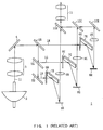
- Fig. 1 shows an example of the projector employing three mirror light valves respectively corresponding to the red, green, and blue components of the image data.
- white light consisting of substantially parallel light emitted from a high luminance white light source 2 (referred to as protection light hereinafter) L1 passes through an ultra violet (UV) cut filter (not shown) to get rid of unnecessary ultra violet therefrom and through a condenser lens 3 to be converted into parallel light having a narrower beam diameter so as to be incident to decomposing dichroic mirrors 5R, 5G, and 5B by a first reflecting mirror 4.
- UV ultra violet
- the decomposing dichroic mirrors 5R, 5G, and 5B decompose in color the incident projection light L1 into red light LR, green light LG, and blue light LB.
- the red light LR, green light LG, and blue light LB pass through beam shaping cylindrical lenses 6R, 6G, and 6B to be subjected to beam shaping therein and are incident by way of second reflecting mirrors 7R, 7G, and 7B to the reflecting surfaces of mirror light valves 8R, 8G, and 8B in such a manner as to be homogeneous thereon in illumination distribution.
- Each of the mirror light valves 8R, 8G, and 8B comprises a plurality of minute mirror elements respectively arranged in accordance with the arrangement of image data pixels.
- Each minute mirror element is arranged to correspond to each memory cell of a frame memory which cell corresponds in arrangement to each pixel of the image data, and is separately varied in inclination in accordance with the state of its corresponding memory cell so as to selectively reflect light incident thereto as effective reflected light necessary for forming an image or ineffective reflected light.
- image data for one frame respectively based on red, green, and blue components are set in frame memories corresponding to the mirror light valves 8R, 8G, and 8B respectively, and a driving circuit (not shown) drives under control the minute mirror elements based on the image data to form effective red light, effective green light, and effective blue light as effective reflected light.
- the effective red light, effective green light, and effective blue light are focused by their corresponding relay lenses 9R, 9G, and 9B respectively, and are directed to composing dichroic mirrors 10R, 10G, and 10B to be composed into color image light, which is enlargedly projected onto a screen (not shown) provided outside the projector 1 apart therefrom by way of a projector lens 11 having a zoom lens structure.
- the projector 1 is capable of projecting a color image based on an image data.
- the projector 1 having such a structure had a problem of becoming complicated in the optical system thereof and consequently large as a whole, since the projector 1 comprised an optical system for decomposing the projection light L1 emitted from the high luminance white light source 2 into the red light LR, green light LG, and blue light LB and an optical system for composing the effective red light, effective green light, and effective blue light respectively formed by the mirror light valves 8R, 8G, and 8B into color image light.
- the projector 1 had a problem that it used many optical components to be increased in cost.
- the projector 1 had also a problem that it was troublesome to attach the optical components thereto or adjust the attached optical components since it used many optical components.
- a projector comprising a color decomposition/composition means for decomposing white light in color into red light, green light, and blue light, which are incident to a first, a second, and a third mirror deflection type light modulators respectively, and for composing together a first effective reflected light to third effective reflected light respectively obtained from the first, second, and third mirror deflection type light modulators.
- White light is decomposed by the color decomposition/composition means into red light, green light, and blue light which are incident to first, second, and third mirror deflection type light modulators respectively and the first effective reflected light to third effective reflected light respectively obtained from the first, second, and third mirror deflection type light modulators are composed together. Therefore, the color decomposition/composition can be performed by the color decomposition/composition means, eliminating the necessity of separately provided color decomposition and composition optical systems, so that the optical system can be constructed easily.
- a preferred form of implementation of the invention described hereinbelow provides a projector which is simple and can be miniaturized.
- FIGs. 2A and 2B 20 shows a projector according to a first embodiment of the present invention as a whole.
- Projection light L20 composed of substantially parallel light emitted from a high luminance white light source 21 equipped with a reflector successively passes through a UV cut filter 22 and an infrared radiation (IR) cut filter (not shown) to get rid of unnecessary ultraviolet rays and infrared rays (heat rays) and is condensed while it passes through a condenser lens 23 to be incident to decomposing dichroic mirrors 24A, 24B and a reflecting mirror 25.
- IR infrared radiation
- the decomposing dichroic mirrors 24A, 24B and the reflecting mirror 25 are combined with one another in zigzag, wherein one end of the decomposing dichroic mirror 24B is arranged to be at an angle of 60° relative to the decomposing dichroic mirror 24A while the other end of the decomposing dichroic mirror 24B is arranged to be at an angle of 75° relative to one end of the reflecting mirror 25. Further, the decomposing dichroic mirrors 24A, 24B and the reflecting mirror 25 are positioned such that the optical axis of the projection light L20 goes through them at an angle of 20° from the upper.
- the projection light L20 of incident white light is subjected to color decomposition by reflecting, e.g., red light LR by the decomposing dichroic mirror 24A, e.g., green light LG by the decomposing dichroic mirror 24B and e.g., blue light LB by the reflecting mirror 25.
- the red light LR, green light LG, and blue light LB which are decomposed in color and reflected by the decomposing dichroic mirrors 24A, 24B and the reflecting mirror 25 are incident to the reflecting surfaces of mirror light valves 26R, 26G, and 26B which are arranged in such a manner that the red light LR, green light LG, and blue light LB have the same optical path length respectively.
- the condenser lens 23 is selected to condense the projection light L20 according to the reflecting surface sizes of the mirror light valves 26R, 26G, and 26B so that the red light LR, green light LG, and blue light LB are incident to the reflecting surfaces of their corresponding mirror light valves 26R, 26G, and 26B with uniform illumination.
- each of the mirror light valves 26R, 26G, and 26B a plurality of minute mirror elements each, for example, about 16 ⁇ m square corresponding to the pixel array (e.g., 768 ⁇ 576) of an image data are arranged to form a reflecting surface.
- the minute mirror elements are arranged corresponding to the memory cells of a frame memory which corresponds to the pixel array of the image data and the inclining state of each minute mirror element is separately varied in accordance with the state of its corresponding memory cell.
- each minute mirror element is designed to be inclined by +10° when the memory cell is ON relative to a neutral state, i.e., effective as a pixel as shown in Fig. 3A, and on the contrary inclined by -10° when the memory cell is OFF, i.e., ineffective as a pixel as shown in Fig. 3B.
- the high luminance white light source 21 is disposed at an angle of 20° relative to the horizontal axis so that the red light LR, green light LG, and blue light LB are incident to the reflecting surfaces of the mirror light valves 26R, 26G, and 26B with an incident angle of 20° with regard to the optical axis thereof respectively.
- the mirror light valves 26R, 26G, and 26B are designed to reflect the incident light by the minute mirror elements in two directions having an angle of 40° therebetween, one being that of effective reflected light necessary for forming the image and the other being that of ineffective light unnecessary for forming the image. Adding this, the reflecting surfaces of the mirror light valves 26R, 26G, and 26B are arranged to be inclined by -45° relative to the horizontal axis so as to prevent interference between the effective reflected light and the ineffective reflected light.
- a frame of image data based on each of the red, green, and blue components is set in each frame memory corresponding to each of the mirror light valves 26R, 26G, and 26B so that the same respectively form effective reflected light, i.e., effective red light, effective green light, and effective blue light based on the image data.
- the effective red light, effective green light, and effective blue light are reflected in a horizontal direction by minute mirror elements on the reflecting surfaces of the mirror light valves 26R, 26G, and 26B respectively to be incident to the decomposing dichroic mirrors 24A, 24B and the reflecting mirror 25 similarly to the color decomposition.
- the effective red light, effective green light, and effective blue light are reflected in a horizontal direction to avoid the optical paths of the red light LR, green light LG, and blue light LB so as to prevent interference between the former and the latter.
- the decomposing dichroic mirrors 24A, 24B and the reflecting mirror 25 reflect the incident effective red light, effective green light, and effective blue light in a horizontal and same direction to compose the same into color image light, which is incident to a relay lens 27.
- the incident color image light is condensed by the relay lens 27 to be focused at a given position and is incident to a reflecting mirror 28.
- the incident color image light is reflected by the reflecting mirror 28 in a given direction to be incident to a light receiving surface of a projector lens 29 having a zoom lens structure.
- the mirror light valves 26R, 26G, and 26B are respectively fixed to color adjusting mechanisms 30R, 30G, and 30B, which can adjust the positions, angles, etc,, of the reflecting surfaces so as to prevent the composed color image light from being blurred in color and the like.
- the relay lens 27 is designed to respectively have such a magnification as to condense the color image light so that the same becomes smaller in diameter than the aperture of the projector lens 29 to enter the projector lens 29 with certainty.
- the reflecting mirror 28 is inclined by 45° relative to the optical axis of the color image light to correct the -45° inclination of the color image light on the reflecting surfaces of the mirror light valves 26R, 26G, and 26B.
- the color image light is enlargedly projected onto a screen (not shown) provided outside the projector 20 apart therefrom after passing through the projector lens 29.
- the projector 20 is thus designed to be able to project a color image based on an image data.
- the projector 20 decomposes the projection light L20 emitted from the high luminance white light source 21 into the red light LR, green light LG, and blue light LB by the decomposing dichroic mirrors 24A, 24B and the reflecting mirror 25 which are arranged in zigzag, forms the effective red light, effective green light, and effective blue light based on the image data by allowing the decomposed red light LR, green light LG, and blue light LB to be incident to their corresponding mirror light valves 26R, 26G,.and 26B and reflects these effective red light, effective green light, and effective blue light by the decomposing dichroic mirrors 24A, 24B and the reflecting mirror 25 to compose them into color image light.
- the projector 20 can constitute the color decomposition optical system and the color composition optical system as an optical system using the decomposing dichroic mirrors 24A, 24B and the reflecting mirror 25 which are arranged in zigzag, so that it is possible to construct a smaller and simpler optical system compared with a conventional one.
- the number of optical components can be reduced in the projector 20, so that it is possible to construct the optical system at low cost and miniaturize the projector 20 as a whole.
- the projector 20 has few optical components, so that it is possible to assemble the optical components with ease and further adjust the assembled optical components with ease.
- the projector 20 comprises the relay lens 27 and the reflecting mirror 28 between the decomposing dichroic mirrors 24A and 24B and reflecting mirror 25 and the projector lens 29. Therefore, the color image light can be condensed to focus on a given position and can be reflected in a desired direction, so that it is possible to increase the degree of freedom in designing the optical system.
- the projector 20 decomposes the projection light L20 emitted from the high luminance white light source 21 into the red light LR, green light LG, and blue light LB by the decomposing dichroic mirrors 24A, 24B and the reflecting mirror 25 which are arranged in zigzag, forms effective reflected light, i.e., the effective red light, effective green light, and effective blue light based on the image data by allowing the decomposed red light LR, green light LG, and blue light LB to be incident to their corresponding mirror light valves 26R, 26G, and 26B and reflects these effective red light, effective green light, and effective blue light by the decomposing dichroic mirrors 24A, 24B and the reflecting mirror 25 in a same direction to compose them into color image light, so that color decomposition/composition can be performed by the decomposing dichroic mirrors 24A, 24B and the reflecting mirror 25 eliminating the necessity of separately provided color decomposition and composition optical systems, and consequently it is possible to construct the optical
- Figs. 4A and 4B in which components corresponding to those in Figs. 2A and 2B are denoted at same numerals show a projector 40 according to a second embodiment of the present invention, the projector 40 being constructed using a cross dichroic mirror 41 formed of two dichroic mirrors 41A and 41B which cross each other at right angles instead of the decomposing dichroic mirrors 24A, 24B and the reflecting mirror 25 which constitute the color decomposition/composition optical system in Figs. 2A and 2B.
- the projection light L20 of substantially parallel light emitted from the high luminance white light source 21 successively passes through the UV cut filter 22 and an IR cut filter (not shown) in a direction having an angle of 20° relative to the horizontal axis to get rid of unnecessary ultraviolet rays and infrared rays (heat rays) and is condensed while it passes through the condenser lens 23 to be incident to the cross dichroic mirror 41.
- the cross dichroic mirror 41 reflects, for example, the red light LR of the incident projection light L20 at an angle of 90° by one dichroic mirror 41A, and for example, the green light LG thereof by the other dichroic mirror 41B at an angle of -90° and allows, for example, the blue light LB thereof to pass through the cross dichroic mirror 41 for color decomposition.
- the red light LR, green light LG, and blue light LB are respectively incident to the reflecting surfaces of the mirror light valves 26R, 26G, and 26B at an angle of 20° which valves are arranged such that the red light LR, green light LG, and blue light LB have the same optical path length.
- the mirror light valves 26R, 26G, and 26B form effective reflected light, i.e., effective red light, effective green light, and effective blue light from the incident red light LR, green light LG, and blue light LB respectively.
- the effective red light, effective green light, and effective blue light are reflected in a horizontal direction by the reflecting surfaces of the mirror light valves 26R, 26G, and 26B respectively to be incident to the cross dichroic mirror 41. Accordingly, the effective red light, effective green light, and effective blue light can avoid the optical paths of the red light LR, green light LG, and blue light LB to prevent interference between the former and the latter.
- the cross dichroic mirror 41 reflects the incident effective red light and effective green light in a same direction at angles of 90° and -90° by the dichroic mirrors 41A and 41B respectively and allows the effective blue light to pass through the cross dichroic mirror 41 to compose them into color image light, which is incident to the relay lens 27.
- the effective red light and effective green light are reflected by the cross dichroic mirror 41, they are inverted relative to the effective blue light which has passed the cross dichroic mirror 41 with respect to their image, so that, for example, the minute mirror elements of the mirror light valves 26R and 26G for forming the effective red light and effective green light are designed to be driven under control so as to form the effective red light and effective green light based on a previously inverted image.
- the relay lens 27 condenses the incident color image light to have a beam diameter which can enter the projector lens 29, and the light enters the projector lens 29.
- the reflecting surfaces of the mirror light valves 26R, 26G, and 26B are inclined at an angle of -45° relative to the horizontal axis similarly to the first embodiment set forth above, the image based on the color image light which has passed through the projector lens 29 is in a state inclined at -45° .
- the whole optical system of the projector 40 is previously inclined at 45° to correct the inclination of the image.
- the color image light which has passed through the projector lens 29 is designed to be enlargedly projected onto a screen (not shown) disposed outside the projector 1 apart therefrom as a color image.
- the projector 40 decomposes the projection light L20 emitted from the high luminance white light source 21 into the red light LR, green light LG, and blue light LB by the cross dichroic mirror 41, forms the effective red light, effective green light, and effective blue light by allowing the decomposed red light LR, green light LG, and blue light LB to enter their corresponding mirror light valves 26R, 26G, and 26B respectively, and reflects the effective red light, effective green light, and effective blue light by the cross dichroic mirror 41 to compose them into the color image light.
- the color decomposition optical system and the color composition optical system can be incorporated into an optical component in the projector 40 by the cross dichroic mirror 41, so that it is possible to construct the optical system more easily compared with that described in the first embodiment.
- the projection light L20 emitted from the high luminance white light source 21 is decomposed by the cross dichroic mirror 41 into the red light LR, green light LG, and blue light LB, which are incident to their corresponding mirror light valves 26R, 26G, and 26B to be converted into effective reflected light, forming effective red light and effective green light based on an image inverted relative to that based on the effective blue light and the effective blue light, and the effective red light, effective green light, and effective blue light are composed into color image light by the cross dichroic mirror 41. Therefore, it is possible to construct the optical system more easily, thus realizing a projector which is simple and can be miniaturized.
- the second embodiment discussed above has dealt with a case where the minute mirror elements of the mirror light valves 26R and 26G which formed the effective red light and effective green light were driven under control to form the effective red light and effective green light which had been previously inverted, since the effective red light, effective green light, and effective blue light formed by the mirror light valves 26R, 26G, and 26B respectively were incident to the cross dichroic mirror 41 so that an image based on the effective red light and effective green light was inverted relative to that based on the effective blue light.
- the present invention is not limited thereto, but the effective red light and effective green light can be reflected by a reflecting mirror in advance and then incident to the cross dichroic mirror 41 to correct the inversion of the effective red light and effective green light.
- a projector 50 decomposes in color the projection light L20 emitted from the high luminance white light source 21 by allowing the projection light L20 to be incident to the cross dichroic mirror 41, reflects the red light LR by a dichroic mirror 41A thereof and the green light LG by the other dichroic mirror 41B thereof and allowing the blue light LB to pass through the cross dichroic mirror 41.
- the red light LR of these red light LR, green light LG, and blue light LB is incident to the mirror light valve 26R by a reflecting mirror 51, the green light LG is incident to the mirror light valve 26G by a reflecting mirror 52, and the blue light LB is incident to the mirror light valve 26B as it is. Accordingly, the mirror light valves 26R, 26G, and 26B form the effective red light, effective green light, and effective blue light based on their corresponding image data, and allow the effective red light and effective green light to be incident to the cross dichroic mirror 41 via the reflecting mirrors 51 and 52.
- the cross dichroic mirror 41 reflects the effective red light and effective green light in a same direction and allows the effective blue light to pass therethrough so as to compose these effective red light, effective green light, and effective blue light into color image light.
- the projector 50 is designed to prevent the inversion of the image based on the effective red light and effective green light by reflecting the effective red light and effective green light twice by the reflecting mirrors 51 and 52 and the dichroic mirrors 41A and 41B respectively.
- the first and second embodiments discussed above have dealt with a case in which the projection light L20 emitted from the high luminance white light source 21 is condensed as it passes through a condenser lens 23.
- the present invention is not limited thereto, but the projection light L20 can be formed into parallel light having a given beam diameter, for example, using two condenser lenses.
- first and second embodiments discussed above have dealt with a case in which white light was decomposed into red light, green light, and blue light, which were incident to the first, second, and third mirror deflection type light modulators and the decomposing dichroic mirrors 24A, 24B and the reflecting mirror 25 and the cross dichroic mirror 41 were provided as a color decomposition/composition means for composing together the first effective reflected light to third effective reflected light obtained from the first, second, and third mirror deflection type light modulators.
- the present invention is not limited thereto, but other various color decomposition/composition means can be employed so long as it can decompose white light into red light, green light, and blue light, which are incident to the first, second, and third mirror deflection type light modulators and compose together the first effective reflected light to third effective reflected light obtained from the first, second, and third mirror deflection type light modulators.
- the first and second embodiments discussed above have dealt with a case wherein the present invention was applied to the projectors 20 and 40.
- the present invention is not limited thereto, but is also applicable to TVs and the like.
- white light is decomposed by a color decomposition/composition means into red light, green light, and blue light, which are incident to first, second, and third mirror deflection type light modulators and first effective reflected light to third effective reflected light obtained by the first, second, and third mirror deflection type light modulators are composed together, so that color decomposition/composition can be performed by the color decomposition/composition means eliminating the necessity of separately provided color decomposition and composition optical systems, and consequently it is possible to construct an optical system with ease, thereby realizing a projector which is simple and can be miniaturized.
Landscapes
- Engineering & Computer Science (AREA)
- Multimedia (AREA)
- Signal Processing (AREA)
- Physics & Mathematics (AREA)
- General Physics & Mathematics (AREA)
- Projection Apparatus (AREA)
- Liquid Crystal (AREA)
- Video Image Reproduction Devices For Color Tv Systems (AREA)
Applications Claiming Priority (3)
| Application Number | Priority Date | Filing Date | Title |
|---|---|---|---|
| JP7290301A JPH09114022A (ja) | 1995-10-12 | 1995-10-12 | プロジエクタ装置 |
| JP290301/95 | 1995-10-12 | ||
| JP29030195 | 1995-10-12 |
Publications (2)
| Publication Number | Publication Date |
|---|---|
| EP0768800A1 true EP0768800A1 (de) | 1997-04-16 |
| EP0768800B1 EP0768800B1 (de) | 2002-07-03 |
Family
ID=17754356
Family Applications (1)
| Application Number | Title | Priority Date | Filing Date |
|---|---|---|---|
| EP96307346A Expired - Lifetime EP0768800B1 (de) | 1995-10-12 | 1996-10-09 | Farbprojektor |
Country Status (6)
| Country | Link |
|---|---|
| US (1) | US5895109A (de) |
| EP (1) | EP0768800B1 (de) |
| JP (1) | JPH09114022A (de) |
| KR (1) | KR100454616B1 (de) |
| DE (1) | DE69622119T2 (de) |
| ES (1) | ES2175039T3 (de) |
Families Citing this family (9)
| Publication number | Priority date | Publication date | Assignee | Title |
|---|---|---|---|---|
| DE69535346T2 (de) * | 1994-08-04 | 2007-05-24 | Texas Instruments Inc., Dallas | Anzeigevorrichtung |
| US6406148B1 (en) * | 1998-12-31 | 2002-06-18 | Texas Instruments Incorporated | Electronic color switching in field sequential video displays |
| TW460723B (en) * | 1999-10-14 | 2001-10-21 | Ind Tech Res Inst | Time sequential color projection display system |
| US20030218590A1 (en) * | 2002-05-23 | 2003-11-27 | Kiser David K. | Optics engine having multi-array spatial light modulating device and method of operation |
| US6947020B2 (en) | 2002-05-23 | 2005-09-20 | Oregonlabs, Llc | Multi-array spatial light modulating devices and methods of fabrication |
| US20040109138A1 (en) * | 2002-12-10 | 2004-06-10 | Kiser David K. | Apparatus for generating a number of color light components |
| US20040109139A1 (en) * | 2002-12-10 | 2004-06-10 | Kiser David K. | Apparatus for combining a number of images into a single image |
| US20040108973A1 (en) * | 2002-12-10 | 2004-06-10 | Kiser David K. | Apparatus for generating a number of color light components |
| US20040109140A1 (en) * | 2002-12-10 | 2004-06-10 | Kiser David K. | Apparatus for combining a number of images into a single image |
Citations (9)
| Publication number | Priority date | Publication date | Assignee | Title |
|---|---|---|---|---|
| EP0395156A1 (de) * | 1989-04-28 | 1990-10-31 | Koninklijke Philips Electronics N.V. | Optisches Anstrahlungssystem und Projektionsapparat mit einem derartigen System |
| EP0434041A1 (de) * | 1989-12-20 | 1991-06-26 | Canon Kabushiki Kaisha | Polarisierendes Beleuchtungsgerät |
| EP0443586A2 (de) * | 1990-02-22 | 1991-08-28 | Canon Kabushiki Kaisha | Projektor |
| EP0485268A1 (de) * | 1990-11-09 | 1992-05-13 | Thomson-Csf | Matrix-Bildprojektor mit zwei polarisierten Strahlen |
| EP0492636A1 (de) * | 1990-12-27 | 1992-07-01 | Canon Kabushiki Kaisha | Polarisierte Beleuchtungsvorrichtung und Projektor |
| EP0523988A1 (de) * | 1991-07-17 | 1993-01-20 | Victor Company Of Japan, Limited | Bildprojektor |
| EP0547601A2 (de) * | 1991-12-17 | 1993-06-23 | Texas Instruments Incorporated | Farbanzeigevorrichtung unter Verwendung räumlichen Modulatoren |
| WO1993018620A2 (en) * | 1992-03-05 | 1993-09-16 | Rank Brimar Limited | Spatial light modulator system |
| US5379135A (en) * | 1992-03-24 | 1995-01-03 | Victor Company Of Japan, Ltd. | Optical system for display apparatus |
Family Cites Families (8)
| Publication number | Priority date | Publication date | Assignee | Title |
|---|---|---|---|---|
| KR920005040B1 (ko) * | 1989-10-05 | 1992-06-25 | 주식회사 금성사 | Lcd 프로젝터 |
| US5467154A (en) * | 1992-02-20 | 1995-11-14 | Kopin Corporation | Projection monitor |
| US5420655A (en) * | 1992-12-16 | 1995-05-30 | North American Philips Corporation | Color projection system employing reflective display devices and prism illuminators |
| JP3318904B2 (ja) * | 1993-07-14 | 2002-08-26 | テキサス インスツルメンツ インコーポレイテツド | プロジエクタ装置 |
| ES2146674T3 (es) * | 1994-03-09 | 2000-08-16 | Daewoo Electronics Co Ltd | Sistema optico de proyeccion. |
| KR100236107B1 (ko) * | 1994-03-09 | 1999-12-15 | 전주범 | 투사형 화상표시장치(projection display system) |
| KR0130606B1 (ko) * | 1994-07-30 | 1998-04-11 | 배순훈 | 입체형 프로젝터(Projector) |
| US5612753A (en) * | 1995-01-27 | 1997-03-18 | Texas Instruments Incorporated | Full-color projection display system using two light modulators |
-
1995
- 1995-10-12 JP JP7290301A patent/JPH09114022A/ja active Pending
-
1996
- 1996-10-09 ES ES96307346T patent/ES2175039T3/es not_active Expired - Lifetime
- 1996-10-09 EP EP96307346A patent/EP0768800B1/de not_active Expired - Lifetime
- 1996-10-09 DE DE69622119T patent/DE69622119T2/de not_active Expired - Lifetime
- 1996-10-10 US US08/728,897 patent/US5895109A/en not_active Expired - Fee Related
- 1996-10-11 KR KR1019960045188A patent/KR100454616B1/ko not_active Expired - Fee Related
Patent Citations (9)
| Publication number | Priority date | Publication date | Assignee | Title |
|---|---|---|---|---|
| EP0395156A1 (de) * | 1989-04-28 | 1990-10-31 | Koninklijke Philips Electronics N.V. | Optisches Anstrahlungssystem und Projektionsapparat mit einem derartigen System |
| EP0434041A1 (de) * | 1989-12-20 | 1991-06-26 | Canon Kabushiki Kaisha | Polarisierendes Beleuchtungsgerät |
| EP0443586A2 (de) * | 1990-02-22 | 1991-08-28 | Canon Kabushiki Kaisha | Projektor |
| EP0485268A1 (de) * | 1990-11-09 | 1992-05-13 | Thomson-Csf | Matrix-Bildprojektor mit zwei polarisierten Strahlen |
| EP0492636A1 (de) * | 1990-12-27 | 1992-07-01 | Canon Kabushiki Kaisha | Polarisierte Beleuchtungsvorrichtung und Projektor |
| EP0523988A1 (de) * | 1991-07-17 | 1993-01-20 | Victor Company Of Japan, Limited | Bildprojektor |
| EP0547601A2 (de) * | 1991-12-17 | 1993-06-23 | Texas Instruments Incorporated | Farbanzeigevorrichtung unter Verwendung räumlichen Modulatoren |
| WO1993018620A2 (en) * | 1992-03-05 | 1993-09-16 | Rank Brimar Limited | Spatial light modulator system |
| US5379135A (en) * | 1992-03-24 | 1995-01-03 | Victor Company Of Japan, Ltd. | Optical system for display apparatus |
Also Published As
| Publication number | Publication date |
|---|---|
| KR100454616B1 (ko) | 2005-02-02 |
| JPH09114022A (ja) | 1997-05-02 |
| DE69622119D1 (de) | 2002-08-08 |
| DE69622119T2 (de) | 2003-02-27 |
| KR970022486A (ko) | 1997-05-28 |
| ES2175039T3 (es) | 2002-11-16 |
| EP0768800B1 (de) | 2002-07-03 |
| US5895109A (en) | 1999-04-20 |
Similar Documents
| Publication | Publication Date | Title |
|---|---|---|
| KR100382953B1 (ko) | 화상표시장치 | |
| EP1411379B1 (de) | Modulierbare Lichtquelle mit einer Anordnung aus einem VCSEL und einem elektromechanischen Gitter | |
| US7118225B2 (en) | Illumination system | |
| US5640479A (en) | Fiberoptic face plate stop for digital micromirror device projection system | |
| EP0704737B1 (de) | Optisches System für Drucker und Anzeigesysteme | |
| JPWO1998029773A1 (ja) | 画像表示装置 | |
| JP3195238B2 (ja) | 投影型カラー液晶表示装置 | |
| JP2002350974A (ja) | 投影型画像表示装置 | |
| US5706062A (en) | Projector system including keystone correction | |
| EP0768800B1 (de) | Farbprojektor | |
| US6799852B2 (en) | Image display projector | |
| GB2379281A (en) | Projection apparatus with reflecting device | |
| US6650460B2 (en) | Projection type display apparatus | |
| KR960016286B1 (ko) | 투사형화상표시장치 | |
| US5463434A (en) | Video projector with a plurality of projection devices | |
| JP2001091894A (ja) | 表示光学装置 | |
| CN101517456A (zh) | 投影显示器 | |
| EP1800473B1 (de) | Videoprojektor-beleuchtungssystem mit mehreren verbesserten dmd-bauelementen | |
| US7090353B1 (en) | System and method for improved digital projection | |
| JP3328238B2 (ja) | 単板反射型素子を用いた高輝度プロジェクタ | |
| JP3089171B2 (ja) | カラー液晶表示装置 | |
| JPH08313864A (ja) | プロジエクタ装置 | |
| JPH0353236A (ja) | リア型ビデオプロジェクター | |
| KR0173709B1 (ko) | 프로젝터의 컬러분리장치 | |
| KR100199874B1 (ko) | 투사형 화상표시장치의 광학계 |
Legal Events
| Date | Code | Title | Description |
|---|---|---|---|
| PUAI | Public reference made under article 153(3) epc to a published international application that has entered the european phase |
Free format text: ORIGINAL CODE: 0009012 |
|
| AK | Designated contracting states |
Kind code of ref document: A1 Designated state(s): DE ES GB |
|
| 17P | Request for examination filed |
Effective date: 19970904 |
|
| 17Q | First examination report despatched |
Effective date: 19990510 |
|
| GRAG | Despatch of communication of intention to grant |
Free format text: ORIGINAL CODE: EPIDOS AGRA |
|
| GRAG | Despatch of communication of intention to grant |
Free format text: ORIGINAL CODE: EPIDOS AGRA |
|
| GRAH | Despatch of communication of intention to grant a patent |
Free format text: ORIGINAL CODE: EPIDOS IGRA |
|
| GRAH | Despatch of communication of intention to grant a patent |
Free format text: ORIGINAL CODE: EPIDOS IGRA |
|
| GRAA | (expected) grant |
Free format text: ORIGINAL CODE: 0009210 |
|
| AK | Designated contracting states |
Kind code of ref document: B1 Designated state(s): DE ES GB |
|
| REF | Corresponds to: |
Ref document number: 69622119 Country of ref document: DE Date of ref document: 20020808 |
|
| REG | Reference to a national code |
Ref country code: ES Ref legal event code: FG2A Ref document number: 2175039 Country of ref document: ES Kind code of ref document: T3 |
|
| PLBE | No opposition filed within time limit |
Free format text: ORIGINAL CODE: 0009261 |
|
| STAA | Information on the status of an ep patent application or granted ep patent |
Free format text: STATUS: NO OPPOSITION FILED WITHIN TIME LIMIT |
|
| 26N | No opposition filed |
Effective date: 20030404 |
|
| PGFP | Annual fee paid to national office [announced via postgrant information from national office to epo] |
Ref country code: ES Payment date: 20091117 Year of fee payment: 14 Ref country code: DE Payment date: 20091001 Year of fee payment: 14 |
|
| PGFP | Annual fee paid to national office [announced via postgrant information from national office to epo] |
Ref country code: GB Payment date: 20091007 Year of fee payment: 14 |
|
| GBPC | Gb: european patent ceased through non-payment of renewal fee |
Effective date: 20101009 |
|
| REG | Reference to a national code |
Ref country code: DE Ref legal event code: R119 Ref document number: 69622119 Country of ref document: DE Effective date: 20110502 |
|
| PG25 | Lapsed in a contracting state [announced via postgrant information from national office to epo] |
Ref country code: GB Free format text: LAPSE BECAUSE OF NON-PAYMENT OF DUE FEES Effective date: 20101009 |
|
| REG | Reference to a national code |
Ref country code: ES Ref legal event code: FD2A Effective date: 20111118 |
|
| PG25 | Lapsed in a contracting state [announced via postgrant information from national office to epo] |
Ref country code: ES Free format text: LAPSE BECAUSE OF NON-PAYMENT OF DUE FEES Effective date: 20101010 |
|
| PG25 | Lapsed in a contracting state [announced via postgrant information from national office to epo] |
Ref country code: DE Free format text: LAPSE BECAUSE OF NON-PAYMENT OF DUE FEES Effective date: 20110502 |